Table of Contents
Advertisement
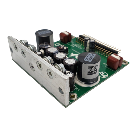
Dual Channel High Efficiency Power Amplifier Module
Description
The UcD102 amplifier module is a dual channel self-contained high-performance class D amplifier
intended for a wide range of audio applications, ranging from Public Address systems to ultrahigh-
fidelity replay systems for studio and home use. Chief distinguishing features are flat frequency
response irrespective of load impedance, nearly frequency-independent distortion behaviour and very
low radiated and conducted EMI. Control is based on a phase-shift controlled self-oscillating loop
taking feedback only at the speaker output.
Hypex Electronics BV
Kattegat 8
9723 JP Groningen, The Netherlands
+31 50 526 4993
sales@hypex.nl
www.hypex.nl
Highlights
Flat, fully load-independent frequency
response
Low output impedance
Very low, frequency-independent THD
Very low noise
Fully passive loop control
Consistent top performer in listening
trials
Features
Runs on unregulated +/- rails
Pop-free start and stop control
Differential audio input
DC-fault detection
Overcurrent protection
Weight: 55 g / Height: 24mm
Applications
Monitor loudspeakers for recording
and mastering studios
Audiophile power amplifiers for
professional and consumer use
Public Address systems
Home theatre systems
Active loudspeakers
Advertisement
Table of Contents

Related Manuals for Hypex Electronics UCD102


Summary of Contents for Hypex Electronics UCD102
- Page 1 Active loudspeakers Description The UcD102 amplifier module is a dual channel self-contained high-performance class D amplifier intended for a wide range of audio applications, ranging from Public Address systems to ultrahigh- fidelity replay systems for studio and home use. Chief distinguishing features are flat frequency response irrespective of load impedance, nearly frequency-independent distortion behaviour and very low radiated and conducted EMI.
-
Page 2: Table Of Contents
Contents Contents ................................2 Performance data ............................ 2 Audio Input Characteristics........................2 Absolute maximum ratings ........................3 Recommended Operating Conditions ....................3 Connections ............................. 4 Typical Performance Graphs ........................7 Mechanical Dimensions .......................... 9 Bridge-tied load (BTL) ........................... 10 1 Performance data Power supply = +/-35V, Load=4Ω, MBW=40kHz, Source imp=40Ω... -
Page 3: Absolute Maximum Ratings
3 Absolute maximum ratings Correct operation at these limits is not guaranteed. Operation beyond these limits may result in irreversible damage. Item Symbol Rating Unit Notes Power supply voltage +/-48 Shuts down when either rail exceeds 50V Peak output current Unit current-limits at 8A OUT,P Input voltage... -
Page 4: Connections
Note 1: Pin 3, 4, 5, 15, 16, 22, 32, 33 and 34 are physically connected to the same potential (ground). Note 2: Dissipation in the UcD102 can be lowered by using external driver voltage other than GND, see section 5.5 for additional info. - Page 5 5.1 DC-Error Detection Characteristics The UcD102 has an integrated DC-error detection which will pull pin 28 low in case of such an event. It is recommended to sense this fault condition and to interrupt both power supply lines in such an event.
- Page 6 5.3 Input buffer recommendation The UcD102 has no on-board input buffer. Applications that require a higher gain and/or a higher input impedance benefit from a buffer stage like shown below. Figure Recommended Input buffer stage. 5.4 Amplifier start-up delay During initial power up the amplifier is disabled for approx. 1.5s regardless of the state of pin 27. Once powered up there is no start or stop delay.
-
Page 7: Typical Performance Graphs
6 Typical Performance Graphs The graphs were taken on one stock UcD102 module powered by an SMPS400A100. Refer to the tables in section 1 for guaranteed limits. 6.1 THD+N over power and frequency 0.05 0.05 0.02 0.02 0.01 0.01 0.005 0.005... - Page 8 6.2 Frequency Response (4Ω, 8Ω and open circuit) 6.3 Output Impedance 6.4 18,5+19,5kHz IMD (10W, 8Ω)
-
Page 9: Mechanical Dimensions
7 Mechanical Dimensions... -
Page 10: Bridge-Tied Load (Btl)
In the graphical representation above, the BTL principle is depicted. By inverting the signal input of the second channel, the output voltage amplitude is doubled. Please note that the negative (GND) output terminals are tied together. On the UcD102 module, this is already implemented in the design and therefor these pins can be left unconnected. - Page 11 LIFE SUPPORT POLICY: Use of Hypex products in life support equipment or equipment whose failure can reasonably be expected to result in injury or death is not permitted except by explicit written consent from Hypex Electronics BV. Document Description...
- Page 13 ELECTRICAL PARTS LIST...
- Page 14 100Ω,0603,1/10W,±1%,RC0603FR- 07100RL Ω,0603,1/10W,±1% 180Ω,0603,1/10W,±1%,RC0603FR- R8, R37, R55, R84 07-91800-00 Chip Resistor 07180RL 200Ω,0603,1/10W,±1%,RC0603FR- R14, R29, R33, R61 07-92000-00 Chip Resistor 07200RL R18, R27, R36, R41, R76, R94, 220Ω,0603,1/10W,±1%,RC0603FR- 07-92200-00 Chip Resistor R125, R143 07220RL 270Ω,0603,1/10W,±1%,RC0603FR- R53, R57, R133, R134 07-92700-00 Chip Resistor 07270RL 470Ω,0603,1/10W,±1%,RC0603FR-...
- Page 15 1uK,16V,0603,X7R,C1608X7R1C105 220nK,25V,0603,X7R,C1608X7R1E2 24KT C9, C12, C34, C37 26-22251-10 Ceramic Chip Capacitor 2n2J,50V,0603,NPO C6, C16, C31, C41 26-39151-00 Ceramic Chip Capacitor 390PJ,50V,0603,NPO C11, C18, C19, C20, C36, C43, C44, 470nK,25V,0603,X7R,C1608X5R1E4 26-47421-20 Ceramic Chip Capacitor C45, C51 74KT C3, C23, C28, C48 26-47151-00 Ceramic Chip Capacitor 470pJ,50V,0603,NPO...
Need help?
Do you have a question about the UCD102 and is the answer not in the manual?
Questions and answers