
Related Manuals for Mindray Datascope Duo


Summary of Contents for Mindray Datascope Duo
- Page 1 S e r v i ce M a n u a l 0070-01-0604-02_revB_Duo srv color.indd 1 3/10/10 5:17:19 PM...
- Page 2 S e r v i ce M a n u a l...
- Page 3 CleanShield are U.S. registered trademarks of Masimo Corp. © Copyright Mindray DS USA, Inc., 2008. All rights reserved. Contents of this publication may not be reproduced in any form without permission of Mindray DS USA, Inc. 0070-10-0604-01 Duo Service Manual...
-
Page 4: Table Of Contents
Table of Contents Foreword ............................... iii Warnings, Precautions And Notes ........................iii Theory of Operation ......................1 - 1 Introduction ..............................1 - 1 Hardware Overview ............................1 - 2 Power Supply Board ..........................1 - 2 Fan Driver Board Overview ........................1 - 4 CPU/Display Board Overview ........................ - Page 5 Table of Contents This page intentionally left blank. 0070-10-0604-01 Duo™ Service Manual...
-
Page 6: Foreword
Foreword Introduction Foreword This service manual gives a detailed description of the Duo Portable Patient Monitor, including circuit descriptions, test and calibration procedures, and spare parts listings. This manual is intended as a guide for technically qualified personnel during repair, testing, or calibration procedures. - Page 7 Introduction Warnings, Precautions And Notes This page intentionally left blank. 0070-10-0604-01 Duo™ Service Manual...
-
Page 8: Theory Of Operation
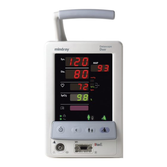
Theory of Operation Introduction The Duo is a compact, lightweight, portable patient monitor intended for monitoring the following vital signs: blood pressure, SpO (optional), and pulse rate on adult and pediatric patients. The Duo monitor can be powered by either the internal rechargeable Lithium-Ion battery or external 100~240 volt 50/60 Hz AC. -
Page 9: Hardware Overview
Hardware Overview Theory of Operation Hardware Overview Patient Connectors Module Driver NIBP Module Isolated SpO Power Supply* AC Input Power Supply Keypad Switches CPU / Display pcb External RS232 - TTL Serial Lithium-Ion Interface Inverter** Interface** Battery FIGURE 1-1 Interconnection Block diagram The Isolated SpO Power Supply is present with optional Masimo and Nellcor SpO ONLY. - Page 10 Theory of Operation Hardware Overview FIGURE 1-2 Power Supply Block Diagram Power Supply Voltage Test Points: Location Function Measure across C5 Primary Rectified Voltage (DC). Range: 105 - 374 volts. C5 Negative Lead Primary Ground. Measure across Q1 pin1 and 110k Hz Drive frequency.
-
Page 11: Fan Driver Board Overview
Hardware Overview Theory of Operation 1.2.2 Fan Driver Board Overview The Fan Drive Board is active during the battery charging cycle. The Temperature Detector senses the temperature of the heat sink of the Secondary Rectifier diode and turns on the fan when the heat sink reaches a certain temperature. -
Page 12: Nibp Module Overview
Theory of Operation Hardware Overview A/D Converter RTC/ E PROM Keypad SpO2 NIBP Module Module FPGA User Interface External Serial Interface Interface LED Array Indicator Display LEDs FIGURE 1-4 CPU/Display Board Block Diagram CPU Board Test Points Location Function VPP in +12 vdc power supply VDD in +3.3 vdc power supply... -
Page 13: Spo Overview
Hardware Overview Theory of Operation 1.2.5 Overview Pulse oximetry (SpO ) measurement is used to determine the oxygen saturation level of the patient's blood. The SpO numeric display indicates the amount of hemoglobin that has bonded with oxygen molecules to form oxyhemoglobin. By analyzing the pulse in the fingertip using specified algorithm and consulting the clinical data table, we can obtain the value. -
Page 14: Calibration And Performance Verification
Calibration and Performance Verification Introduction The following procedures are provided to verify the proper operation of the Duo monitor. A menu driven interface is used to execute all verification tests. Performance tests should be performed at least once per year and after any preventive maintenance or repair has been performed. -
Page 15: Warnings And Guidelines
Warnings and Guidelines Calibration and Performance Verification Warnings and Guidelines In the event that the instrument cover is removed, observe the following warnings and guidelines: 1. Do not short component leads together. 2. Perform all steps in the exact order they are given. 3. -
Page 16: Calibration And System Checks
Calibration and Performance Verification Calibration and System Checks Calibration and System Checks 2.4.1 Device Appearance and Installation Checks Inspect the Duo monitor to ensure that: • The outer housing is clean and has no scratches or cracks • When the device is gently shaken, there are no loose components •... -
Page 17: Software Version Mode
Calibration and System Checks Calibration and Performance Verification 2.4.4 Software Version Mode Use the following procedure to view the software version. 1. Ensure that the Duo is powered OFF. 2. Press and hold the Patient Size key. 3. While continuing to hold the Patient Size key, press and hold the Power ON/OFF key for two (2) seconds until the Duo beeps. -
Page 18: Safety Test
Calibration and Performance Verification Safety Test Safety Test 2.5.1 Test Equipment • Safety Analyzer (Dempsey model 431 or equivalent) 2.5.2 Case Leakage 1. Plug the line cord of the unit into the safety analyzer. 2. Connect the case ground lead of the analyzer to the equipotential lug of the Duo monitor. -
Page 19: Nibp Calibration
NIBP Calibration Calibration and Performance Verification NIBP Calibration 2.6.1 Test Equipment • NIBP simulator • NIBP test chamber/dummy cuff • Manometer with bulb 2.6.2 Test Procedure 2.6.2.1 Transducer Accuracy 1. Connect the 500 cc Test Chamber and calibrated manometer via a ‘‘T’’ fitting to the NIBP fitting on the Duo monitor under test. - Page 20 Calibration and Performance Verification NIBP Calibration NOTE: The actual measured values displayed on the Duo monitor may not compare with the selected target pressure on the simulator. This test is intended to confirm the REPEATABILITY, not accuracy, of dynamic NIBP readings. Accuracy can only be confirmed by performing the NIBP Calibration outlined in section 2.6 of this manual.
-
Page 21: Spo 2 Verification
Verification Calibration and Performance Verification Verification 2.7.1 Test Equipment • SpO simulator 2.7.2 Test Procedure 1. Connect the appropriate SpO probe connector to the Duo monitor. 2. Connect the SpO probe to the SpO simulator. 3. Set the simulator target values to: = 98% Pulse Rate = 70 4. -
Page 22: Parts
Parts Introduction This section contains exploded views of the Duo monitor, internal modules, and parts list. Duo Service Manual 0070-10-0604-01 3 - 1... - Page 23 Introduction Parts Module See SpO Detail FIGURE 3-1 Duo Exploded View 3 - 2 0070-10-0604-01 Duo Service Manual...
- Page 24 Parts Introduction FIGURE 3-2 Masimo SpO Detail Duo Service Manual 0070-10-0604-01 3 - 3...
- Page 25 Introduction Parts FIGURE 3-3 Nellcor SpO Detail 3 - 4 0070-10-0604-01 Duo Service Manual...
- Page 26 Parts Introduction Battery Latch Detail FIGURE 3-4 Main Frame Duo Service Manual 0070-10-0604-01 3 - 5...
- Page 27 Introduction Parts FIGURE 3-5 Rear Case Assembly 3 - 6 0070-10-0604-01 Duo Service Manual...
- Page 28 Parts Introduction FIGURE 3-6 Front Case Assembly Duo Service Manual 0070-10-0604-01 3 - 7...
- Page 29 Introduction Parts FIGURE 3-7 Battery Connector Assembly Detail 3 - 8 0070-10-0604-01 Duo Service Manual...
- Page 30 Parts Introduction Screws, mounting plate* Duo monitor Washers, locking* mounting plate* Mounting screw for basket* Utility basket Mounting screw for basket* Casters, locking Casters, Non locking Washers, locking* Mounting bolts, pole* FIGURE 3-8 Duo Rolling Stand Replacement Parts, Duo Rolling Stand DESCRIPTION PART NUMBER Duo rolling stand, value...
-
Page 31: Parts Listing
Parts Listing Parts Parts Listing REF. NUMBER PART NUMBER DESCRIPTION 0211-00-0146 Housing Screw (metric panhead) 0380-00-0475 Rear Housing 0441-00-0107 Chassis 0671-00-0045 Power Supply Board 0211-00-0145 Metric Panhead Screw 0671-00-0044 CPU/Display Board 0213-00-0032 Self Tapping Screw 0380-00-0472 Nellcor Connector Shroud 0380-00-0473 Masimo Connector Shroud 0380-00-0476 Front Housing... - Page 32 Parts Parts Listing REF. NUMBER PART NUMBER DESCRIPTION 0330-00-0052 Keypad Overlay 0103-00-0411 Pneumatic Fitting 0386-00-0309 Mounting Plate See table below Rear Label, Upper See table below Display Overlay See table below Connector Label N/S - Not Shown Display Overlay LANGUAGE OPTION PART NUMBER English...
- Page 33 Parts Listing Parts This page intentionally left blank. 3 - 12 0070-10-0604-01 Duo Service Manual...
-
Page 34: Repair Information
Repair Information Introduction This chapter of the Duo Service Manual provides the necessary technical information needed to perform repairs on the instrument. The most important prerequisites for effective troubleshooting are a thorough understanding of the instrument functions as well as an understanding of the theory of operation. -
Page 35: Troubleshooting Guide
Troubleshooting Guide Repair Information Troubleshooting Guide Error Codes and Solutions MESSAGE/ PROBLEM REASON SOLUTION NIBP Self Test Error NIBP Module hardware failure NIBP Communications Communications with NIBP Module have failed Error Loose Cuff Cuff is not properly wrapped or no cuff is present Air Leak Cuff, hose or connector is damaged, internal leak Air Pressure Failure... - Page 36 Repair Information Troubleshooting Guide Error Codes and Solutions (Continued) MESSAGE/ PROBLEM REASON SOLUTION Masimo SpO Pulse Pulse Rate value exceeds the measurement range Rate Exceeded Nellcor SpO Pulse Rate value exceeds the measurement range Exceeded Nellcor SpO Noise is detected on the pulse signal, preventing Interference pulse discrimination from the noise.
- Page 37 Troubleshooting Guide Repair Information Monitor Failures MESSAGE/ PROBLEM REASON SOLUTION No display after Bad line fuse Replace fuse power-on, power Bad power supply Replace power supply indicator does not Bad CPU/Display Replace CPU/Display board light. board NIBP or SpO will CPU/Display board or Isolate and replace defective board/module not function.
- Page 38 Repair Information Troubleshooting Guide Module Failures MESSAGE/ PROBLEM REASON SOLUTION NIBP cuff cannot Pinched or leaking hose Check hose and cuff. Replace as needed be inflated. or cuff Intermittently won't Loose cuff or patient Keep the patient quiet. Reapply cuff take an NIBP movement reading.
-
Page 39: Disassembly Instructions
Disassembly Instructions Repair Information Disassembly Instructions Before disassembling the unit, perform the following: • Turn off the unit and remove the line cord • Remove all cables and hoses • Remove the battery • Perform all maintenance on a properly grounded work station. 4.3.1 Tools Needed •... -
Page 40: Power Supply Removal
Repair Information Disassembly Instructions 4.3.7 Power Supply Removal 1. Remove the battery cable from P1 on the power supply PCB. 2. Remove four (4) 3 x 6 mm Phillips panhead machine screws from the corners of the power supply PCB. 3. - Page 41 0070-10-0604-01 Revision F July 12, 2010...
- Page 42 Tel: +31 33 25 44 911 • Fax: +31 33 25 37 621 Mindray (UK) Limited • 3 Percy Road • St. John’s Park • Huntingdon • Cambridgeshire PE29 6SZ • United Kingdom • Tel: 01480 416840 • Fax: 01480 436588 Mindray Medical France SARL •...
Need help?
Do you have a question about the Datascope Duo and is the answer not in the manual?
Questions and answers