
Subscribe to Our Youtube Channel
Related Manuals for Mindray DC-8


Summary of Contents for Mindray DC-8
- Page 1 DC-8/DC-8 PRO/DC-8 CV/DC-8 EXP/DC-8S Diagnostic Ultrasound System Service Manual Revision 19.0...
-
Page 3: Table Of Contents
Table of Content Table of Content........................i Revision History ........................I Intellectual Property Statement ..................III Applicable for........................III Statement ........................... III Responsibility on the Manufacturer Party ............... IV Customer Service Department ..................IV Safety Precautions....................1-1 Meaning of Signal Words ....................1-1 Symbols .......................... - Page 4 3.4.1 Connecting the Footswitch ..................3-8 3.4.2 Installing a Graph / Laser Printer ................3-9 3.4.3 Installing Video Printer ..................... 3-9 3.4.4 Installing Barcode Scanner ..................3-11 System Configuration ....................3-13 3.5.1 Running the System ....................3-13 3.5.2 Enter into DOPPLER ....................3-13 3.5.3 System Preset .......................
- Page 5 5.4.1 Checking Flow ......................5-5 5.4.2 Content ........................5-5 Performance Test ......................5-10 5.5.1 Test Process ......................5-10 5.5.2 Test Content......................5-10 Software Installation &Maintenance ................ 6-1 Enter into Maintenance ....................6-1 Software Installation/Restoration ..................6-2 Enter into Windows ......................6-2 Software maintenance .....................
- Page 6 9.3.11 Minor Panel Assembly .................... 9-26 9.3.12 Others ........................9-31 10 Optional Installation/Assembly ................10-1 10.1 Installing Optional Software ................... 10-1 10.2 Installing Optional Hardware ..................10-3 10.2.1 Front Board USB&ECG and Pencil Probe Port Assembly ........10-4 10.2.2 4D Module ......................10-12 10.2.3 Elastography ......................
- Page 7 12.3.4 Mechanical Safety Inspection ................. 12-9 12.3.5 Electrical Safety Inspection ................... 12-11 13 Troubleshooting of Regular Malfunctions............. 13-1 13.1 Troubleshooting When System Can’t Be Powered on ............ 13-1 13.1.1 Module or Board Related ..................13-1 13.1.2 Key Points Supporting Troubleshooting ..............13-1 13.1.3 Troubleshooting When System Can’t Be Powered on ..........
-
Page 9: Revision History
Revision History Mindray may revise this publication from time to time without written notice. Revision Date Reason for Change 2011.11.25 Initial release Modify the content of “12 Preventive Maintenance” and let it more practical. Increase detailed picture and description of “6.2.1.2 Operation System and Doppler restoration”. - Page 10 EXP which is no longer served as FRU. 6. Add digital board FRU used on non-EXP in Win7. 7. Add Hard disk used in OS Win7 for DC-8 non-EXP and EXP in the region of CE/FDA/India/Russia & CIS. 8. 10.1 Add picture of the screen for Promote function. Update screen picture for uninstalling the options.
-
Page 11: Intellectual Property Statement
Intellectual Property Statement SHENZHEN MINDRAY BIO-MEDICAL ELECTRONICS CO., LTD. (hereinafter called Mindray) owns the intellectual property rights to this Mindray product and this manual. This manual may referring to information protected by copyright or patents and does not convey any license under the patent rights or copyright of Mindray, or of others. -
Page 12: Customer Service Department
Mindray or repairs by people other than Mindray authorized personnel. -
Page 13: Safety Precautions
Safety Precautions This chapter describes important issues related to safety precautions, as well as the labels and icons on the ultrasound machine. Meaning of Signal Words In this operator’s manual, the signal words DANGER, WARNING, CAUTION and NOTE are used regarding safety and other important instructions. The signal words and their meanings are defined as follows. -
Page 14: Warning Labels
Caution. 1.2.2 Warning Labels Warning Labels Meaning a. Do not place the device on a sloped surface. Otherwise the device may slide, resulting in personal injury or the device malfunction. Two persons are required to move the device over a sloped surface. b. -
Page 15: Safety Precautions
Symbol Description Transducer sockets Network port Serial port Connects the control port of the video printer USB port Used for DVI-D signal output. Used for VGA output. Reserved, used for separate video input Reserved, used for separate video output Reserved, used for stereo audio input. Reserved, used for stereo audio output. -
Page 16: Electric Safety
Use the power cord accompanied with the system provided by Mindray. Disconnect the AC power before you clean or uninstall the ultrasound machine, otherwise, electric shock may result. -
Page 17: Personnel Safety
The user is not allowed to open the covers and panel of the system, neither NOTE: device disassemble is allowed. To ensure the system performance and safety, only Mindray engineers or engineers authorized by Mindray can perform maintenance. Only technical professionals from Mindray or engineers authorized by Mindray after training can perform maintenance. -
Page 19: Specifications
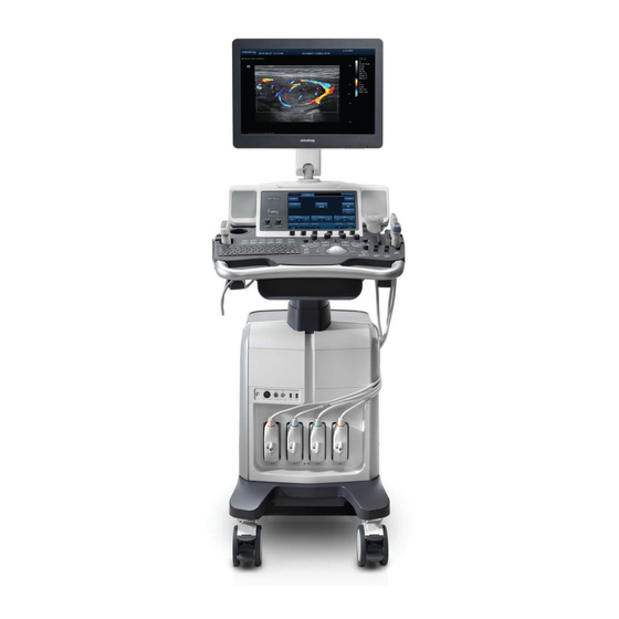
Specifications Overview 2.1.1 Intended Use The DC-8/DC-8 PRO/DC-8 CV/DC-8 EXP/DC-8S diagnostic ultrasound system is intended for use in clinical ultrasonic diagnosis. 2.1.2 Introduction of Each Unit Specifications 2-1... - Page 20 Name Function Monitor Displays the images and parameters during scanning. Touch screen panel Operator-system interface or control. Main control panel Operator-system interface or control. Storage compartment Used for placing small objects. Used for connecting the ECG leads, PCG transducer, footswitch, Physio panel external ECG device and PCG signal etc.
- Page 21 USB_MIC port USB port and MIC port. Endocavity probe Used for fixing the endocavity probe. holder DVD-RW DVD-RW drive. Ultrasound gel holder/ Used for placing the ultrasound gel or installing the gel heater. gel heater Pencil probe holder Reserved. Probe holder Used for placing general probe, endocavity probe or 4D volume probe.
- Page 22 USB ports Support USB2.0 Network port Support 10/100/1000Mbit Ethernet Audio signal input port, left Reserved channel. Audio signal input port, right Reserved channel. Audio signal output port, left channel. Audio signal output port, right channel. Used for separate video input Reserved, suppoty PAL and NTSC.
- Page 23 2.1.2.2 Power Supply panel Name Function Used for equipotential connection, that balances the protective Equipotential earth potentials between the system and other electrical terminal equipment. Power outlet Supply power for optional peripheral devices. Circuit breaker Used for switching off/ on the power supply. Power inlet AC power inlet.
- Page 24 2.1.2.4 Control Panel DC-8/DC-8 PRO/DC-8 CV/DC-8S 2-6 Specifications...
- Page 25 DC-8 EXP Specifications 2-7...
- Page 26 Exam Operation Control Symbol Name Function Type Functional End Exam End the current exam. button Patient Functional Enter/ exit Patient Info screen. Information button Probe/Exam Functional Switch probe and exam mode. switch button Functional Review Enter/ exit the Review screen. button Functional Report...
- Page 27 Image operations Control Symbol Name Function Type Pressable Press to enter B mode; Rotate to adjust B mode gain. knobs Press to enter M mode, and rotate to adjust M gain; Pressable while in 3D/4D mode, rotate the knob to make the 3D knobs image to rotates around X axis.
- Page 28 Enter TDI imaging. Enter contrast imaging. Undefined Undefined Button, set by the user in preset. Button Undefined Undefined Button, set by the user in preset. Button Functional Enter single window in multiple window mode. button Enter Dual mode in Non-Dual mode; Functional Switch between the two display windows in Dual button...
- Page 29 Parameter Adjustment Control Symbol Name Function Type Deflector Depth Adjust depth in real-time imaging. Pressable Rotate to enter the pan zoom mode, and press to enter Zoom knobs the spot zoom mode. Slide bar Adjust the depth gain. Functional Angle Adjust angle.
- Page 30 Measurement, Comment, and Body Mark Operations Control Symbol Name Function Type Functional Measurement Enter or exit the general measurement mode. button Functional Caliper Enter/ exit the application measurement mode. button Functional Comment Enter/ exit the textual comment status. button Functional Arrow Enter/ exit the arrow comment status.
-
Page 31: Peripherals Supported
2.1.3 Peripherals Supported Peripherals supported by this system please refer to the Operator’s Manual [Basic Volume] attached. Specifications 2.2.1 Dimensions & Weight Dimension: 1355~1800mm (H)×930mm (D)×585mm (W)Net weight: about 110Kg 2.2.2 Electrical Specifications 2.2.2.1 AC Input Voltage 220-240~,100-127V~ Frequency 50/60Hz Power consumption 800VA Specifications 2-13... -
Page 32: Environmental Conditions
2.2.2.2 Battery Voltage 11.1V Capacity 4800mAh 2.2.3 Environmental Conditions Operating conditions Storage and transportation conditions Ambient temperature 0℃~40℃ -20℃~55℃ Relative humidity 30%~85% (no condensation) 30%~95% (no condensation) Atmospheric pressure 700hPa~1060hPa 700hPa~1060hPa Do not use this system in the conditions other than those Warning :... -
Page 33: System Installation
System Installation Preparations for Installation Do not install the machine in the following locations: NOTE: Locations near heat generators; Locations of high humidity; Locations with flammable gases. 3.1.1 Electrical Requirements 3.1.1.1 Requirement of Regulated Power Supply Power specification is showing in 2.2.2.Due to the difference of the power supply stability of different districts, please advise the user to adopt a regulator of good quality and performance such as an on-line UPS. -
Page 34: Installation Conditions
Installation Conditions 3.1.2 3.1.2.1 Space Requirements Place the system with necessary peripherals in a position that is convenient for operation: 1. Place the system in a room with good ventilation or an air conditioner. 2. The door is at least 0.8m wide. The ultrasound machines can move into the room easily. 3. -
Page 35: Confirmation Before Installation
3.1.3 Confirmation before Installation Perform the following confirmation before installing the system: 1. The video format used in the region or country where the system is installed. 2. The language used in the region or country where the system is installed. 3. - Page 36 Take away the probe carrying case, accessories case and the protecting foams, then cut the bands rounding the machine, see the figure below: Take out the frontal baffle-board. Take the control panel handle to lift the machine slightly, remove the frontal baffle-board (two person ), see the figure below: 3-4 System Installation...
-
Page 37: Notice Of Packing
Unlock the casters, hold the hand holder and lift up the machine (make the posterior casters landing on the ground), and then push down the machine carefully. 3.2.2 Notice of Packing Please operate as follows when packing the machine again: As shown in the figure, dial the white fixing perch between two supporting arms, meanwhile, press the supporting arm down to the lowest position (about 45 degree from horizontal position) then do the related operation. -
Page 38: Checking
3.2.3 Checking After unpacking, check the objects in the container with the package list to see if anything is in short supply or is wrong. Inspect and make sure there is no damage to the machine, no indentation, no cracks. NOTE: When install the machine, the customer Service engineer should check rising and lowering of machine. -
Page 39: Connecting Ecg
2. Push the retaining clamp downward, and lock the power cord, as shown in the figure (b) above. 3. Plug the other end power plug into an appropriate outlet. The grounding terminal should be connected with a power grounding cable to ensure that protective grounding works normally. NOTE: Make sure to allow sufficient slack in the cable so that the plug is not pulled out of the wall if the system is moved slightly. -
Page 40: Connecting The Transducer
3.3.5 Connecting the Transducer Four sockets (A, B, C, D) are configured on the system; Every socket can be connected with all types of supported transducers. 1. Keep the cable end of the transducer to the right side of the system, and insert the connector into the socket of the system, and then press in fully. -
Page 41: Installing A Graph / Laser Printer
Function setting: for details, please refer to “3.5.3 System Preset”. 3.4.2 Installing a Graph / Laser Printer The graph / laser printer is connected to the system via the USB port on system. As shown in the figure below, a graph / laser printer has a power cord and a data cable. Connect the data cable with the USB port on the system. - Page 42 Take UP-897MD for example. 1. Plug the AC power cord hidden in the compartment under the control panel of the system to the AC LINE port of the printer. 2. Connect the video signal cable in the compartment to the VIDEO IN port on the printer, and connect the Remote control cable to the Remote port on the printer.
-
Page 43: Installing Barcode Scanner
Installing a color video printer 3.4.3.2 Digital Video Printer The installation method of B/W digital Video Printer is similar to color digital Video Printer. Take MITSUBISHI P93DC for example. 1. Place the printer inside the compartment. Place another printer, if available, on the platform behind the control panel. - Page 44 Connect the cable to the port on the scanner. Connect the other end of the cable to the USB port on the ultrasound system. When the ultrasound system is working, information scanning can be performed by pressing the switch on the scanner. For detailed operations, please refer to the operator’s manual of the scanner.
-
Page 45: System Configuration
System Configuration 3.5.1 Running the System Connect the AC power; make sure the ultrasound system and other optional devices are correctly connected. The circuit breaker should be in the [Up] position for the system to be operational. When the AC power indicator on the control panel is light on (indicator is in green), press the power button on the minor control panel to turn on the system. -
Page 46: Print Preset
Click [System Preset] to open the System Preset screen. The following settings can be performed on the System Preset screen. Item Region: preset the hospital name, date and time, and select the language. Key Config: preset the function of user defined keys (F3~F6, F12, P1, P2) and the footswitch, key lightness, key volume and trackball speed can be adjusted. - Page 47 The printer related information will be displayed automatically, if additional printer is needed, click [Add Printer] to do the setting. Click [Next] on the Add Printer Wizard screen to open the following screen. Add Local printer Select “Local printer attached to this computer”, then click [Next], the system will detect the printer connected with the ultrasound machine.
-
Page 48: Network Preset
In case of installation failure in Doppler, try to install the printer in Windows (click [Enter Windows] on the Maintenance menu). If the installation can’t be performed neither in Doppler nor Windows, then the printer can’t be supported by the ultrasound system. Use the original drive disk to perform the drive installation. -
Page 49: Dicom Preset
Click [IP Config] to enter the following dialog box: Select “DHCP”, and then click [Apply]. Or, select "Static", input the IP address, subnet mask and gateway, then click [Apply]. IP address of the system should be at the same network segment as that of the NOTE: server. - Page 50 clicking [Ping]. Click [Add] to add the server to the list if the connection works normally. The following is an example: NOTE: AE Title should be the same with the SCU AE Title preset in the server (PACS/RIS/HIS). DICOM communication port should be the same with the one in the server. If the currently entered name has already existed, the system will pop up: “The server name exists!”...
-
Page 51: Check System Information
The DICOM Service Setting is used to set properties of DICOM services as Storage, Print, Worklist, MPPS, Storage Commitment and Query/ Retrieve. The detailed information please refer to “DICOM” of user manual. NOTE: Only if DICOM basic option is configured, Worklist page is available. 3.5.7 Check System Information In System Information screen, it displays the product configuration, the optional installation status,... -
Page 53: Product Principle
Product Principle General Structure of Hardware System Symbols illustration ECG/PCG board and Display& Ultrasound Control touch DVD-R/W Gel Heater panel extending screen board DC power cable conne Signal port ction Digital IO BOX board Back -end mother board board 4D or 4D&TEE Back-end unit... -
Page 54: Ultrasound Front-End Unit
Power supply unit (front-end power board, back -end power board, AC/DC power board). Ultrasound Front-end Unit Signal processing board High Beamformer data Beamformer voltage FPGA 2 Communication isolation control bus PCIE Clock 6 FPGA 128-channel analog Communication High control bus Beamformer voltage FPGA 1... -
Page 55: Probe Board
4.2.1 Probe Board Pencil probe socket Probe board Transmitting & receiving signal Pencil Pencil probe socket Pencil probe/probe present signal probe signal Probe socket A socket 245 drive Probe control signal Probe socket B CPLD … Probe related control Front- signal analog Probe socket C... -
Page 56: Cw Board
4.2.2 CW Board I channel Adder (multiplex Low- Digital echo Demodulati composition ) pass on circuit filter Front-end analog Q channel Control signal Adder motherboard Demodulati (multiplex pass on circuit composition ) filter CW pulse Clock transmitting circuit AD collection after demodulation FPGA AD collection after... -
Page 57: Receiving Board
The system can communicate with the transmission board via the communication control bus. 4.2.4 Receiving Board The main structure of the receiving board is shown as the figure below, which consists of high-voltage isolation, ultrasonic receiving, beam former, etc. Function: ... - Page 58 Fig 4-7 Schematic Diagram of Signal process board (support 4D and elastography) Fig 4-8 Schematic Diagram of Signal process board (not support 4D and elastography) Function description: Digital signal process in B, C, D imaging modes. The imaging data will be packed and then uploaded to digital board CPU module for post processing.
-
Page 59: Front-End Analog Mother Board
4.2.6 Front-end Analog Mother Board POUT [96:33] Front-end analog motherboard TX64 PEN_RX/TX PEN_ID POUT [32:1] POUT[128:1] POUT [128:97] CW_POUT[128:1] TX64 4D drive and others POUT[128:1] Probe board communication Receiving Probe board communication and control and control signal board signal PEN_ID Probe board power supply Probe board power supply... -
Page 60: Communication Mother Board
4.2.7 Communication Mother Board Communication 4D SPI control 4D&TEE Transmission A signal motherboard control board communication Clock Transmission board A RATE_TXA Transmission A control Transmission board communication power supply RATE_DSP Transmission B control communication Signal Transmission B Clock processing control communication board Rf data and front-... -
Page 61: Ultrasound Back-End Unit
Ultrasound Back-end Unit The back-end unit mainly consists of: digital board, back-end motherboard, IOBOX board, 4D, etc. See the figure below: Back-end Digital board motherboard Multi- function COM-E FPGA PCIE Communication CPU module To signal motherboard processing board SVideo-out Video-out Video-in SVideo-in 4D or 4D&TEE... - Page 62 Main functions of the digital board are: Standard COM-E socket; Back-end video processing, realize CPU module video output extending. DVI, 2 channels, used for main monitor and IOBOX board external display port, the resolution should support 1680×1050@60Hz VGA, 2 channels, one channel is used for external VGA port display extending, resolution 1680×1050@60Hz.
-
Page 63: Dvr Board
Convert LVDS signal to all other video formats required by video output port chips, time sequence conversion, vide cutting and filling. Digital video port. Supports digital video compress and storage, and the related control. Back-end communication and control Extend serial port, used for battery management, high-voltage controlled SCM communication, etc. -
Page 64: Io Box Board
4.3.3 IO BOX Board USB port WLAN WIFI module Ethernet board CVBS Video In S-Video In Audio In Audio out IOBOX Digital board board Serial port HDMI S-Video CVBS Remote_Print_C JTAG and acoustic power port Fig 4-14 Schematic Diagram of I/O Box Board Function description: IOBOX board is used for output and input for the peripherals, the main ports including: ... -
Page 65: Or 4D&Tee Board
4.3.4 4D or 4D&TEE board D+12V/D-12V/D+3V3 Voltage control Motor Commu drive nication Signal Power signal control amplification amplification probe signal Hall feedback signal for 4D probe probe Temp/angle support Low-pass signal signal filter detection and probe amplification Fig 4-15 Principle Block Diagram of 4D or 4D&TEE board Function description: ... -
Page 66: Ultrasound System Monitoring
Fig 4-16 Back-end Motherboard Connection The figure above shows the cable and socket connection on the back-end motherboard, and the connection with the other boards and modules. 4.3.6 Ultrasound System Monitoring Digital board CPU module SMBUS1 Multifunction FPGA ADT7462(A) ADT7462(B) SMBUS2 Back end Temperatures in... -
Page 67: Indicators On The Ultrasound System
4.3.7 Indicators on the Ultrasound System 5VSTB Power-on status indicator Power Standby status Drive managem indicator AC power status indicator Battery manage Drive Battery status indicator ment Back-end 5VSTB motherboard Control panel Back-end power board 3.3V Drive HDD indicator module 3.3V Front-end Power status indicators... -
Page 68: Ecg&Pcg Unit
The system can be connected with ECG leads and PCG transducer; the ECG leads are compatible with the port on the patient monitor device of Mindray. Besides, USB extend board is adopted in the ECG&PCG unit. USB signal from the digital board will be sent to USB extending board through cables. - Page 69 Parameter LCD Screen board Parameter communication & Control +12V LVDS 3.3V 3.3V brightness signal feedback signal Status board indicator Control board Display +5V DVI I2C +12V Back-end motherboard Fig 4-21 Schematic diagram of the display The display unit mainly consists of control board, LCD screen, parameter board, key board, etc. Function: ...
-
Page 70: Touch Screen Unit
Touch Screen Unit Display Parameter board Parameter Touch communication 3.3V Backlight LVDS screen +12V brightness feedback control Touch Main control board screen control board Touch screen unit +5V VGA I2C +12V Back-end motherboard Control panel Fig 4-22 Schematic diagram of touch screen Touch screen unit mainly consists of main control board, parameter board, LCD, touch screen, touch screen control board, etc. -
Page 71: Connecting Board
EDC_+12V Front end power output Front-end AC-DC Front end control power board power board signal EDC_+12V D+12VSTB EDC_+12V_OK_N AC input EDC_+12V_EN_N Back-end Connecting power Back-end power output AC auxiliary output board Back-end board Back-end control signal motherboard Battery Battery status signal Battery Isolation transformer... -
Page 72: Ac-Dc Power Board
4.8.2 AC-DC Power Board Mains power input Shift full bridge EDC_+12V circuit D+12VSTB Back-end APFC Inverse circuit mother filter circuit board EDC_+12V_EN_N EDC_+12V_OK_N Control circuit TM_ACDC_D* AC-DC power board Fig 4-25 Schematic Diagram of AC-DC Power Board Function description: The mains power is input to AC-DC power board after pass through the back-end motherboard, pass through the EMI filter circuit, been rectified and filtered, then activate the inverse circuit working, then output D+12VSTB to the back-end motherboard to... -
Page 73: Back-End Power Board
4.8.3 Back-end Power Board System On/off status indicating signal Power module EDC_+12V D+5VSTB D+5V D+3.3V Power status D-12V D-5V Power Power control Auxiliary output control management 3V3STB_FPGA Temperature collection Battery assembly FPGA Select D+12VSTB circuit BATT+ Battery temperature Charge enable Battery status and D+12VSTB communication... - Page 74 Front-end power Control & protect main board PHV feedback Back- FLYBACK Current-limit EDC_+12V PHV *4 converter *4 circuit mother board FLYBACK A± 95V converter Communic +19VCC BOOST converter ation mother Front-end power board auxiliary board A+5V7 A+4V2 BUCK converter A+3V3 A+2V5 A+1V8 A-5V7...
-
Page 75: Power And The Supported Functions Distribution
4.8.5 Power and the Supported Functions Distribution heater Temperature fuse D+12V Touch DVD- Control 4D&TEE screen monitor panel To communication motherboard D+5V To communication motherboard D+12V D-5V D-5V IO+5V IO+3V3 D+3.3V D+3.3V Represent the fuse Power module D+5V D+5V OVP Represent over-voltage protect Back-end D-12V power... - Page 76 Power Supported circuit module or Notes description function A+12V Transmission board, receiving board, Provide by front-end power auxiliary CW board board FED+12V DSP board Provide by front-end power auxiliary board A+5V7 Receiving board, CW board, probe Provide by front-end power auxiliary board board A+4V2...
-
Page 77: System Power On Control
4.8.6 System power on control 5VSTB 5VSTB 5VSTB PWRBTN# PWRBTN# Digital board PWRBTN# PWR_OK PWR_OK PWR_OK EDC_12V D12V Back-end mother board PWR_BTN_N Control panel power button Battery Battery port Battery port unit EDC_+12V_OK_N EDC_+12V_OK_N AC-DC EDC_+12V_EN_N EDC_+12V_EN_N power 12VSTB 12VSTB board EDC_12V EDC_12V... - Page 78 When system is shut down, disconnect the AC power, when the battery is in use, the battery management will shut down the 5VSTB and 3.3VSTB output, that is to say, the power management itself will be powered off until AC powered on. ...
-
Page 79: Function And Performance Checking Method
Function and Performance Checking Method Note The chapter supplies the detailed method for product main function and performance checking. This is used for referring or studying by engineer but not required. System Running Status 5.2.1 Running Status 1. Power on/off normal (duration time is normal), no abnormal sounds or phenomena occur during normal operation. -
Page 80: General Exam
General exam 5.3.1 Check Flow Check the control panel Check the monitor Check the touch panel Check DVD-R/W Check peripherals Check ECG module Check I/O ports 5.3.2 Checking Content 5.3.2.1 Check Control Panel Procedure Checking standard check all buttons, keys and knobs All keys and knobs are effective. - Page 81 Procedure Standard Press “+”, the brightness increases; and press “-”, the Adjust LCD brightness brightness decreases. Adjust LCD contrast Press “+”, the contrast increases; and press “-”, the Enter [Preset]->[General], click contrast decreases. [Contrast/Brightness Load ...
-
Page 82: Function Checking
Text/graph printer: Check if the printer and ultrasound system Press <Print> key, the printer begins to work, no print are correctly connected. deficiency or degradation. Then check the function of each key. Code bar scanner: The bar code is correctly displayed on the screen. Perform code bar scanning when the ultrasound system is running normally. -
Page 83: Checking Flow
5.4.1 Checking Flow 5.4.2 Content 5.4.2.1 Imaging Modes 1. B mode In B Mode scanning, the image parameter area in the upper left corner of the screen will display the real-time parameter values as follows: Parameter iClear iBeam iTouch Zoom Meaning Frequency... - Page 84 Image Quality Changes the current probe frequency. Turns on/off the colorize function; Selects among available Tint Map colorize maps. Invert Inverts the image vertically or horizontally. Rotation Rotates an image at an angle of 90° each time. Adjusts the scan area. ExFOV Turns on/ off ExFOV function of probe to extend image range.
- Page 85 Parameters that can be adjusted to optimize the Color Mode image are indicated in the following. Control Gain, Depth, iTouch, Steer, Scale Panel Touch Invert, Baseline, B/C Wide, Dual Live, Image quality, Flow State, Priority, Packet Size, Screen Map, Wall Filter, Line Density, Smooth, Persistence, Velocity Tag 4.
- Page 86 Procedure Standard Do the same operation in other image Application measurements are classified into different modes. application packages, do the application measurements selectively. 5.4.2.3 Cine Review Procedure Standard Press [Freeze] key to freeze an image, and the The system enters into cine review status [Cine] indicator lights...
- Page 87 5.4.2.4 Probe Switching Procedure Standard Connect a convex probe to probe socket A, and Press <Freeze> key→ connect the probe to the then connect a linear probe to probe socket B, system→ press <Freeze> key→ press <Probe> the operator can select probe A or probe B as the key to select the probe.
-
Page 88: Performance Test
Performance Test 5.5.1 Test Process 5.5.2 Test Content The image used here is only for reference, stick to the image effect in the real NOTE: situation. Requirements: Display: set the contrast and brightness at the clinical application value (or the default status) Operation environment: dark room, simulating the clinical application environment. - Page 89 Adjust the focus point focuses at the position where the transverse resolution testing targets are displayed. Adjust parameters like gain, dynamic range, TGC, making the background tissue unseen, just displaying the target image clearly. In condition that the transverse resolution testing targets are horizontally displayed, record the minimal distance of two targets that can be clearly recognized.
- Page 90 When using the convex probe, keep the transverse resolution testing targets to NOTE: be displayed near the midline. When using a linear probe with steer function, do not turn on the steer function when perform the transverse resolution test. Zoom in the region where the targets located if necessary. The diameter of the target point at a certain depth is equal to the transverse resolution at the depth.
- Page 91 Function and Performance Checking Method 5-13...
- Page 92 5.5.2.3 Geometric positioning accuracy Longitudinal geometric positioning accuracy Test Step: Do adjustments as the way in testing the maximum depth. Record the distance by 20mm each segment on the longitudinal targets line using the measurement caliper; Select the value with the greatest error (to 20mm), calculate the accuracy using the formula below The measurement caliper should be positioned at the upper edge of the NOTE:...
- Page 93 Record the distance by 20mm each segment on the transverse targets line by using the measurement caliper Select the value with the greatest error (to 20mm), calculate the accuracy by using the formula below NOTE: When using a linear probe, record the transverse distance by segment. When using a convex probe, all transverse targets should be displayed integrally in an image.
- Page 94 5.5.2.4 Blackout Area Test Step: Cover the scan surface of the phantom with water or couple gel, gently contact the probe with the scan surface Adjust the depth at a lower value, and set the focus at the nearest place to the scan surface. Decrease the value of parameters like AP, Gain until the background noise just can be seen.
-
Page 95: Software Installation &Maintenance
Software Installation &Maintenance Enter into Maintenance NOTE: Before maintenance operation, the engineer should log in the system as Service. Procedure: When Access Control is disabled: press “ctrl”+“/” to pop up the Log in dialogue box, select Service as the user name. When Access Control is enabled, press “ctrl”+“/”... -
Page 96: Software Installation/Restoration
Do not cut off power, shut down or restart the system during system restoring. Enter into Windows Open the webpage: <http://apollo.mindray.com/ukmo/ >, click [Make Pwd] to open the following page after logging in. Input the MAC address and Serial NO. (Please refer to the System Information), click [Make Pwd] to obtain the password for entering Windows. -
Page 97: Software Maintenance
Software maintenance 6.4.1 Product Configuration NOTE: [Config] is available on the Maintenance menu only if the operator logged on the system as Service. Make PCF file according to the product (made in the factory, for special models, the PCF file is already archived), then copy it to the USB disk. -
Page 98: Remote Desktop
Insert the USB disk to the system; Click [Export Log] on the [other] page of Maintenance menu to pop up the exporting page. Select the path in the Browse page to save the log, and click [OK]. After the log is exported, the system prompts “Export succeed!”, click [OK] to return to the Maintenance menu. -
Page 99: Data Backup And Storage
After a successful connection, input the password to enter into Doppler system, now the remote user can operate the Doppler system. During remote desktop, the ultrasound system should be connected to network, and NOTE: is authorized to use public IP. Data Backup and Storage 6.5.1 Manage Settings... -
Page 100: Patient Data Backup And Restore
6.5.1.1 Back up the Preset Data 1. On Manage Settings page, select the preset data to be backed up: “All Preset” or “Image Preset”. 2. Click [Export] to open the [Export Data] dialogue box. 3. Select the path to save data. 4. - Page 101 C drive Catalog Data Illustration Probe data (supported probes) system) \Image ColorSpectrum map data, color scale and colorize Font font file Skin Skin file \gui pinyinmap pinyin data Word input setting data LayoutInfo Layout configuration file version.txt Version file bodymark pictogram Report structured report related data file and DICOM...
- Page 102 D Drive Catalog Data Illustration \gui \word User-defined word library \DcmLog DICOM log \Monitor Monitor log \Operation Operation log \SystemStat Power on/off log \selftest Self test log \log appmon_window_monitor.txt Appmon monitor log message.txt Warning message D:\DC8 PeriLog.txt Peripheral log commentlog.txt Comment log burn_cd_msg.txt Burn log...
-
Page 103: Adjustments
Adjustments Monitor Adjustment 7.1.1 Position Adjustment Height adjustment Move the monitor support arm up or down to adjust the height. NOTE: Take care of your hands when adjust the monitor up and down. Rotate the monitor The monitor can be rotated ± 90° along with the supporting arm; or fix the supporting arm, the monitor can be rotated ±90°... -
Page 104: Brightness And Contrast Adjustment
Tilt the monitor When positioned vertically, the monitor can be tilted for 20° backward or to the horizontal position forward. In the process of transportation or moving the system, please keep monitor in the horizontal position, shown as follows: ... -
Page 105: Monitor Test
NOTE: On the monitor, the brightness adjustment comes before contrast. After readjusting the monitor’s contrast and brightness, please adjust all presets. 7.1.3 Monitor Test 1. Log on as the "Service"; refer to chapter 6.1 for details. 2. Press the [F10] key on the keyboard to enter setup menu, and click [Maintenance] to enter the screen. -
Page 106: Monitor Parameter Setting
and white strips in the middle or around are clear, while the adjacent strips can be distinguished to pass the test; Images of different gray rank levels can be distinguished easily with a smooth transition, and the brightness transition can also be obtained from AshRank the images. -
Page 107: Touch Screen Adjustment
Press <1> or <2> to select Default, the cursor is on the Default position, press <4> to enter the parameter automated loading, and it takes about 3 seconds to finish. Color temperature is default to be 11000K, and adjustment is not recommended. After all settings are finished, move the cursor to Exit or press <3>... -
Page 108: Touch Screen Test
7.2.3 Touch Screen Test 1. Log on as the "Service"; refer to chapter 6.1 for details. 2. Press the [F10] key on the keyboard to enter setup menu, and click [Maintenance] to enter the screen. 3. Select [Touch Screen] in the [Other] page to test the touch screen, test methods are the same as in main screen test. -
Page 109: Caster Adjustment
Key backlit brightness adjustment In the [System Preset]→[Key Config] page, you can adjust key backlit brightness and volume. Functional keys setting In the [System Preset]→[Key Config] page, you can preset functions for keys of print ,save1,save2,F3,F4,F5,F6,F12,P1,P2, for example, you can preset save image to hard drive function of F3. -
Page 111: Field Replaceable Unit
Field Replaceable Unit The detailed information of Field Replaceable Unit is as follows: Assembly/ Model Classification Description Order Number Photo Compatibility Disassembly Receiving Board (spare part) 801-2120-00007-00 Remark software version 9.3.5 SERIES Main unit Transmission Board (spare 801-2120-00008-00 Remark software version 9.3.5 related SERIES... - Page 112 9.3.5 SERIES Module) (spare part) and dimension probe; Elastography need key. PC assembly 115-032578-00 (DC-8EXP/Win7/FRU) Applied to DC-8 EXP PC assembly Applied to DC-8 EXP; 21.5 9.3.6 115-049238-00 SERIES (DC-8EXP/21.5"/Win7/FRU) inch Monitor PC assembly(Non Applied to DC-8/DC-8 115-032579-00 DC-8EXP/Win7/FRU) PRO/DC-8 CV/DC-8S...
- Page 113 115-049241-00 PRO/DC-8 CV/DC-8S in DC-8EXP/21.5"/Win7/FRU) Win7, 21.5 inch Monitor 9.3.6.2 Digital Board Assembly (DC-8 115-027988-00 Applied to DC-8 EXP only EXP/FRU) Digital Board Assembly (DC-8 Applied to DC-8 EXP in 115-049240-00 EXP/21.5"/Win7/FRU) Win7, 21.5 inch Monitor Field Replaceable Unit 8-3...
- Page 114 Assembly/ Model Classification Description Order Number Photo Compatibility Disassembly Applied to DC-8 EXP only. The FRU is concluded with COM module (DC-8 two parts, you need to 115-028000-00 9.3.6.2 SERIES EXP/FRU) assembly the fan to the radiator. See section 9.3.6.2 for details.
- Page 115 Order Number Photo Compatibility Disassembly 115-018498-00 DC-8S/CE/XP 115-031992-00 DC-8/CE/Win7 115-031993-00 DC-8/FDA/Win7 115-031994-00 DC-8/Russia &CIS/ Win7 115-031995-00 DC-8 PRO/CE/Win7) DC-8 PRO/ Russia &CIS/ 115-031996-00 Win7 115-031997-00 DC-8 CV/CE/Win7 DC-8 CV/ Russia &CIS/ 115-031998-00 Win7 115-031999-00 DC-8S/CE/Win7 115-032000-00 DC-8S/Russia &CIS/Win7 115-032001-00 DC-8 EXP/FDA/Win7...
- Page 116 Assembly/ Model Classification Description Order Number Photo Compatibility Disassembly 115-032399-00 DC-8 S /India/Win7 115-032400-00 DC-8 EXP/India/Win7 No WiFi and antenna. 801-2120-00001-00 IO BOX Board(spare part) 9.3.4 SERIES 115-036767-00 With WIFI and antenna WIFI module 023-001226-00 9.3.13 SERIES 8-6 Field Replaceable Unit...
- Page 117 Assembly/ Model Classification Description Order Number Photo Compatibility Disassembly Communication mother board 801-2120-00002-00 9.3.5 SERIES assembly (spare part) Front-end analog mother 051-000650-00 SERIES board Back-end mother board 051-000652-00 SERIES Field Replaceable Unit 8-7...
- Page 118 Assembly/ Model Classification Description Order Number Photo Compatibility Disassembly Front Cover USB connecting 051-000655-00 Only two USB ports SERIES board 2120 Connecting Board 801-2120-00012-00 Support AC 220V 9.3.1 SERIES (spare part) Power related 2120 AC-DC Assembly(spare 801-2120-00006-00 With cover 9.3.8 SERIES part) 2120 Back-end Power Board...
- Page 119 Control panel Top Cover of Keyboard PRO/DC-8 CV. 19.1 9.3.9 SERIES related Assembly (spare part) Except Trackball, TCG, Digital key-board, two encoders and Master panel 115-027985-00 six in one encoder Assembly Applied to DC-8 EXP only. Field Replaceable Unit 8-9...
- Page 120 Assembly/ Model Classification Description Order Number Photo Compatibility Disassembly 19.2 Minor panel assembly 043-001928-01 Applied to DC-8 EXP only. 9.3.11 SERIES EXP control panel top cover 043-001530-01 DC-8 EXP 9.3.9 SERIES Remark software version Digital Key-board module (spare 20.1 801-2120-00017-00 9.3.9.6...
- Page 121 Assembly/ Model Classification Description Order Number Photo Compatibility Disassembly Remark software version Digital Key-board module (DC-8 115-027986-00 9.3.9.7 Applied to DC-8 EXP SERIES EXP/FRU) version only. Master panel six in one encoder 801-2120-00018-00 With cable and cap 9.3.9.1 SERIES Assembly (spare part)
- Page 122 Assembly/ Model Classification Description Order Number Photo Compatibility Disassembly TGC Assembly (spare part) 801-2120-00021-00 With cable and cap 9.3.9.4 SERIES Trackball Assembly (spare part) 801-2120-00022-00 With cable 9.3.9.5 SERIES Trackball key board 051-000669-01 SERIES 8-12 Field Replaceable Unit...
- Page 123 Assembly/ Model Classification Description Order Number Photo Compatibility Disassembly 10.4 Inch Monitor Assembly 801-2120-00024-00 9.3.11.1 SERIES (spare part) Touch Screen Assembly 801-2120-00025-00 No soft underlay 9.3.11.3 SERIES (spare part) Minor Control Key Board 801-2120-00026-00 9.3.11.5 SERIES Assembly (spare part) Minor Control six in one encoder Assembly (spare 801-2120-00027-00 9.3.11.4...
- Page 124 Assembly/ Model Classification Description Order Number Photo Compatibility Disassembly Signal Speaker assembly 801-2120-00033-00 9.3.12.3 SERIES (spare part) USB adapter board on control 051-000668-00 SERIES panel Control Panel Silica Key 049-000227-00 SERIES On the left side of trackball Left Silica Key 049-000228-00 SERIES when facing to the machine.
- Page 125 Assembly/ Model Classification Description Order Number Photo Compatibility Disassembly On the right side of trackball Right Silica Key 049-000229-00 SERIES when facing to the machine. Control Panel Silica Key 1 049-000233-00 SERIES Power Silica Key 049-000277-00 Under the power button. 9.3.11.5 SERIES Buzzer Connecting Cable...
- Page 126 Assembly/ Model Classification Description Order Number Photo Compatibility Disassembly 21.5 inch Monitor Assembly 115-049201-00 (spare part) Monitor 9.3.10 SERIES 23.8" Monitor Assembly(FRU) 115-053053-00 Small fans assembly(spare 801-2120-00031-00 One group(2 PCS) 9.3.12.1 SERIES part) Fan related Big fans assembly (spare part) 801-2120-00032-00 9.3.12.1 One group(2 PCS)...
- Page 127 Assembly/ Model Classification Description Order Number Photo Compatibility Disassembly Probe holder (deep) 043-001435-00 SERIES Probe holder (small & shallow) 043-001437-00 SERIES Touch pen (mould MR62422) 0104-20-62422 SERIES DVD-R/W (with SATA port Others 023-000275-00 9.3.12.2 SERIES and white cover) Gas spring assembly(FRU/ Others 115-044570-00 SERIES...
-
Page 129: Structure And Assembly/Disassembly
Cross-headed screwdriver : One,specification: 105X100 Anti-static gloves: one pair 9.2.2 Requirement for Engineers Only technical professionals from Mindray or engineers authorized by Mindray after training can perform assembly and disassembly. 9.2.3 Assembly/Disassembly Requirements You should make the following preparations before disassembling of ultrasound equipment. -
Page 130: Connecting Board
Connecting Rear cover board Hard disk IO module IO board WIFI board System boards Transmi Transmi Signal 4D&T Digital AC-DC DC-DC Receiving ssion ssion process board power power board Board Board module board board assembly board module board Minor panel Control panel Front cover module... -
Page 131: Remove Probe Board Assembly
9.3.2 Remove Probe Board Assembly 1. Hold the position as marked in the below figure by index finger and move it outward to remove covers of the printer and the storage box. 2. Remove 2 M4×8 screws which are fixed on the base of main unit rack below the footswitch board. - Page 132 4. Pull out the plugs (t2 pcs at each side) that are filled in the left and right lateral sides, and then remove the M4X8 screws (2 pcs at each side) which are installed on the rack of two sides. . 5.
-
Page 133: Hard Disk Assembly
7. Unscrew 8 M4X12 screws fixing probe board assembly and pull it out. 9.3.3 Hard Disk Assembly NOTE Please pay attention to the following matters during disassembling/assembling, otherwise the hard disk will be damaged: Hold the side of the hard disk, and please do not touch the board of the hard disk. - Page 134 1. Pull out the plugs (three at each side) that are filled in the left and right lateral sides and one in the middle, and then remove the M4X8 screws (three at each side and one in the middle). 2. Hold the bottom of the rear cover to remove it outwards. 3.
-
Page 135: Io Box Board And Wifi Pcba
The length of hard disk data wire is limited, please pay attention when take it out to NOTE: prevent from damaging the linker of hard disk. 9.3.4 IO BOX Board and WIFI PCBA 1. Remove the rear cover. Refer to procedure 1 and 2 in 9.3.3. 2. - Page 136 4. Remove the WIFI antenna in vertical direction by acting on the metal plug. 5. As shown in the figure, release two elastic sheets fixing WIFI PCBA to remove it. 6. Unscrew six M3X8 screws fixing IO board to remove IO BOX board. 9-8 Structure and Assembly/Disassembly...
-
Page 137: Cw Board, Transmission Board, Receiving Board, Signal Processing Board And 4D Or 4D&Tee Board
9.3.5 CW Board, Transmission Board, Receiving Board, Signal Processing Board and 4D or 4D&TEE board 1. Remove the rear cover. Refer to procedure 1 and 2 in 9.3.3. 2. Unscrew 2 M3X8 screws fixing the big handle. 3. Unscrew 26 M3X8 screws fixing Communication Mother Board Assembly. 4. - Page 138 6. After removing Communication Mother Board Assembly, as shown in the figure, unscrew one M3X8 screw and open the board retainer. 7. As shown in the figure, there are two plastic detachers, release them outwards to a certain position, the board will be released automatically and then take the board out. 8.
-
Page 139: Pc Module Assembly
9.3.6 PC Module Assembly 1. Refer to procedure 1 to 6 in 9.3.5. 2. As shown in the figure, hold the metal handle and pull it outwards to remove the PC module assembly. 9.3.6.1 Digital Board Assembly (XP) Take the PC module assembly out and unscrew five M3X8 screws to open the top cover. 2. - Page 140 When assembling, put CPU module on the digital board and move it gently to insert the NOTE: plug of CPU into the socket of the digital board. And then press the radiator moderately to make the plug and socket connect with each other fully. 9.3.6.2 Digital Board Assembly and COME module assembly (Win7) 1.
- Page 141 3. Remove the four fan-fixing M3X8 screws to see the fixing screws between radiator and CPU board; 4. Loose the spring screw between the radiator and CPU board to take off the radiator so that CPU board can be removed. 5.
- Page 142 NOTE: When assembling COME module to the digital board, please take the following sequence: first assemble the radiator to the CPU board and then assemble the COME module to the digital board, the fan assembly comes last to prevent the fan from damage. Align the COME module to the board connector and slightly change the position to allow the CPU board connector connects the digital board connector, and then push the radiator moderately to make the plug and socket connect with each other fully.
-
Page 143: Dc-Dc Power Module
9.3.7 DC-DC Power Module 1. Refer to procedure 1 to 6 in 9.3.5. 2. Hold metal handle and pull it outwards to remove DC-DC power module. 9.3.7.1 Front-end Power Assistant Board 1. As shown in the figure below, unscrew four M3X8 screws fixing the top cover of DC-DC power module to remove it. -
Page 144: Ac-Dc Power Board
9.3.7.3 Front-end Power Main Board 1. Refer to procedure 1 in 9.3.7.1. 2. Unscrew five M3X8 screws to remove the front-end power board module. 3. Unscrew six M3X8 screws to remove the front-end power board from the separating board. 9.3.8 AC-DC Power Board Refer to procedure 1 to 6 in 9.3.5. -
Page 145: Control Panel Assembly
3. As shown in the figure below, unscrew eight M3X8 screws to remove the top cover of AC-DC power module. 4. Unscrew five M3X8 screws to remove the AC-DC power board. 9.3.9 Control Panel Assembly From bottom to top, unscrew ten M4X8 cross panhead screws of control panel base. Structure and Assembly/Disassembly 9-17... - Page 146 2. Lift control panel assembly from the handle and then unscrew two M3X8 cross panhead earth screws. 3. Lift the control panel module to the position shown in the figure below, and then disconnect six plugs to remove control panel assembly. The operations from 9.3.9.1 to 9.3.9.8 can be done in the modules disassembled.
- Page 147 Unscrew five M3X8 screws on master panel six in one encoder and pull out signal wire of encoder to remove the assembly. 9.3.9.2 ZOOM Encoder assembly Pull out the cover of ZOOM encoder. Pull out the signal wire of encoder as shown in the figure and unscrew two M3X8 screws to remove ZOOM encoder assembly.
- Page 148 9.3.9.3 NAVI Encoder Assembly Pull out the cover of NAVI encoder. Disconnect and remove signal wire of encoder as shown in the figure and unscrew two M3X8 screws to remove NAVI encoder assembly. 9.3.9.4 TGC Assembly Pull out eight covers as shown in the figure. 9-20 Structure and Assembly/Disassembly...
- Page 149 Disconnect and remove signal wire of TGC signal board and unscrew four M3X8 screws as shown in the figure to remove TGC assembly. 9.3.9.5 Trackball Assembly Pull out the connection wire of trackball and unscrew two M3X8 screws as shown in the figure and take out the fixing piece to remove trackball assembly.
- Page 150 9.3.9.6 Digital Keyboard Module (for XP) As shown in the figure, unscrew one M3X8 screw to remove the fixed piece of control panel. Pull out signal wire of small keyboard and unscrew six M3X8 screws to remove digital keyboard module. 9-22 Structure and Assembly/Disassembly...
- Page 151 9.3.9.7 Digital Keyboard Module (for Win7) 1. Remove the fixed piece of control panel, see step 1 in 9.3.9.6 chapter. 2. Pull out signal wire of small keyboard and unscrew six M3X8 screws to remove digital keyboard module. Small keyboard assembly signal wire Panhead screw M3X8 (6) 9.3.9.8...
-
Page 152: Monitor Assembly
9.3.10 Monitor Assembly NOTE: Parameters must be reloaded after changing monitor assembly. Monitor can be normally used only after the matching of machine and monitor. Refer to 7.1.4 for details. 1. Adjust the monitor to the upright position and fix it. Unscrew two M4X12 screws, remove the rear cover. - Page 153 9.3.10.1 Monitor Assembly\Front Cover Assembly\ Back Cover Remove the monitor assembly (referring to 9.3.10); 2. Unscrew five M4X12 fastening screws and remove the back cover. 3. Unscrew eight M4X12 screws to remove monitor assembly. Pull out the plug of front cover assembly, the left part is front cover assembly.
-
Page 154: Minor Panel Assembly
9.3.10.3 Control Board 1. Remove the back cover of monitor. Refer to procedure 1 to 2 in 9.3.10.1. 2. Disconnect the cable shown in the figure and unscrew twelve M3X8 screws to open monitor shielding cover. 3. Pull out the plug of the control board, unscrew five M3X8 screws to remove the control board. 9.3.11 Minor Panel Assembly 1. - Page 155 2. From bottom to top and two sides, unscrew seven minor panel M4X8 screws (two right and left, one in the middle and two at the bottom) as shown in the figure below. 3. Move minor panel in the inclined upward direction and rotate to a certain position and then pull out the connection cable shown in the figure to remove minor panel assembly.
- Page 156 9.3.11.1 10.4 inch Display Assembly 1. On the minor panel, unscrew eight M3X8 screws and remove touch screen wire to remove 10.4 inch display assembly. 9.3.11.2 10.4 inch LCD Screen Control Board 1. Remove minor panel assembly. Refer to 9.3.11. 2.
- Page 157 2. Pull out the plug shown in the figure and unscrew four M3X8 screws to remove touch screen control board. Touch screen 1. Remove 10.4 inch display module. Refer to 9.3.11. 2. Lift the edge of touch screen slightly to remove touch screen. 3.
- Page 158 3. Pull out communication wire of touch screen and unscrew four M3X8 screws to remove six in one encoder module. 9.3.11.5 Minor Keyboard Module, Power Silicon Key 1. Remove minor panel assembly. Refer to 9.3.11. 2. Pull out two covers of encoders. 3.
-
Page 159: Others
9.3.12 Others 9.3.12.1 Fan Air outlet fan Remove the rear cover. Refer to procedure 1 and 2 in 9.3.3. Unscrew two M3X8 screws to remove air outlet fan box. Loosen wire tie and pull out three plugs shown in the figure. Unscrew eight screws to remove one group (totally three groups each of them includes two fans). - Page 160 1. Remove the rear cover. Refer to procedure 1 and 2 in 9.3.3. 2. Unscrew two M3X8 screws to remove air inlet fan box. 3. Refer to disassembly of outlet fan to disassemble one group fan When assembling, direction of fan label should keep accordance with the one on the NOTE: fan next to it ,And don’t mix them up.
- Page 161 motherboard and pull out SATA signal cable. Put the cable behind machine rack. Remove the 2 M4X8 screws which are used to fix the DVD-R/W module. Take out DVD-R/W module to the left behind the machine, and separate the frontal edge fold from elastic sheet main unit rack to remove the module.
- Page 162 Refer to procedure 2 to remove right speaker assembly. 9.3.12.4 Disassembly of Gas spring Assembly 1. Remove the probe board assembly according to section “9.3.2”, Remove the Control Panel Assembly according to section “9.3.9”, and Remove the Minor Panel Assembly according to section “9.3.11”.
- Page 163 MIC connection cable left speaker cable right speaker cable 4. Remove Philips panhead screw M4X12 (2 pcs), and take out cable separation block. 5. Remove the lower bolt of gas spring from gas spring guide holder. 6. Drag out the locking handle and turn anticlockwise to the locking position of vertical up, and then turn the controlling handle and lift the upper main body until a click is heard;...
- Page 164 7. Remove Philips panhead screw M4X12 (4 pcs), loosen sliding block to take out the lifting line bolt and take out the lifting line from sliding block. 8. Then remove the round inner head screw M5X16 (6 pcs) with flat/elastic washer on the rotary gear.
- Page 165 Check valve 2. Check and make sure that the axial bolt hole of lower connecting link is parallel to rotating gear shedding direction. 3. Put the gas spring assembly into the main unit body vertically downward, guide all cables and lines into the rotating gear line hole, and then fix the rotating gear using removed round inner head screws and washer.
- Page 166 5. Check and confirm that the gas spring lower connecting link is put into the gas spring guide holder, and use the removed gas spring lower bolt to fix the gas spring lower connecting link and guide holder. 6. Tidy all cables and lines in corresponding hole of cable separation block as per the following picture, use Philips panhead M4X12 (2pcs) screw to fix the block.
- Page 167 8. Use sliding block to cover limit sliding block, install the lifting line end into the locating groove of sliding block from the upper block side, and then screw the bolt all into open-ended screw hole of sliding block. 9. Install the bottom fixing edge of sliding block into locating groove on the base of the minor panel, use cross panhead screw M4X12 (4pcs) to fix.
- Page 168 12. Check lifting line slack on the upper main unit, line can be bent smoothly without tension; metal end of line sheath is in the groove of the bolt. 13. Turn the handle and perform keyboard part lifting for 3 times to check if every mechanism in the main unit is normal, and then make the keyboard part in bottom position and guide all cables into minor panel base.
- Page 169 15. Tidy right speaker cable, 3 touch screen cables and 2 white monitor cables, use 2 cable ties to tie all cables in the 2 cable tie holes on the right of sliding block. Leave space in cable separation block, do not pull too tight. 16.
- Page 170 19. Do cable alignment as per required in the following picture for other cables. 20. Connect 3 cables to corresponding sockets in the minor panel assembly. 21. Rotate minor panel assembly, put the minor panel assembly on the cast-aluminum base, align cables as per the right picture in the following.
- Page 171 22. Use one piece of anti-static pearl cotton pad to protect minor panel, use M3X8 Philips panhead screws (2pcs) separately to fix 2 grounding cable terminals of control panel assembly to main panel base. 23. Align control panel assembly upper edge to lower edge of the minor panel assembly, and align them to the base position, lift control panel assembly bottom and connect 6 cables to corresponding sockets of keyboard board and base USB adapter board.
- Page 172 25. Install other removed components back to the main unit as per instructions in manual, and then the installation is finished. 9.3.12.5 Supporting Arm Assembly of Monitor Remove the monitor assembly (referring to 9.3.10 the 1 step). Remove 2 M4X12 cross panhead combination screws and take the cable fixing block as shown in the figure.
- Page 173 Remove 2 M3X8 cross panhead screws and take two cable fixing blocks as shown in the figure. Pull out power line and signal cable (HDMI cable) of monitor. Note: pull out the power line first, then pull out the signal cable. As shown in the figure, turn the lever of supporting arm clockwise to the locked state, then rotate the supporting arm left or right gently.
- Page 174 Install Monitor Assembly 1. Pull the lever out to the end, then press the supporting arm down until the base axis is inserted into the base assembly of control panel completely and press the turning cover of supporting arm, at last, release the lever which will reset. 2.
- Page 175 1 M10X25 inner head screw and washer 3. Put the rear cover of monitor near to the installation board of monitor, then move it downwards to insert the installation board into two hanging holes and two hanging bands, then use 6 M4X12 cross panhead screws to fix the monitor.
- Page 176 Guide the cables gently, side pull, sent one. So as to prevent the surface of cable from Note: damage. 7. Adjust the upper arm in -45 degree direction, along the parallel cable groove, come out two cables from rotating axis of upper arm (first signal cable, then power line) and guide them into the top block.
- Page 177 10. Adjust the lower arm and turn anticlockwise about 90 degree, adjust upper arm in -45 degree direction, lower arm in +25 degree direction, the supporting arm is the position in which interior cables are the longest at this time. Upper arm in -45 degree Lower arm in +25 degree Turn anticlockwise about 90 degree...
- Page 178 13. Install the cable cover of monitor and fix it with 2 M4X12 cross panhead screws. 14. Install four fixing plates on two side’s top of each rotating axis of upper arm, then close the top cover and bottom cover on base of fixing plate and use 4 M3X8 cross panhead screws to fix it, the installation of upper arm is finished.
- Page 179 Fixing plate of upper arm Fixing plate of lower arm 15. Checking: the upper arm/lower arm can be turned lifted/ lowered smoothly. No abnormity sound existed between covers and supporting arm. The installation is finished. Structure and Assembly/Disassembly 9-51...
-
Page 181: Optional Installation/Assembly
Promote: select desired software, and then click [Promote] to see two selections: select [OK] to trial the selected software for 180 days; select [Cancel] to get a 365 days promotion for the software by the key provided by Mindray using MAC address. Optional Installation/Assembly 10-1... - Page 182 Optional modules can be installed with Key singly. If the selected modules NOTE: have been installed or two or more modules are selected, installation key is unavailable. After all optional modules are installed, Please return to confirm. Uninstalling Enter into [Option] menu, and in the list select the software package to be uninstalled. Click [Uninstall] to pop up the [Confirm] dialogue box, and click [OK];...
-
Page 183: Installing Optional Hardware
10.2 Installing Optional Hardware The optional hardware of the product are as follows: Part Name Part Number Material Photo Assembly Description Battery assembly 115-011005-00 10.2.6 material package Front Board USB&ECG and Pencil Probe Port 115-010998-00 Assembly 10.2.1 material Package(FDA) 115-010999-00 For (CE) CW module 115-011003-00... -
Page 184: Front Board Usb&Ecg And Pencil Probe Port Assembly
Gel warmer material package (with 115-027712-01 10.2.7 power adapter cable) WIFI module 10.2.8 115-039092-00 with antenna 10.2.1 Front Board USB&ECG and Pencil Probe Port Assembly 1. Remove the front cover. Refer to procedure 1 to 5 in 9.3.2. 2. Unscrew three M4x8 screws and hold front board USB assembly and then pull it out. 3. - Page 185 4. If there is pencil probe wire on ECG module, plug the wire into the socket on the side of probe board assembly and fix it on the cable tie bridge of shield cover of probe board by one piece of cable tie.
- Page 186 If the pencil probe silk print is on the leftmost position (as depicted below), please change the entire assembly by the procedures described in 10.2.1 chapter. 10-6 Optional Installation/Assembly...
- Page 187 If the pencil probe silk print is on the position as depicted below, please install the pencil probe outlet and cable by the following procedure. 1. Remove the front cover of the main unit, refer to 9.3.2 chapter step 1-5 for details. 2.
- Page 188 3 pcs of M3X6 Philips sunk head screws on the top cable tie 3X100 left/right2 pcs of M3X8 Philips pan headed screws Fig a XP Fig b (Win7) 5. As shown in the figure 4a and 4b, remove the M3X8 Philips pan headed screws(2 pcs) for fixing the ECG panel, take out the ECG panel and remove the sealing cover for the pencil probe port on the panel.(Front panel should be faced up so that sealing cover can be pressed...
- Page 189 Figure 4A 2pcs of M3X8 Philips pan headed screw Figure 4B Remove sealing cover ECG panel of the pencil probe port Figure 4C ECG panel 2pcs of M3X8 Philips pan headed screw 6. As shown in the figure 5A, thread the pencil probe cable through the line hole on the bottom ;as shown in base.
- Page 190 Figure 5C (Win7) Figure 5D use cable tie 3X100 to tie the pencil probe cable onto the cable-tie bridge 7. As shown in the figure 6A, place the magnetic ring of the ECG cable and PCG cable onto the magnetic ring securing board, use one cable tie 3X100 to bind the 2 cables and tie to the 2nd cable tie hole on the depicted fixing board, place the exterior connector end of the ECG cable beneath the board.
- Page 191 Figure 6A Figure 6B Make sure all outlets and connectors are securely connected. 8. As shown in the following figure, use one M3X6 Philips sunk head screw and 6 pcs of M3X8 Philips pan headed screws to fix the ECG top cover and the assembly. ECG top cover one M3X6 Philips sunk head screw 6pcs of M3X8 Philips pan headed screw 9.
-
Page 192: Module
3 pcs of M4X8 Philips pan headed screws, 1 left, and 2 right Pencil probe cable and one cable tie Refer to procedure 1 to remove front cover of the main unit and then reversely assemble the cover, printer cover and storage box cover. Assembly is finished. 10.2.2 4D Module 10.2.2.1 4D or 4D&TEE board and Signal Processing Board (supporting 4D/elastography) - Page 193 4. Pull upwards the handle and remove the Communication Mother Board Assembly from the main unit box. 5. Hold the handle and pull out the Communication Mother Board Assembly. 6. After removing Communication Mother Board Assembly, unscrew one M3X8 screw to open the retainer of board.
-
Page 194: Elastography
7. Open the retainer, as shown in the figure, wrench one plastic spanner outwards, to a certain position, and then the board can be automatically loosen. Take out the signal processing board (not supporting 4D/ elastography) . 8. Assemble signal processing board (supporting 4D) and 4D or 4D&TEE board as shown in the figure. -
Page 195: Cw Board
b) Install the Signal processing board (supporting 4D/elastography) to the location as follows: c) Install optional Key files(referring to 10.1) ,then elastography can be used normally. If the original board supports 4D/elastography, only need to setup the soft Key file, then elastography can be used normally. - Page 196 3. After removing the PC module assembly, unscrew five M3X8 screws as shown in the figure. 4. Unscrew six M3X8 screws to remove digital board assembly and CPU module. 5. Put one side of radiator of CPU module downwards on the table. Tilt DVR board with 45 degree into the socket of digital board and then to the bottom turn it clockwise until it stuck under the clasp of the socket.
-
Page 197: Battery Assembly
If it is difficult for the clasp automatically opening, please open it manually and then put on DVR board. 10.2.6 Battery Assembly Remove the rear cover. Refer to procedure 1 and 2 in 9.3.3. As shown in the figure, put the battery assembly on the main unit racket and up cover. As shown in the figure, fix the battery assembly on the main unit racket by four M4X8 screws. -
Page 198: Gel Warmer
Connect the gel warmer power wire to the socket under control panel to finish the assembly. 10.2.8 WIFI Module Update See 9.3.4 chapter for WIFI module assembly/disassembly. Released versions higher than EED038-F of DC-8 and DC-8 Exp support this WIFI module update. Please refer to the following chart for update process. - Page 199 WIFI module Versions equal to or higher than update not DC-8 4.0 available Operating system version equal Update operating to or higher than 1.00.13 2015- system and 10-21 recover doppler IO Box board is 115-036767-00 Update using IO (Fixing base on the IO BOX board...
-
Page 201: System Diagnosis And Support
System Diagnosis and Support 11.1 General Status Indicator 11.1.1 The Status Indicators of the Control Panel Status indicators Icon Status definition and indicators Power-on status The indicator is not on when the system is turned off; indicator Press the key, the indicator blinks in green when the system is powered on. -
Page 202: Monitor Status Indicator
11.1.2 The Status Indicator of the Power on the IO Rear Board Status indicators Icon Status definition and indicators Digital board power Power on, and indicator is on (green), which indicates supply D+12V output of the main unit box power module is normal. D+12V status indicators Power on, and indicator is on (green), which indicates Digital board power... -
Page 203: Status Indicator Of Gel Warmer
The brightness of the When you press monitor not changes, any key on the control panel, the “mindray” is rotating system would on the display as There is no operation for the time set return to the freeze default and the... -
Page 204: Start-Up Process Of The Whole System
11.2 Start-up Process of the Whole System The system is powered on Press the power button on the control panel Power-on status indicator Blank screen in the short time lights on After the system is powered on, BIOS starts up BIOS startup screen displays 1. -
Page 205: Bios Start-Up Process
Detect and configure hardware Black screen but short time. Internal core loading Mindray Logo appears. User login As above. Start DOPPLER Mindray Logo page appears and information display in progress bar. 11.2.4 Doppler Start-up Process 11.2.4.1 Start-up Process System Diagnosis and Support 11-5... - Page 206 Windows app initialization Initialize PC configured peripherals Initialize PC hardware Initialize PC software Initialize Initialize ultrasonic hardware ultrasonic hardware Initialize Start, operation, application related ultrasonic to ultrasonic software will be finished software in this stage. Initialization finished 11.2.4.2 Details Possible reasons Detailed operation Step...
-
Page 207: Warning And Abnormal Information
Possible reasons Process Detailed operation Step Procedure for start stop Loading common Create public data manager of exam modes. exam preset… Loading Create measurement preset, peripherals, net, exam KMP packet and net storage preset server. preset... Set regional information, language, font library and input method. -
Page 208: Battery Alarm
11.3.1 Battery Alarm Alarm Tips LOG Record Measure Battery communication Battery I2C error fails The battery Check the battery connection capacity displayed is not or replace the battery correct or the current battery can’t be used Battery I2C error, Shutdown Check the battery connection or None State... -
Page 209: Fan Alarm
Alarming LOG record Measure tips System Monitor: Temperature Alert! [XXX], Current temperature: [VVV] ℃, Limit temperature: [LLL]-[HHH] ℃. [XXX] refers to the temperature name, [VVV] refers to the Check the fan log current value, [LLL]~ [HHH] refers to the upper and lower (if the fan stops limits, temperature names are: T_ACDC, T_BDCDC, T_DSP, working)/check if... -
Page 210: Phv Alarm
FS_BB_BOT0, FS_BB_BOT1, FS_BB_BOT2, FS_BB_BOT3, FS_FB_TOP0, FS_FB_TOP1, FS_FB_BOT0, FS_FB_BOT1 “FS_FB” refers to big fan; “FS_BB”refers to the small fan. Fan locations are shown as follows: Top fan Bottom fan 11.3.5 PHV Alarm Alarming tips LOG record Potential reason +100V Power supply voltage error, the voltage is +100V [LLL]V ,normal region is 95.000V to 105.000V over-voltage or... -
Page 211: Other Alarms
program. on; if not, change a new gel warmer. The gel warmer is not able to Unplug and reconnect the power heat due to the damage of cord to observe if the orange light The status indicator internal components. blinks in frequency of 0.5Hz; if yes, blinks in orange in a change a new gel warmer. -
Page 212: Self-Test
11.4 Self-test 11.4.1 Introduction The self-test system of DC8 is mainly used to test the connectivity and running status of hardware board in machine, According to different authorities and checking contents, there are three self-test types including manufacturer self-test, maintenance self-test and user self-test. This chapter mainly describes maintenance self-test and user self-test. - Page 213 Fig 11-1 Booting screen of the self-diagnosis system On the Main interface of maintenance self-diagnosis system, you can preset the corresponding test items, then click [Start] to enter into the maintenance self-test status. Button Function [Open All] Click [Open ALL] to unfold all test items [Close ALL] Click [Close ALL] to fold all test items [Default]...
- Page 214 [Quit] Click [Quit], the system will exit the test interface, and then enter into the self-test result interface. Note: In the region of test, the testing items are divided into parent items according to boards and there are several sub items for each parent item. The testing items can be customized according to requirements.
- Page 215 When the temperature exceeds the working temperature, the temperature will be displayed in red, the temperature range is set by the system configuration, for details, please refer to C:\DC8\exe\main \SystemConfiguration.ini on the system. Test information When the tests are finished, the results will be displayed. For the tests, the passed items will be marked with PASS in green, and the failed items will be marked with FAIL in red;...
- Page 216 Fig 11-6 Test result screen When self-test is finished, click [Test Report Save Location], select [Save Result] to save the results, and then click [Shut Down] to shut down the system. Item Meaning Test Report Displays all the removable storage media connected to the system (e.g., USB disk, removable hard disk), the check box can’t be selected during the test.
-
Page 217: User Self-Test
11.4.3 User Self-test Self-test item Monitor display information area Status Fig 11-7 User Self-test Screen Self-test screen are divided into three regions: self-test item display area, monitor information bar and status bar. Of which, the functions of the monitor information bar and status bar are the same as the user interface. -
Page 218: Test Report
Only if all test items past, the system will show the PASS dialogue box. 11.4.4 Test Report 11.4.4.1 Test Forms Test form is in the format of HTML, it can be opened by IE, and the format is as follows: The test items are listed in the left side, which are classified according to the test results. - Page 219 11.4.4.2 Save the Test Data Only the result of the last test can be saved. It is named by the time in format of *.zip. The report is saved to D:\DC8\Log\SelftestReport, the maximum times is 20. Non-loop test For non-loop tests, the results are saved in D:\DC8\Log\SelftestReport, one report in one zip file. ...
-
Page 221: Care & Maintenance
Care & Maintenance 12.1 Overview The following procedures are recommended. 12.1.1 Tools, Measurement Devices and Consumables Table 12-1 Tools and Measurement Devices Tool/Measurement Devices Qty. Remarks Resin or plastic container 1 pcs Can accommodate two probes Soft brush 1 pcs About a toothbrush size Small plastic basin 1 pcs... - Page 222 Maintain content Frequency Method Clean trackball Once a month Same as the above Clean control panel and minor panel Once a month Same as the above Every time after Clean probes (the head) Same as the above using Clean probe cable and the surface of Once a month Same as the above connector...
-
Page 223: Cleaning
12.2 Cleaning 12.2.1 Clean the System 12.2.1.1 Flow of Cleaning Power off and pull out the power cables Clean dust-proof covers Clean monitor and touch screen Clean trackball Clean control and minor panel Clean probes Clean holders Clean cover Fig 12-1 Cleaning maintenance flow WARNING: Before cleaning the system, be sure to turn off the power and disconnect the power cord from the outlet. - Page 224 Probe port dust-proof cover: there are 4 probe ports at the front of the system, on which there is a dust-proof cover. Pull it out. Cleaning: with soft brush and then wipe off the dust. Assemble dust-proof covers. Input the dust-proof clasp into the slot of the main unit, push the dust-proof inward until the dust-proof clasp is strucked in the slot.
- Page 225 Cleaning: Clean the two long shafts, the bearing, rotary ball and inside of clamping ring with clean soft dry cloth or paper. Installing the trackball Put the rotary ball back in the trackball mechanism and put the clamping ring back in (with the bulge direction of 15 °...
-
Page 226: Clean The Peripherals
Clean Probe Tools: mild soapy water , dry soft cloth, soft brush Method: Wipe out the dust attached to surface of probe head, connector and cable. Use soft brush to brush the dust inside probe connector gently. Remained stain or dust attached to surface of cable or surface of connector should be washed out by cloth with a little soapy water, and then air-dry. -
Page 227: Checking
Table 12-4 Peripherals Cleaning List Content Description First wipe off dust or stain attached to the cover of printer with Color and B/W video soft dry cloth, then clean the inside of printer. Be sure to do the printer cleaning maintenance according to the operation manual if is necessary. -
Page 228: System Function Check
Content Method Check the battery periodically : a) Check if battery can be charged normally when power-on: That the current capacity is 100% or capacity increases after a short time indicates that the battery can be charged normally. It takes less than 5 minutes to increase 1% capacity when the total capacity is less than 90% and it takes more time when the Battery... -
Page 229: Peripherals And Options Check
12.3.3 Peripherals and Options Check If the system is not configured with any module or peripheral, the corresponding items checking can be skipped. Table 12-7 Options, Peripherals and Accessories Check list Content Method Color and B/W video Check if the output of video printer is normal. printer Graph / text printer Check if the output of graph / text printer is normal. - Page 230 Fig 12-4 Mechanical Safety Inspection Flow Table 12-8 Mechanical Safety Check Item Method Tool Visually check to confirm there is no any crack. none Caster Operate the casters to confirm the locking and releasing functions are normal. Visually check to confirm that there is no skewness Inner and the connecting screws are free of breakage or hexagon...
-
Page 231: Electrical Safety Inspection
Item Method Tool mechanism of Manually operate the monitor to make sure the none the monitor monitor can move normally when it is turned left/ right, lifted/ lowered, and no abnormal sound exists. Manually turn the monitor supporting arm, the none monitor can move up or down. -
Page 233: Troubleshooting Of Regular Malfunctions
Troubleshooting of Regular Malfunctions 13.1 Troubleshooting When System Can’t Be Powered on 13.1.1 Module or Board Related Descriptions Remarks Front-end power main board PCBA Front-end power auxiliary board PCBA Front-end power board PCBA AC-DC assembly Back-end motherboard PCBA Digital board module CPU module Connecting board PCBA 13.1.2 Key Points Supporting Troubleshooting... -
Page 234: Troubleshooting When System Cannot Be Started Up
AC indicator is off 1.AC power is not input; 1.Check the connection of AC 2.Malfunction on the AC-DC power power 2.Replace AC-DC assembly AC indicator is ON. 90% malfunction may be on the Replace back-end back-end power board PCBA. power board PCBA Power-on status indicator: After pressing power button, the indicator doesn’t flash or is off. -
Page 235: Troubleshooting When System Cannot Be Started
13.2.3 Troubleshooting When System cannot be Started Failure Description Cause Analysis Measure Backlight status is normal The system can be powered on Replace CPU module. when power on the control normally, and then enters into panel but the LCD is blank BIOS self-test stage, but no BIOS screen, displaying “NO display screen, which indicates the... -
Page 236: Troubleshooting For Image Displaying
Imaging characteristics of all models of probes There may be some relay switching is when connecting on the same or different ports damaged when replacing the transducer or the array of the transducer Main Voltage Test in self-test ATGC Function Test in self-test AFE Noise Test in self-test AFE Digital Interface Test in self-test Digital Board and DSP Board... -
Page 237: Probe Socket System Related Malfunction Troubleshooting
Noise on the B Probe malfunction; Confirm it by Replace the transducer. image connecting another probe. Other electrical equipment working in the Confirm the cause of failure by same electrical network may interfere turning off all electrical the system. equipment around working in the electrical network or Some ripple wave on the image. -
Page 238: Io System Related Malfunction Troubleshooting
13.5 IO System Related Malfunction Troubleshooting 13.5.1 Module or Board Related Descriptions Remarks DSP board PCBA CPU module IO BOX board PCBA 13.5.2 Key Points Supporting Troubleshooting Key Points Supporting Troubleshooting Remarks Working condition of each USB port and USB Refer to USB distribution device Audio Test in self-test... - Page 239 connecting cable If video printer inside cannot work normally, but the VIDEO port on the IOBOX is normal. The malfunction may be the signal line or connecting cable. No sound on the two speakers Replace the digital Audio test in self-test: Fail Malfunction is on the digital board board Only one speaker has no...
-
Page 240: Control Panel Malfunction Troubleshooting
13.6.2 Key Points Supporting Troubleshooting Key Points Supporting Remarks Troubleshooting Backlight of control panel To confirm if the control panel is powered normally Key volume of the keys on control panel. To confirm if the buzzer works normally. Function key operation response on the control panel Function key operation response on the It can be confirmed the malfunction is on the... -
Page 241: Control Panel Malfunction Troubleshooting
Control panel malfunction Replace Control panel All keys of TGC are failure. 13.7 LCD and Display Malfunction Troubleshooting 13.7.1 Module or Board Related Descriptions Remarks Monitor assembly Digital board CPU module IO BOX board PCBA 10.4 inch display assembly 13.7.2 Key Points Supporting Troubleshooting Key Points Supporting Remarks Troubleshooting... -
Page 242: Ecg Module Related Troubleshooting
Blank screen; Display indicator is off. Control panel can be No DVI signal input, 10.4-inch Check the field site, replace the digital board. powered normally and no key display works normally. DVI indicator turns on orange signal line malfunction or may not be connected well;... - Page 243 the reason. serial port related circuit. Generally speaking, ECG malfunction possibility is big. Open the ECG leads are abnormal or ECG Find the reason by ECG module is abnormal. corresponding self-test; Replace ECG leads function, and the or ECG module to find the reason.
-
Page 245: Appendix A Electrical Safety Inspection
Appendix A Electrical Safety Inspection The following electrical safety tests are recommended as part of a comprehensive preventive maintenance program. They are a proven means of detecting abnormalities that, if undetected, could prove dangerous to either the patient or the operator. Additional tests may be required according to local regulations. - Page 246 ELECTRICAL SAFETY INSPECTION 1- Power Cord Plug TEST PROCEDURE The Power Plug The Power Plug Pins No broken or bent pin. No discolored pins. The Plug Body No physical damage to the plug body. No physical damage to the strain relief. No The Strain Relief plug warmth for device in use.
- Page 247 ELECTRICAL SAFETY INSPECTION Device Enclosure And Accessories TEST PROCEDURE Visual Inspection No physical damage to the enclosure and accessories. No physical damage to meters, switches, connectors, etc. No residue of fluid spillage (e.g., water, The Enclosure and Accessories coffee, chemicals, etc.). No physical damage to probe head (e.g., crack) No loose or missing parts (e.g., knobs, dials,...
- Page 248 ELECTRICAL SAFETY INSPECTION Device Labeling TEST PROCEDURE Check the labels provided by the manufacturer or the healthcare facility is present and legible. Main Unit Label Integrated Warning Labels Slope and High Voltage Caution Label Don’t Stress Label Electrical Safety Inspection...
- Page 249 ELECTRICAL SAFETY INSPECTION 4- Protective Earth Resistance VOERVIEW Protective Earth Resistance is measured using the RED test lead attached to the DUT Protective Earth terminal or Protective Earth Metal enclosure or equipotential terminal. Select the test current by pressing SOFT KEY 3 to toggle between 1AMP, 10AMP, and 25AMP.
- Page 250 ELECTRICAL SAFETY INSPECTION 4- Protective Earth Resistance exposed metal area. Press shortcut key 3. The Protective Earth Resistance test is displayed. Press SOFT KEY 3 to select a test current (1AMP, 10AMP, or 25AMP). The selected test current is displayed in the upper right corner of the display. Press START TEST to start the test.
- Page 251 ELECTRICAL SAFETY INSPECTION Earth Leakage Test OVERVIEW Run an Earth Leakage test on the device being tested before performing any other leakage tests. Leakage current is measured the following ways: ♦ Earth Leakage Current, leakage current measured through DUT outlet Earth ♦...
- Page 252 ELECTRICAL SAFETY INSPECTION Earth Leakage Test Figure 1 Earth leakage test Failure Check any short-circuits of the Y capacitor on power unit. Replace a new one if any portion defective. Check any broken of the Power Unit. Replace a new one if any portion defective. Inspect mains wiring for bad crimps, poor connections, or damage.
- Page 253 ELECTRICAL SAFETY INSPECTION Patient Leakage Current OVERVIEW Patient leakage currents are measured between a selected applied part and mains earth. All measurements may have either a true RMS or a DC-only response. TEST PROCEDURE Prepare Perform a calibration from the Mains on Applied Part menu. The following outlet conditions apply when performing this test: Normal Polarity, Earth Open, Outlet ON Normal Polarity, Outlet ON...
- Page 254 ELECTRICAL SAFETY INSPECTION Patient Leakage Current KEY on the 601PRO. Press the print data key at any time to generate a printout of the latest measurement. Figure 2 patient leakage Current Note 1, In addition to Probes ,Patient leakage current test should be perform if ECG or PCG parts used;...
- Page 255 ELECTRICAL SAFETY INSPECTION Patient Leakage Current All countries For BF ECG input and transducer 100μA Normal Condition 500μA Single Fault Condition Electrical Safety Inspection A-11...
- Page 256 ELECTRICAL SAFETY INSPECTION Mains on Applied Part Leakage OVERVIEW The Mains on Applied Part test applies a test voltage, which is 110% of the mains voltage, through a limiting resistance, to selected applied part terminals. Current measurements are then taken between the selected applied part and earth. Measurements are taken with the test voltage (110% of mains) to applied parts in the normal and reverse polarity conditions as indicated on the display.
- Page 257 ELECTRICAL SAFETY INSPECTION Mains on Applied Part Leakage From the MAIN MENU, or with the outlet unpowered, plug the DUT into the 601 Attach the applied parts to the 601PRO applied part terminals. Attach the red terminal lead to a conductive part on the DUT enclosure. Press shortcut key 7.
- Page 258 ELECTRICAL SAFETY INSPECTION Mains on Applied Part Leakage Notify the user or owner to correct any deviations. As a work around, check the other outlets to see if they could be used instead. Change another probe to confirm if the fail is caused by console. Inspect wiring for bad crimps, poor connections, or damage.
- Page 259 ELECTRICAL SAFETY INSPECTION Patient Auxiliary Current overview Patient Auxiliary currents are measured between any selected ECG jack and the remaining selected ECG jacks. All measurements may have either a true RMS or a DC-only response. TEST PROCEDURE Prepare From the MAIN MENU, or with the outlet unpowered, plug the DUT into the 601PRO front panel outlet, and turn on the device.
- Page 260 ELECTRICAL SAFETY INSPECTION Patient Auxiliary Current Note If the current test standard being used does not include Patient Auxiliary Current DC readings, or the DC option is not enabled, then DC readings will not be available through the APPLIED PART SOFT KEY selections. ...
- Page 261 ELECTRICAL SAFETY INSPECTION FORM (Class I equipment) Overall assessment: □ Scheduled inspection Test item: 1, 2, 3 □ Unopened repair type Test item: 1, 2, 3 Opened repair type, not modify the power part □ Test item: 1, 2, 3, 4, 5 including transformer or patient circuit board Opened repair type, modify the power part including □...
-
Page 263: Appendix B Phantom Usage Illustration
Appendix B Phantom Usage Illustration Targets Disposal of Phantom KS107BD A1——A5: Axial resolution target group Blind-area target group C: Longitudinal target group D: Horizontal target group Mimic tumor F: Mimic sac (diam 10mm) and stone Mimic sac (diam 6mm) 4. Line Target System There are 8 groups of nylon line targets disposed as shown in the figure. - Page 264 A1——A4 Axial resolution target group B1——B4 Lateral resolution target group Longitudinal target group Horizontal target group E1——E3 Mimic sacs with diameters of 2, 4, 6mm 4. Line Target System There are 8 groups of line targets disposed in TM material as shown in the figure. 1.A1——A4:...
-
Page 265: Appendix C Description Of Self-Diagnosis Test Items
Appendix C Description of Self-diagnosis Test Items C.1.1 Z0101 Hard Disk Verify Test Content Traverse all hard disk files in Doppler installation directory, compare and verify the files with the achieved hard disk data. Analysis to Test Failure If the verification file does not exist, the system will prompt “Failed to open the result file.”... - Page 266 The interface can’t be closed manually after the test is started, until the test is completed. If the test failed, please turn off the power as soon as possible. Suggestion when test failed: Check if PC module heat sink was correctly installed, if not, reinstalled it. C.1.3 Z0301 PC Module and MF FPGA Interconnection Test ...
- Page 267 Board Connector Digital board U40, U44 C.1.5 Z0303 MF FPGA and System Monitor Interconnection Test Test Content Test if two SMBUS communication between MF FPGA and three piece ADT7462 is normal. One SMBUS connects to two piece ADT7462 on the digital board, and the other connects to one piece ADT7462 on the front-end power main board.
- Page 268 Board Connector Digital board U25, U29 ,Q26 Front-end power main board U52,Q57, Q58 AC-DC power board Back-end power board DSP board Receiving board CPU module C.1.8 Z0306 System Voltage Test Test Content The super stratum test item: Z0203 MF FPGA and System Monitor Interconnection Test. Monitor if voltages of system boards are normal.
- Page 269 The program will control the system right side buzzer to give off sounds, and popup the dialog box to ask if you can hear “Ring~~” playing out of the right side machine as shown above. The tests for right and left side buzzers are the same. ...
- Page 270 C.1.11 Z0309 Serial Port Test Test Content The super stratum test item: Z0208 CP210x Serial Number Test Check if the serial port of IO BOX board works normally, the 2 pin and 3 pin should be short circuited when testing the serial channel. ...
- Page 271 Digital board U57, Q10, Q11, J4 Front-end power main board J12, U12 C.1.14 Z0402 Front Power Main Board Function Test Test Content The super stratum test item:Z0201 PC Module and MF FPGA Interconnection Test. Test if the output of high voltage -/+ 100V and PHV setting is normal. ...
- Page 272 C.1.16 Z0502 Battery I2C Interconnection Test Test Content The super stratum test item:Z0401 MF and Back-End Power ARM Interconnection Test. Check if the I2C communication bus between the battery and back-end power management ARM works normally. Suggestion when test failed: 1.
- Page 273 C.1.18 Z0602 Touch Screen LCD Monitor I2C Connection Test Test Content The super stratum test item:Z0201 PC Module and MF FPGA Interconnection Test. Check if the I2C communication serial port between the multifunction FPGA and touch screen LCD. This item will open the screen-saver and then recover. Brightness of LCD will turn down and then recover.
- Page 274 Test Description The keyboard testing interface is shown as follows: Note: in V4.0 new keyboard is added, the self-diagnosis screen will detect the keyboard version automatically and present the corresponding screen. The screen for new keyboard is as follows. As shown in the figure above, click [Start] to start the keyboard test.
- Page 275 The encoder rotation test: the on the simulation keyboard corresponds to the encoder on the real keyboard. When you rotate the encoder in a direction, the corresponding green ball around the encoder on the simulation keyboard will rotate in the same direction. The encoder face will flicker and turn green or orange.
- Page 276 Note: the above figure is for old keyboard test result. If the machine uses a new keyboard, then the new keyboard backlights are only white after test, as follows. In addition, there is a Arrow key on both the new keyboard and control panel, as long as you press one button, Arrow on the both keyboard and control panel will turn color and blink.
- Page 277 Suggestion when test failed 1. Check if the hardware and related circuits listed below are normal, interfaces are securely welded, modules are normal. Board Connector Digital board J1, J2 Keyboard board U27, J12 C.1.22 Z0801 PC Module and DSP Interconnection Test ...
- Page 278 Suggestion when test failed Check if the FPGA and DDR on DSP board are press-destroyed and well welded or installed. C.1.24 Z0901 Transmitter Board A Slot ID Test Test Content The super stratum test item:Z0702 PC Module and DSP Interconnection Test. Check if transmitter board A is in place.
- Page 279 Suggestion when test failed Replace the transmitting board B first to see if the problem is solved, then think about changing DSP board. C.1.27 Z1002 Transmitter Board Band DSP Board Interconnection Test Test Content The super stratum test item:Z0901 Transmitter Board B Slot ID Test Connectivity test between FPGA of transmitter board B and FPGA of DSP board.
- Page 280 The connectivity test of control BUS between BF1 FPGA and BF1 FPGA of receiving board. If the test is passed, logic version and compiling version of BF2 FPGA will be output. Analysis when test failed If prompt “BF1 FPGA and BF2 FPGA Interconnection Test(Control Interface) test FAIL;”,there may be connectivity malfunction between BF1 FPGA and BF1 FPGA of receiving board, please check the control bus before two FPGA.
- Page 281 C.1.32 Z1105 AFE Digital Interface Test Test Content The super stratum test item:Z1003 BF and DSP Interconnection Test(Data Interface). Let AFE enter test mode to transmit the data to FPGA of transmitter board, check if the AFE chip works normally. ...
- Page 282 If prompt “Probe Board and Receiver Board Interconnection Test :FAIL”,there may be malfunction on SPI control BUS between receiving board and probe board. Suggestion when test failed Replacing the probe board first to see if the problem is solved, and then the receiving board. C.1.35 Z1301 CW Board and DSP Board Interconnection Test ...
- Page 283 C.1.38 Z1304 CW AFE Digital Interface Test Test Content The super stratum test item:Z1203 CW SPI Test. Test the function of AFE on CW board: let AFE enter test mode , send test data to CW FPGA, read the data to judge if it is correct or not. ...
- Page 284 Check if 4D board is in place, read the ID of 4D board and logic version. Analysis when test failed If prompt “4D Board is not on the site.”, states that the 4D board is not in place or in –place detection circuit is failed;...
- Page 285 If prompt “ECG Module is not on the site.”,states that ECG is not in place or in-place detection circuit is failed; if prompt “ECG Module information read test FAIL.”,there may be communication malfunction between ECG board and DSP board. Suggestion when test failed Check if ECG board, back-end mother board, DSP board and digital board.
- Page 287 P/N: 046-002357-00 (V19.0)
Need help?
Do you have a question about the DC-8 and is the answer not in the manual?
Questions and answers