Table of Contents
Advertisement
Quick Links
Advertisement
Table of Contents

Related Manuals for Mindray DC-3


Summary of Contents for Mindray DC-3
- Page 1 DC-3/DC-3T Diagnostic Ultrasound System Operator’s Manual [Basic Volume]...
-
Page 3: Table Of Contents
Table of Contents Table of Contents ........................i Safety Precautions ....................... VI Overview ........................1-1 Intended Use ........................1-1 Product and Model Code ...................... 1-1 Product Specifications ....................2-1 Imaging Modes ........................2-1 Environmental Conditions ....................2-1 External Dimensions and Weight ..................2-1 System Configuration .................... - Page 4 Installing a Video Printer ....................... 5-8 Connecting a Footswitch ....................5-10 Power ON / OFF ......................6-1 Powering ON the System ..................... 6-1 Powering OFF the System ....................6-3 Basic Screen and Operation ..................7-1 Basic Screen ........................7-1 7.1.1 Information Area ......................
- Page 5 10 Image Modes......................10-1 10.1 Image Modes ........................10-1 10.2 Switching Between Image Modes ..................10-2 10.3 Image Adjustments ......................10-3 10.3.1 B Mode ........................10-4 10.3.2 M Mode ........................10-8 10.3.3 Color Mode ....................... 10-11 10.3.4 Power / DirPower Mode .................... 10-14 10.3.5 PW/CW Doppler Mode .....................
- Page 6 12.4 Linked Cine Review ......................12-2 12.5 Setting Region of Auto Review ................... 12-3 12.6 Saving Cine ........................12-3 12.7 Cine Setup .......................... 12-4 12.7.1 Setting Cine Length ....................12-4 12.7.2 Setting Cine Memory Split ..................12-4 13 Measurements ......................13-1 13.1 Basic Operations ........................
- Page 7 15.2 Categories of Body Marks ....................15-1 15.3 Soft Menu for Body Marks ....................15-1 15.4 Adding Body Marks ......................15-2 15.5 Moving Body Marks ......................15-3 15.6 Deleting Body Marks ......................15-3 15.7 Body Mark Preset ....................... 15-3 15.7.1 Preset Exam Type Body Mark Preferences ..............15-4 15.7.2 User-defined Body Marks ...................
- Page 8 16.10.3 System Login ......................16-19 16.10.4 Add/ Delete a User....................16-20 16.10.5 Modify Password ....................... 16-22 17 Parameter Setup ......................17-1 17.1 Entering / Exiting Setup ...................... 17-1 17.2 System Setup ........................17-1 17.3 Exam Mode Preset ......................17-4 17.4 Image Parameter Preset ....................17-4 17.5 Comment Preset .........................
- Page 9 18.2.10 Disposal ........................18-47 19 ECG ..........................19-1 19.1 ECG Connection ......................... 19-1 19.2 Displaying ECG Signal ....................... 19-2 19.3 ECG Triggering ........................19-2 19.3.1 ECG Triggering ......................19-2 19.3.2 Triggering Mode ......................19-3 19.3.3 Real & Trigger ......................19-3 19.4 ECG Review ........................
- Page 10 22.6 Acoustic Power Control ...................... 22-4 22.7 Acoustic Output ........................22-5 22.7.1 Derated Ultrasonic Output Parameters............... 22-5 22.7.2 Differences between Actual and Displayed MI and TI ..........22-5 22.8 Measurement Uncertainty ....................22-6 22.9 References for Acoustic Output and Safety ............... 22-6 23 Measurement Accuracy ....................
- Page 11 © 2007-2012 Shenzhen Mindray Bio-Medical Electronics Co., Ltd. All rights Reserved. For this Operator’s Manual, the issue date is 2012-09. The MindrayVNC ver. 1.0 contained in this product is revised by MINDRAY on Aug, 2009, based on the UltraVNC ver. 1.0.5.5, and it complies with GNU General Public License.
- Page 12 FITNESS FOR ANY PARTICULAR PURPOSE. Exemptions Mindray's obligation or liability under this warranty does not include any transportation or other charges or liability for direct, indirect or consequential damages or delay resulting from the improper use or application of the product or the use of parts or accessories not approved by Mindray or repairs by people other than Mindray authorized personnel.
- Page 13 It is the physician’s responsibility for diagnostic procedures. Mindray shall not be liable for the results of diagnostic procedures. Important data must be backed up on external memory media. Mindray shall not be liable for loss of data stored in the memory of this system caused by operator error or accidents.
- Page 14 This manual contains warnings regarding foreseeable potential dangers, but you shall always be alert to dangers other than those indicated as well. Mindray shall not be liable for damage or loss that results from negligence or from ignoring the precautions and operating instructions described in this operator’s manual.
- Page 15 NOTE: The manuals in CD are the manuals translated into languages other than English according to English manuals. When you find that the contents of the manuals in CD are NOT consistent with the system or English manuals, please ONLY refer to the corresponding English manuals.
-
Page 16: Safety Precautions
Safety Precautions Meaning of Signal Words In this operator’s manual, the signal words DANGER, WARNING, CAUTION and NOTE are used regarding safety and other important instructions. The signal words and their meanings are defined as follows. Please understand their meaning before reading this manual. - Page 17 If water is accidentally sprayed on or into the system, immediately turn off the power and contact Mindray Customer Service Department or sales representative. Store and use the transducers carefully. Do not use a transducer that has a damaged, scratched surface, or exposed wiring of any kind.
- Page 18 I / O ports. Electric shock may occur. Only use the transducers provided by Mindray. Otherwise, the system or the transducer may be damaged, causing a profound failure, e.g. a fire in the worst case.
- Page 19 CAUTION: Precautions concerning clinical examination techniques: This system must be used only by qualified medical professionals. This operator’s manual does not describe clinical examination techniques. The clinician should select the proper examination techniques based on specialized training and clinical experience. Malfunctions due to radio wave: If a radio wave emitting device is used in the proximity of this system, it may interfere with operations.
- Page 20 If the circuit breaker is tripped, it indicates that the system or a peripheral device was improperly shut down and the system is unstable. You cannot repair the system under this circumstance and must call the Mindray Sales or Customer Service Representative. There is no risk of high-temperature burns during routine ultrasound examinations.
- Page 21 Do not connect or disconnect the system’s power cord or its accessories (e.g., a printer or a recorder) without turning OFF the power first. This may damage the system and its accessories or cause electric shock. Do not turn OFF the power supply of the system during printing, file storage or invoking other system operations.
- Page 22 If the system is used in a small room, the room temperature may rise. Provide proper ventilation and free air exchange. 10 To dispose of the system or any part, contact Mindray Customer Service Department or sales representative. Mindray is not responsible for any system content or accessories that have been discarded improperly.
- Page 23 13 Ensure that the current exam date and time are the same as the system date and time. 14 When copying files to USB storage device, do not pull out the USB storage device forcibly, or damage to USB storage device or this system may occur. Please read the following precautions carefully to ensure the safety of the patient and the operator when using the probes.
- Page 24 8. Please use the disinfection or sterilization solution that recommended in this operator’s manual; otherwise Mindray will not be liable for damage caused by other solutions. If you have any questions, please contact Mindray Customer Service Department or sales representative.
- Page 25 Latex Alert Allergic reactions in latex (natural rubber) sensitive patients WARNING: may range from mild skin reactions (irritation) to fatal anaphylactic shock, and may include difficulty in breathing (wheezing), dizziness, shock, swelling of the face, hives, sneezing or itching of the eyes (FDA Medical Alert on latex products, “Allergic Reactions to Latex-containing Medical Devices”, issued on March 29, 1991).
- Page 26 Warning Labels The warning labels are attached to this system in order to call your attention to potential hazards. The symbol on the warning labels indicates safety precautions. The warning labels use the same signal words as those used in the operator’s manual. Refer to the operator’s manual for detailed information about the warning labels.
-
Page 27: Overview
Overview Intended Use The diagnostic ultrasound system is applicable for adults, pregnant women, pediatric patients and neonates. It is intended for use in fetal -OB/GYN, abdominal, pediatric, small parts (breast, thyroid, testicle, etc), neonatal cephalic, transcranial, cardiac, transvaginal, transrectal, peripheral vascular, intraoperative, urology, orthopedics and musculoskeletal (conventional and superficial) exams. -
Page 28: Product Specifications
Product Specifications Imaging Modes B Mode M Mode C Mode: Color, Power or DirPower D Mode: PW Doppler or CW Doppler Special Imaging Mode: 3D/4D imaging iScape panoramic imaging Free Xros M Environmental Conditions Power supply Power supply voltage: 100 to 127V or 220 to 240V Power supply frequency: 50 / 60Hz Standard power consumption: 600VA... -
Page 29: System Configuration
System Configuration Standard Configuration Main unit Accessories Transducers of standard configuration Probes and Needle-guided Brackets Available Model Type Intended Use Region Applied Gynecology, obstetrics, abdomen, pediatrics, 3C5A Convex Body surface peripheral vascular, FAST Gynecology, obstetrics, abdomen, pediatrics and Convex Body surface cardiology Small parts,... - Page 30 System Configuration Intraoperative; Intraoperative (abdomen, cardiology, vascular passing etc.), small parts, neonatal cephalic, peripheral 7LT4 Linear through body vascular, musculoskeletal (general surface superficial) Convex Neonatal abdomen, cephalic and cardiac Body surface 6LB7 Bi-planar Prostate, seminal vesicle, bladder Transrectal 6LE7 Linear Gynecology, obstetrics, urology Transrectal Volume...
-
Page 31: Options
System Configuration Biopsy Needle-guided Bracket Probe Angle/Depth Applicable Biopsy Needle Model Model (±1°) NGB-010 (metal/needle 30°, 40°, 50° 13G, 15G, 16G, 18G, 20G 7LT4 detachable) NGB-011 (metal/needle 11°, 23° 13G, 15G, 16G, 18G, 20G un-detachable) Options Name Model DICOM DICOM basic function module(including: task Module management, DICOM Storage, DICOM Print, DICOM Storage Commitment, DICOM Media... -
Page 32: Peripherals Supported
System Configuration 16. Free Xros M module 17. HPRF Kit Peripherals Supported Name Model B / W Video Printer Digital: MITSUBISHI P93DC, SONY UP-D897 Analog: MITSUBISHI P93W, SONY UP-897MD Color Video Printer Digital: SONY UP-D23MD Analog: CP31W-Z, MITSUBISHI CP910E Graph / Text Printer HP OfficeJet Pro K5300 (USB port) HP DeskJet 1280... -
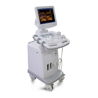
Page 33: System Introduction
System Introduction Introduction of Each Unit (10) - Page 34 System Introduction ( 11) (12) (13) (14) Name Function <1> Monitor Displays the images and parameters during scanning <2> Control panel Operator-system interface or control <3> DVD-RW DVD-RW drive <4> Power switch Used for turning on/off the power supply <5> Video printer Space reserved for B/W thermal printer compartment...
-
Page 35: I/O Panel
System Introduction I/O Panel (13) (14) (10) (11) (15) (16) (12) Name Function (1), (2) USB ports Used for connecting USB devices System reset Reset Used for network connection Ethernet port Connects the control port of the video printer Remote control port Connects a serial port device Serial port Connects a monitor or projector... -
Page 36: Power Panel
System Introduction (15), (16) Used for audio signal output, left and right track Audio output port Power Panel Name Function <1> Used for equipotential connection Equipotential terminal <2> Power inlet AC power inlet <3>, <4> Auxiliary power outlets Supply power for optional peripheral devices (e.g. VCR) <5>... -
Page 37: Ecg Panel
System Introduction ECG Panel Name Function <1> Two USB ports Used for connecting USB devices <2> Reserved for future use. Mic In port (use for connecting microphone to record vocal comments) <3> ECG lead signal input port Used for connecting ECG leads and acquiring ECG signals <4>... -
Page 38: Control Panel
System Introduction Control Panel Name Description Function Escape Press to exit the current status to the previous status. Help Help Press to open or close the accompanying help documents. iStation Press to enter or exit the patient information management system. User-defined key You can assign a function to the key. - Page 39 System Introduction User-defined key You can assign a function to the key. User-defined key You can assign a function to the key. User-defined key You can assign a function to the key. User-defined key You can assign a function to the key. (10) Quad 4-window display...
- Page 40 System Introduction (24) Directional soft Up / down controls are used to turn pages up / menu controls down when there are more-than-one pages for the soft menu; Left / right controls are used to switch between the image modes. (25) Soft menu control Rotate to adjust the soft menu item displayed on the bottom of the screen.
- Page 41 System Introduction In the B, C or D mode, the mode indicator (38) Gain Gain light is on; rotate the knob to increase or decrease the gain of the current image in the corresponding mode. In the Duplex or Triplex mode, press the knob to switch to a mode and then rotate the knob to increase or decrease the gain of the current image in the corresponding...
-
Page 42: Symbols
System Introduction (53) Change Change Press to toggle between calipers within the same measurement. (54) Press to enter or exit the general measurement Caliper Caliper mode. (55) Multifunction knob Rotate to adjust image parameters or comment arrows. Or when the cursor is hidden, press to show the cursor. - Page 43 System Introduction Network port Parallel port Serial port Video signal port Remote control port USB port Audio signal Microphone input jack System reset Port (reserved for future use) Product serial number Manufacture date Manufacturer Authorized representative in the European Community This product is provided with a CE marking in accordance with the regulations stated in Council Directive 93 / 42 / EEC concerning Medical Devices.
-
Page 44: Set-Up & Connections
Set-up & Connections System Set-up Please read and understand the safety precautions before placing the system. Unlock the four casters. Move the system by holding the handle. When you move the system to a desired location, lock the four casters. Leave at least 20cm at the back and both sides of the system. -
Page 45: Protective Grounding
Set-up & Connections Receptacle Retaining clamp Power cord Push the retaining clamp downward to secure the power cord, as shown in the figure below. 5.2.2 Protective Grounding The power cord of the system is a three-wire cable. The grounding terminal should be connected with a power grounding cable to ensure that protective grounding works normally. -
Page 46: Equipotential Terminal
Set-up & Connections Grounding terminal 1. Do not connect the three-wire cable of the system with a WARNING: two-wire plug without protective grounding; otherwise electric shock may result. 2. Be sure to connect this system and its peripheral devices to wall receptacles, which meet the rated power requirement written on the nameplate. -
Page 47: Positioning Control Panel And Monitor
Set-up & Connections Positioning Control Panel and Monitor You can adjust height of the control panel and monitor to accommodate your operating positions. To position the control panel: Use one hand to pinch the button located at the left internal side of the handle. Use the other hand to move the control panel up or down. -
Page 48: Connecting / Disconnecting A Transducer
Only use the transducers provided by Mindray. Aftermarket transducers may result in damage or cause a fire. NOTE: If a transducer port is not used for a long period of time, please use the dustproof cover to protect the transducer port from dust;... -
Page 49: Disconnecting A Transducer
Set-up & Connections Lock 5.4.2 Disconnecting a Transducer To disconnect a transducer: Turn the locking lever 90°counterclockwise to the horizontal position. See the figure below. Unlock Pull the transducer connector straight out vertically, as shown in the figure below. Connecting / Removing a USB Memory Device DO NOT directly remove a USB memory device;... -
Page 50: Installing A Graph / Text Printer
Set-up & Connections To remove the USB memory device: Click to open the [Remove USB Device] screen. Select the memory device to be removed. Click [OK] and you can hear a sound. Remove the USB memory device. Installing a Graph / Text Printer As shown in the figure below, a graph / text printer has a power cord and data cable. -
Page 51: Installing A Video Printer
Set-up & Connections NOTE: When you install the printer’s driver, you must specify the specific path for installation; otherwise vague path may result in longer time for searching. To set up the printer: Click to select the installed printer in the list in the [Printer] page. Set it as default printer. - Page 52 Set-up & Connections Click [Peripheral Preset] to open the [Peripheral Config] screen. Click [I/O Config] tab to open the [I/O Config] page. Set output size and output mode. To print the on-screen image, press the [PRINT] button on the printer’s panel. To use [Print] key on the control panel of the system, you Connect the Remote cable in the compartment under the control panel to the REMOTE port of the printer.
-
Page 53: Connecting A Footswitch
Set-up & Connections Press [Setup] key on the control panel to show the [Setup] menu. Click [Peripheral Preset] to open the [Peripheral Config] screen. Click [I/O Config] tab to open the [I/O Config] page. Set output size and output mode. Click [Printer] tab to open the [Printer] page. - Page 54 Set-up & Connections You can set the footswitch function in the [Key Config] page. Refer to section 17.2 for details. 5-11...
-
Page 55: Power On / Off
– immediately stop scanning. If the system continues to function improperly – fully shut down the system and contact Mindray Customer Service Department or sales representative. If you use the system in a persistent improperly functioning state – you may harm the patient or damage the equipment. - Page 56 If you find anything not functioning properly, this may indicate that the system is defective. In this case, shut down the system immediately and contact Mindray Customer Service Department or sales representative. NOTE: When you start the system or switch between transducers, you will hear clicking...
-
Page 57: Powering Off The System
Power ON / OFF Powering OFF the System You need to follow the correct procedures to power off the system. In addition, after you upgrade the software or when the system is down, you need to power off and restart it. To power off your system normally: Turn off the system power switch on the left side of the system. -
Page 58: Basic Screen And Operation
Basic Screen and Operation Basic Screen The system monitor displays ultrasound images, parameters, menus and measurement results window. The following diagram maps out the different areas, such as patient information, image parameter & menu, image-in-image thumbnail, image area, thumbnail of images saved, body mark, help information &... - Page 59 Check [Gender], [Age] or [Operator] in the [Patient Info] box in the upper left corner of the screen. Manufacturer logo - The Mindray’s logo is displayed in the upper left corner of the screen. Hospital name - The name of your hospital is displayed on the screen, and can be entered through Setup →...
-
Page 60: Image Parameter And Menu Area
Basic Screen and Operation ECG icon - The ECG icon consists of heart-shaped symbol and heart rhythm value. Accession # - The accession # indicates exam number used in DICOM. 7.1.2 Image Parameter and Menu Area The image parameter and menu are both displayed in this area. When no menu is available, this area displays the image parameters of the current mode. -
Page 61: Thumbnail Area Of Images Saved
Basic Screen and Operation 7.1.5 Thumbnail Area of Images Saved This area displays the thumbnails of saved images for the current patient. 7.1.6 Body Mark Area In the body mark status, this area displays the available body marks. 7.1.7 Area of Help Information and Cursor Icon The help information area displays various help information or progress bar in the current status. -
Page 62: System Status Area
Basic Screen and Operation The soft menu items vary depending on the menu. The menu navigation will cause the change of the menu, while the change of the menu will cause the menu navigation. The soft menu items are operated respectively through the five groups of soft menu controls <1>, <2>, <3>, <5>... - Page 63 Basic Screen and Operation Composition Description The title bar is used to give a description for the content and function Title Bar of the screen. For some screens, contents are distributed across several pages. Page Tab Use the selection pointer and [Set] key to open / close the available pages.
-
Page 64: Patient Information
Patient Information Before examining a new patient, press the [End Exam] key to CAUTION: end the exam of the previous patient, update the patient ID and information, to avoid mixing data of the next new patient. To Start an Exam You can start a patient exam in the following situations: New patient information: to start a new patient exam, you have to enter the patient information first, for details, please refer to “8.2.1 New Patient Information”;... - Page 65 Patient Information To exit the "Patient Info" screen In the [Patient Info] screen, click [OK] or press the <Info> key again to save the entered patient information and exit the screen. Click [Cancel] or press <Esc> to exit the screen without saving any of the entered patient data.
- Page 66 Patient Information Enter the ID If you deselect "Auto Generated ID", you need to enter an ID. If an ID that is already existed in the system is entered, the system prompts "The ID existed, load data", you can choose to import the data. Name Enter patient name through the keyboard.
- Page 67 Patient Information Secondary to input the past history of the patient.. indications: CPT4 Code: to input the CPT4 code. CPT4 to input the CPT4 description. description: Exam specified information: ABD (Abdomen) (1) input height and weight of the patient. (2) BSA (Body surface area): after the height and weight are inputted, the system will automatically calculate the body surface area based on the formula which is set in the setup.
-
Page 68: Retrieve Patient Information From Istation
Patient Information (2) BSA (Body surface area): after the height and weight are inputted, the system will automatically calculate the body surface area based on the formula which is set in the setup. (3) BP & HR (4) RA Press (Right Atrium Pressure) VAS –... -
Page 69: Retrieve Patient Information From Worklist
Patient Information To search the patient information: 1. Select the data source of patient database, i.e. find where the system stores the patient data by default. 2. Input the searching condition: Item: including Name, ID, BOD and Exam Date, the default one is name; then enter a keyword in accordance with the Item selected. - Page 70 Patient Information Worklist screen. Query and import patient information from the DICOM Worklist server. The screen is as follows: To search the patient information: 1. Select the Worklist Server for the data source. 2. Input the searching condition: Select exam date period, click [Query] to search the patient data in the period. Enter patient ID, patient name, accession #, the system affords the result in real-time.
-
Page 71: Pause Exam & Continue Exam
Patient Information Pause Exam & Continue Exam 8.3.1 Pause Exam 1. Sometimes, you have to stop an uncompleted exam due to some special causes. When the exam is paused, the system can begin other exams. Procedures: a) Press the <Info> key to open the Patient Info screen. b) Click [Pause Exam]. -
Page 72: Activate Exam
Patient Information Activate Exam The exam that is ended within 24 hours can be activated. Specific operation: Enter iStation screen or Review screen. Select items to be activated in the list. Click [Activate Exam] and restore the exam. Tips: The system can automatically load the patient information and exam data to continue the exam. -
Page 73: Exam Types
Exam Types If the exam type is changed during a measurement, all CAUTION: measurement calipers on the image will be cleared. The data of general measurements will be lost, but the data of application measurements will be stored in the reports. Introduction of Exam Types The system can perform the following exam types: A-Abdomen - (Adult Abdomen) -
Page 74: Selecting Transducer And Exam Type
Exam Types User-defined Selecting Transducer and Exam Type Opening [Select Probe & Exam] Screen Connect a transducer. Press [Probe] key on the control panel to open the [Select Probe & Exam] screen. Selecting Transducer and Exam Type In the [Select Probe & Exam] screen as shown below, roll the trackball to move the cursor onto an exam type in a transducer column, and click [Set]. -
Page 75: Setting Exam Types
Exam Types Setting Exam Types In the [Setup] menu, select the [Exam Preset] item to enter the [Exam Preset] screen. Or Press the [Probe] key to open the [Select Probe & Exam] screen and click the [Exam Preset] button to enter the [Exam Preset] screen. Th e [Exam Preset] screen consists of two pages: Exam Selection and Exam Config. -
Page 76: Exam Configuration
Exam Types to the Exam Selected. Click to add the exams, which Exam Library has but Exam Selected doesn’t have, from Exam Library to Exam Selected. After the selected exam types are set, you can arrange the order of these exams. Select buttons to adjust the order of these exam types one by one. -
Page 77: User-Defined Exam Types
Exam Types Select a second exam and, click to paste the copied parameters to the secondly-selected exam type. Click to open the screen to store the parameters of the selected exam types. Click to open the screen to load the parameters of the exam type. Click to open the screen to store the parameters of all exam types for the current transducer. - Page 78 Exam Types Enter a new name. Click [Measure Preset] to set measurement package and attributes. Click [Comment Preset] to set comments. Click [Body Mark Preset] to set body marks. Click [Image Preset] to set images. Click [OK] button to confirm.
-
Page 79: Image Modes
Image Modes 1. The images displayed in this system are only reference WARNING: for diagnosis. Mindray is not responsible for the correctness of diagnostic results. It is the responsibility of the clinician, who performs the exam, to capture the correct diagnostic results. -
Page 80: Switching Between Image Modes
Image Modes 10.2 Switching Between Image Modes Select and Switch B Mode control: press to enter the B Mode M Mode control: press to enter the M Mode Pulsed Wave Doppler control: press to enter the PW Doppler mode Continuous Wave Doppler control: press to enter the CW Doppler mode Color Mode control: press to enter Color Mode Power Mode control: press to enter Power Mode Dual-split display key: press to enter the Dual-split display mode. -
Page 81: Image Adjustments
Image Modes 10.3 Image Adjustments Imaging adjustments are performed through the following methods: 1. Adjustments through image menus or soft menus The image menus are located on the upper left corner of the screen. To adjust: 1) Press <Set> or [Back] key; or 2) Rotate the [Multifunction] knob. -
Page 82: B Mode
Image Modes 10.3.1 B Mode Changing B image display In B Mode, you can change the display depth, flip (horizontally or vertically) images, rotate images, change the view field or magnify images. Depth To change depth: Press knob to illuminate the Depth indicator; Rotate the knob clockwise to increase the depth;... - Page 83 Image Modes FOV (Field of View) To change field of view: Click [FOV] item in the menu; Select among four selections W, M1, M2, and N. B Steer The B Steer feature is valid only for linear transducers. Click [B Steer] item in the menu to select among B steer angles. Optimizing B image You have the ability to optimize the patient examination through parameter changes.
- Page 84 Image Modes Focus Number and Focus Position To make the beams closer in the region of interest: Increase the number of focal zones; Or move the position of the focal zones. The focus position symbol is displayed on the right side of the image. To change focus number or focus position: Click [Focus Number] or [Focus Position] item in the menu.
- Page 85 Image Modes Persistence Persistence is used to remove image noise and improve the overall image quality. Click [Persistence] item in the menu. Select between 0 and 7. TSI (Tissue Specific Imaging) This feature is used to adjust the speed of sound against various tissue types, i.e., General, Muscle, Fluid and Fat.
-
Page 86: M Mode
Image Modes Gray Rejection The Gray Rejection feature processes and rejects gray scale levels within certain ranges. Click the [Rejection] item in the B image menu or soft menu, and the Gray Rejection toolbox will appear . Move the cursor onto the ▲ marker. The cursor becomes a . - Page 87 Image Modes Time Mark To turn on or off time line markers in the M Mode, click [Time Mark] item in the menu to select [On] or [Off]. Speed This function is used to increase or decrease the M Mode sweep speed. Click [Speed] item in the menu.
- Page 88 Image Modes Focus Position Click [Focus Position] item in the menu. Change the position of focal zones. The focus position symbol is displayed on the right side of the image. Dynamic Range The Dynamic Range function is used to adjust contrast resolution of the B Mode image to compress or expand the gray display range.
-
Page 89: Color Mode
Image Modes 10.3.3 Color Mode Color Mode is used to detect blood flow information throughout the body. The system will display an onscreen color bar graphic indicating flow direction towards and away from the transducer. In addition, the system indicates blood flow velocity. According to the Color scale selection, increased / high flow will display brightly, low / slow flow will display darkly. - Page 90 Image Modes Acoustic Power The acoustic power refers to ultrasound power transmitted from the transducer. You should perform exams according to actual situation and ALARA Principle. Click [A. Power] item in the menu to select among percentages. The AP value is also displayed at the top of the screen. B Image Display Click [B Image Display] item in the menu.
- Page 91 Image Modes Packet Size This feature is used to adjust the accuracy of color flow. Click [Packet Size] item in the menu. Select among 0, 1, 2 and 3. Color IP Click [Color IP] item in the menu. Select among 1 through 8. The Color IP value selected is also displayed in the image parameter area.
-
Page 92: Power / Dirpower Mode
Image Modes Focus Position This feature is used to adjust the color focus position relative to the B focus. Click [Focus Position] item in the menu. Select among 0% through 100% in increments of 10%. When the position is changed, the transmit focusing delay changes accordingly. 10.3.4 Power / DirPower Mode Fundamental Power Mode is a non-directionally display of blood flow in the form of intensity as opposed to flow velocity. - Page 93 Image Modes iTouch After you press the [iTouch] key on the control panel, the system will automatically set the PW baseline and PRF value to the optimum settings according to the current scanned tissue characteristics. To preset the one-key optimization, Press [Setup] key on the control panel to show the [Setup] menu.
- Page 94 Image Modes Baseline This feature is used to accommodate the flow with quicker or slower speed to eliminate alias. Click [Baseline] item in the menu. Select [Baseline] among 4 through -4. This feature is used to adjust the width of Sample Volume gate in the PW mode. Click [SV] in the menu.
- Page 95 Image Modes Speed Click [Speed] in the menu. Select [Speed] value. Acoustic Power The acoustic power refers to ultrasound power transmitted from the transducer. You should perform exams according to actual situation and ALARA Principle. Click [A. Power] item in the menu to select among percentages. The AP value is also displayed at the top of the screen.
- Page 96 Image Modes Auto Calc (Auto Calculation) Click it in the menu to turn on or off the auto calculation. When it is On, the system will display the Doppler waveform according to the parameters set in the Auto Spectrum Calculation. When it is Off, the auto calculation status is exited and the result disappears from the result window.
-
Page 97: Image Magnification
Image Modes HPRF (High Pulse Repetition Frequency) HPRF mode is used when detected velocities exceed the processing capabilities of the currently selected PW Doppler scale or when the selected anatomical site is too deep for the selected PW Doppler scale. Click [HPRF] item in the menu. -
Page 98: Image Parameter Preset
Image Modes c) Select “iZoom” in the Other page. d) Click [OK] to complete the setting. (2) Open the image (or the under scanning image), press the defined iZoom key to zoom in the area in the first type; press the key again to zoom in the area in the second type. - Page 99 Image Modes The [A-Abdomen - All Probe] field on left side of the screen displays the parameter setup for all transducers in A-Abdomen exam type. The [A-Abdomen - 3C5A] field on the right side of the screen displays parameter setup for the 3C5A transducer in A-Abdomen exam type. The operation of the image parameter setup uses the drop down menus to make numerous selections.
- Page 100 Image Modes B Gray Map and THI Gray Map Click [B Gray Map] or [ THI Gray Map ] on the left field to enter the settings of gray map, as shown in the figure below. R efer to the relevant B Mode chapter for adjustment of post processing curves. The system can store 8 different post processing maps, which are selectable through the image menu.
-
Page 101: Special Imaging Modes
Special Imaging Modes The system supports the optional imaging modes as follows: 3D/4D iScape Free Xros M NOTE: 1 The ultrasound images, specially obtained in the 3D/4D mode or iScape mode, are provided for reference only, not for confirming a diagnosis. Please use caution to avoid misdiagnosis. -
Page 102: Overview
Special Imaging Modes 11.1.1 Overview Ultrasound data based on three-dimensional imaging methods can be used to image any structure where a view can’t be achieved by standard 2D-mode to improve understanding of complex structures. This system supports Smart3D, Static 3D and 4D imaging modes. 4D provides continuous, high volume acquisition of 3D images. - Page 103 Special Imaging Modes 11.1.1.2 ROI & VOI Before image acquisition after the system enters 3D/4D mode, a B image with ROI displays on the screen. A broken line (shown in the following figure) that shows the upper edge position of VOI is inside ROI; its length is the same as the width of ROI. ROI size and position Roll the trackball to change the ROI size and position, press the <Set>...
- Page 104 Special Imaging Modes 11.1.1.3 3D view direction The Region of Interest (ROI) contains the section of the volume you want to render. You can adjust the view direction of the ROI. The system supports to view the 3D/4D image from six different directions. View Direction a.
- Page 105 Special Imaging Modes 11.1.1.4 Sectional Plane The principle of 3D imaging is to restructure a 3D image from multiple 2D image information. The following describes the spatial relation of 3 sectional planes (A, B and C) and the 3D image. The sectional plane can be viewed in the following statuses.
- Page 106 Special Imaging Modes A, B, C sectional images are corresponding to the following sections of 3D image. Section A: correspond to the 2D image in B mode. Section A is the sagittal section in fetal face up posture, as shown in the figure A above. Section B: it is the horizontal section in fetal face up posture, as shown in the figure B above.
- Page 107 Special Imaging Modes Section A Section B Section C E.g. select A as the current window and roll the trackball, section lines (indicating the position of A) in the B and C window move, and image in A window changes. 11.1.1.6 Mode definition The system supports three 3D imaging modes: Smart3D, Static 3D and 4D, all of them are target for 3D imaging, however, differences exist.
-
Page 108: Note Before Use
Special Imaging Modes 11.1.2 Note before Use 11.1.2.1 3D/4D Image Quality Conditions The quality of images reconstructed in the 3D/4D mode is closely related to the fetal condition, angle of a B tangent plane and scanning technique (only for Smart3D). The following description uses the fetal face imaging as an example, the other parts imaging are as the same. -
Page 109: 4D Setup
Special Imaging Modes Evenness: Move or rotate the transducer at a steady speed or rate. A region with qualified image in B mode may not be optimal for CAUTION: 3D/4D imaging. E.g. adequate AF isolation for one section plane doesn’t mean the whole desired region is isolated by AF. More practices are needed for a high success rate of qualified 3D/4D imaging. - Page 110 Special Imaging Modes 11.1.3.3 Parameters Setup Open the 3D/4D Image Preset interface via 『Setup』key [Setup] [Image Preset] [3D/4D], you can set parameters to your preference. The main presetting page is shown as follows: Select the probe Select a probe model in the drop-down list General parameters setup Disp Format: to set the image display format in 3D image viewing status.
- Page 111 Special Imaging Modes 1. Name: move the cursor to the Name column and change the preset package name by the keyboard. 2. General parameters preset: Render: select image rendering mode Render type: select the imaging mode Direction: select 3D view direction Quick Rot.: set the angle for quick rotation.
-
Page 112: Enter/ Exit 3D/4D
Special Imaging Modes 11.1.4 Enter/ Exit 3D/4D Entering Press F2 shortcut key to enter 3D/4D acquisition preparation mode; or In B mode, click [3D/4D] in the soft menu; or, Press the [Menu] key in any exam mode, select [Other] [3D/4D] in the displayed menu to enter 3D/4D acquisition preparation mode. - Page 113 Special Imaging Modes Click [3D/4D] soft menu in B mode; or, Move the cursor onto the menu title (of image menu or biopsy menu), other selections pop up, navigate the cursor to [Other] item and press <Set>. Select [3D/4D] in the Other menu to enter the 3D/4D mode. Switch to Smart3D mode by clicking [3D/4D] item, and define the ROI and curved VOI.
- Page 114 Special Imaging Modes Parameters setting Parameters description: Type Parameter Description Start Function: to begin image acquisition. Acquisition Stop Function: to stop image acquisition. Function: to select 3D image view direction. Selection: U/D, D/U, L/R, R/L, F/B, B/F. Direction The general direction is U/D, For the detailed definition; please refer to “11.1.1.3 3D view direction”.
- Page 115 Special Imaging Modes Type Parameter Description Exit Exit Exit 3D/4D mode. 11.1.5.3 Smart3D Image Acquisition The following takes the fetal face 3D imaging as an example. Optimize the 2D image of the desired region. Make sure: High contrast between the desired region and the AF (amniotic fluid) surrounded. Clear boundary of the desired region.
- Page 116 Special Imaging Modes Perform the capturing according to the scanning technique stated above. (Take fan scanning as an example). Press [Update] key again or [Freeze] key or click [stop] to end the acquisition, or wait until the memory is full and the system automatically ends the acquisition. Viewing and adjusting 3D image.
- Page 117 Special Imaging Modes Parameter Description Disp Format Function: to set the image display format in 3D image viewing mode. Function: to enter cut function. Function: to set Surface as 3D image rendering mode. This is helpful for surface imaging, such as fetus face/hand Surface or foot.
- Page 118 Special Imaging Modes Parameter Description To quick rotation the 3D image. Quick Rot. Selection: 0°, 90°, 180°, 270°. Direction To set the fast view direction when entering viewing mode. Reset Curve To reserve the VOI edge line to be plane. Auto Rotation Function: to open 3D image auto rotation function.
- Page 119 Special Imaging Modes Select [Single], system displays one image, which can be a sectional image or a 3D image. Select [Dual], system displays two images left and right. (The left one can be section A, section B or section C image, and the right one is 3D image.) Select [Quad], system displays four images.
- Page 120 Special Imaging Modes Scanning plane and the transducer movement Arrow in the figure below indicates the movement of the transducer, (you can move the transducer in the contrary direction of the arrow.) Adjust VOI Function Adjusting the VOI box size, VOI position and curved VOI is to select the volume data needed to render the 3D image and improve rendering effect.
- Page 121 Special Imaging Modes Sphere center rotation Rotate the 3D image around the center point of the 3D image. Procedures a) Set 3D image window as the current window. Click [Current Window] to “3D” on the menu; or, press [Cursor] on the control panel to show the cursor, then move the cursor onto 3D image window, and press <Set>...
- Page 122 Special Imaging Modes Quick Rotation Click [Quick Rot.]; the 3D image will rotate by 90° every step. Image Resetting The 3D image returns to the initial status if you click [Reset] on the soft menu, in rotation mode except auto rotation. Image zooming Function Adjust the zoom factor of 3D image, the section images will be zoomed in/out...
- Page 123 Special Imaging Modes Select an editing tool. Set edit depth. Roll the trackball and press the <Set> key to position the start point, roll the trackball to set a region and press the <Set> key again, the selected region will be cut from the 3D rendered image.
- Page 124 Special Imaging Modes Type Parameter Description Function: to define the depth to cut. 3D image changes in real time along with the depth. Selection: Full Depth, Edit Depth. Cut Depth Depth Full Depth: the entire depth of the selected region will be cut. Edit Depth: to define the depth to cut.
- Page 125 Special Imaging Modes 3 image acquisition parameters: Method, Distance, Angle or Reset Curve, their functions and adjusting method are the same as the parameters in “Smart3D Acquisition Preparation”. 3 image viewing parameters: Set First Frame, Set End Frame. Auto Play, their functions and adjusting method are the same as the parameters in “Cine Review”.
- Page 126 Special Imaging Modes the menu according to your preference. Tip: To adjust the image quality by changing the line density. Image quality can affect the imaging speed that the better the image quality, the lower the speed, so the frame rate is lower. Click [Start];...
- Page 127 Special Imaging Modes 11.1.6.3 4D Image Acquisition Procedures: Optimize the 2D image of the desired region. Make sure: High contrast between the desired region and the surroundings. Clear boundary of the desired region. Little noise. Set ROI (Region of Interest) on the 2D image. Roll the trackball to change the ROI size, ROI position and curved VOI, press the <Set>...
- Page 128 Special Imaging Modes Set the brightness, contrast, smoothness and colorize map for 4D image. Rotate, zoom in/out and shift the 4D images, and reset the images to original status by clicking [Reset]; surface data and 4D images review. View the sectional images. 4D image cutting.
-
Page 129: Static 3D
Special Imaging Modes 11.1.7 Static 3D 11.1.7.1 Procedures for Static 3D Imaging Select the appropriate 4D-compatible probe and connect it to the ultrasound system (the leftmost port). Make sure there is sufficient gel on the probe for scanning. Tip: if the current probe doesn’t support Static 3D imaging, then [Static 3D] menu item is disabled when entered 3D/4D mode. -
Page 130: Iscape
Special Imaging Modes 11.1.7.2 Static 3D Acquisition Preparation Parameters setting Adjustable parameters in static 3D acquisition preparation status are the same as that of 4D acquisition preparation, for details; please refer to the corresponding contents in “11.1.6.2 4D Acquisition Preparation”. 11.1.7.3 Static 3D Image Acquisition Static 3D image acquisition operations are basically similar with that of 4D, the only difference is: in static 3D mode, only a single frame 3D image captured, while in 4D mode,... -
Page 131: Enter Or Exit Iscape
Special Imaging Modes 11.2.1 Enter or Exit iScape To enter iScape mode, Move the cursor onto [iScape] item in the Other menu, and press <Set> key; To enter the iScape mode via a user-defined key, Assign a key (F1 through F10, or left & right keys of footswitch) as user-defined iScape panoramic imaging. -
Page 132: Review The Captured Images Frame By Frame
Special Imaging Modes Magnify extended image In the iScape Review mode, Press knob to illuminate the Zoom indicator and enter the zoom status. Rotate the knob to change the magnification. Roll the trackball to change position of the magnified image. Press knob again or [Esc] key to exit the zoom mode. -
Page 133: Save And Open Images
Special Imaging Modes Move the cursor onto the start of the cine loop, click [Set First Frame] in the menu to set the start point. Move the cursor onto the end of the cine loop, click [Set End Frame] in the menu to set the end point. -
Page 134: Enter/ Exit Free Xros
Special Imaging Modes 11.3.2 Enter/ Exit Free Xros Enter Free Xros M In B mode or B+M real-time scanning mode, click [Free Xros M] in the soft menu, or press the user-defined key directly. Exit In Free Xros M mode, click [Free Xros M] in the soft menu or press <B> or the user-defined key to exit. - Page 135 Special Imaging Modes During real-time Free Xros M imaging, menus for B mode and Free Xros M mode are displayed in the soft menu at the same time, use the left/right keys of soft menu controls <4> to switch the menus of B mode and Free Xros M mode. Parameters consistent with those in M mode are not to be introduced, please refer to relevant section of the M mode, while special items of the Free Xros M mode will be introduced in the following.
-
Page 136: Cine Review
Cine Review After you press the [Freeze] key, the system allows you to review and edit the images prior to the image frozen. This function is called as cine review. The magnified images can also be reviewed after the [Freeze] key is pressed, and the operating method is the same. You can change post processing maps, perform measurements, add comments and body marks on the images being reviewed. -
Page 137: Auto Cine Review
Cine Review When you review images until the first or the last frame, further rolling the trackball will display the last or first frame. The cine progress bar at the bottom of the screen (as shown in the figure below): the whole bar represents the total frame number. -
Page 138: Setting Region Of Auto Review
Cine Review 12.5 Setting Region of Auto Review You can set a segment of cine loop which can be reviewed automatically. After the auto review region is set, the auto cine review can only be performed within this region; but the manual cine review can be performed beyond this region. -
Page 139: Cine Setup
Cine Review 12.7 Cine Setup 12.7.1 Setting Cine Length You can set the cine length in the system setup screen. Enter the system setup screen, and open the [General] page. In the Storage field, the Cine Length item is located in the middle, as shown in the figure below. -
Page 140: Measurements
Measurements Be sure to measure areas of interest from the most WARNING: optimal image plane to avoid misdiagnosis from inaccurate measurement values. To obtain accurate Doppler flow measurement values, make sure the transmitting beam is not perpendicular to the flow, otherwise false readings and potential misdiagnosis may result. -
Page 141: Measurement Result And Help Information
Measurements 13.1.2 Measurement Result and Help Information The system displays and updates measurement results in the result display area. The Help information concerning measurement and calculation is displayed in the Help bar at the bottom of the screen. 13.2 General Measurements 13.2.1 General Measurements –... -
Page 142: General Measurements - M Mode
Measurements 13.2.2 General Measurements - M Mode The measurements listed below can be performed in the M Mode: Measurement tool Function Distance The vertical distance between two points. Time The time interval between any two points. Slope The slope is calculated by means of measuring the distance and time between two points. -
Page 143: Application Measurements
Urology measurements - Used for prostate, seminal vesicle, renal, adrenal, micturated and testicle volume. Orthopedics measurements - Used for hip joint measurement (only used for the system DC-3). Peripheral vessel measurements – Used for carotid, cerebral, upper and lower extremities vessels, etc. -
Page 144: Comments (Annotations)
Comments (Annotations) You must ensure that the entered comments are correct. WARNING: Incorrect comments may cause misdiagnosis! Comments can be added to an ultrasound image to bring to attention, notate or communicate information observed during the examination. You can add comments to: zoomed image cine review image real-time image... -
Page 145: Soft Menu For Comments
Comments (Annotations) Cardiac, GYN (Gynecology), OB (Obstetrics), Urology, SMP (Small Part), PED (Pediatrics), Nerve, EM and Vascular. To customize the comment text library, press [Setup] key to select [Comment Preset] and open the comment preset screen. After you customize the comment text library for an exam, you will see the customized comment texts when you open the comment text library menu in this exam mode. -
Page 146: Adding Comments
Comments (Annotations) Changing Language Click [English] to turn on or off the English comments. If turning on the English comments, the comments will display in English; if turning off the English comments, the comments will display in the language you set in the preset. If the current language is English, the language selection is not available. -
Page 147: Adding An Arrow
Comments (Annotations) comment item is displayed in a box, press <Set> again to add the item to the set location. 5 Or you can use an initial of a comment text to search the complete comment text. Move the cursor to the desired location for adding the comment text, and enter the initial of a comment text, then rotate the [Multifunction] knob to display the comment texts one by one. -
Page 148: Modifying (Editing) Arrows
Comments (Annotations) and type characters or select the new comment text from the comment text library menu. 4 Press the [Del] key to delete the comment character or text on the right side of the cursor. 5 Press the [Backspace] key to delete the comment character or text on the left side of the cursor. -
Page 149: Deleting All Comments (Characters, Texts Or Arrows)
Comments (Annotations) 14.6.4 Deleting all Comments (Characters, Texts or Arrows) Click [Erase All Text] to delete all the comment items on the screen. You can also assign the corresponding shortcut key for the function in “[Setup] → [System Preset] → [Key Config]”. Pressing the <Clear>... -
Page 150: User-Defined Comments
Comments (Annotations) 14.7.2 User-defined Comments You can customize user-defined comments for an exam mode according to your preferences. The customized comments will display in the corresponding exam mode. The operational steps are as follows: 1 To open the [Comment Preset] screen, select [Comment Preset] in the [Setup] menu. The following example is comment preset in A-Abdomen mode. - Page 151 Comments (Annotations) Select Available Items: First select a comment library in the drop-down list beside “Available Items”, and then click [Set] on one item displayed below “Available Items”. Click to add one item to the box on the right side. To add all items on the left side to the right side, click 5 Change the selected items on the right side: select an item on the right side box and click [Up], [Down], [Left] or [Right] button to move the position of the item.
- Page 152 Comments (Annotations) 7 After you customize comments, click [OK] to confirm and exit the [Comment Preset] screen. 14-9...
-
Page 153: Body Marks (Pictograms)
Body Marks (Pictograms) The Body Mark (Pictogram) feature is used for indicating the exam position of the patient and transducer position and orientation. 15.1 Entering / Exiting Body Mark Mode To enter the Body Mark feature, Press to enter the body mark selection mode. To exit the Body Mark feature, Press [Body Mark] again to exit the body mark mode;... -
Page 154: Adding Body Marks
Body Marks (Pictograms) 15.4 Adding Body Marks The following will describe the steps to add the first Body Mark graphic to the imaging window. Enter the Body Mark status; use the soft menu control to click [Library] to select the body mark category. -
Page 155: Moving Body Marks
Body Marks (Pictograms) 15.5 Moving Body Marks You can move the Body Mark graphic to any desired position within the image area. 1 Roll the trackball to move the cursor onto the Body Mark graphic. The cursor becomes , indicating you can move the pictogram to a new position. 2 Click the [Set] key to select the Body Mark graphic, a frame will now appear around the graphic. -
Page 156: Preset Exam Type Body Mark Preferences
Body Marks (Pictograms) 15.7.1 Preset Exam Type Body Mark Preferences 1 Select the [Body Mark Preset] item in the Setup menu and enter the [Body Mark Preset] screen (as shown in the figure below). 2 Select the exam type that you will preset the Body Mark presets from Exam Mode drop down menu. -
Page 157: User-Defined Body Marks
Body Marks (Pictograms) 15.7.2 User-defined Body Marks If there is no Body Mark pictogram from the Body Mark library, you can create a graphic of your own. In the body mark preset screen above, click to enter the user-defined body mark screen (as shown in the figure below). - Page 158 Body Marks (Pictograms) To add user-defined body marks, Click the [Add] button on the screen to enter the creation selection screen of Body Mark. Select a body mark on the current screen and click [Copy] to enter the body mark drawing screen, thus you can edit the copied body mark.
- Page 159 Body Marks (Pictograms) The drawing tools are described as follows; select from among the tools to create your own specialized graphic. Brush Eraser Up/down flip Left/right flip Zoom in Zoom out Rotate Drag You can select on the screen, to adjust position of the transducer indicator on the body mark and rotate the [Multifunctional] knob to change direction of the indicator.
-
Page 160: Patient Data Management
2. The system patient database space is limited, please back up or clear patient data in time. 3. Mindray is not responsible for lost data if you DO NOT follow suggested backup procedures. 16.1 Patient Information Management 16.1.1 Enter Patient Information The general patient information and exam information are entered through the Patient Info screen, for details;... -
Page 161: Image File Management
Patient Data Management 16.2 Image File Management You can store the image files either in the patient database in the system, or to external memory devices. For a saved image, you can perform operations like image reviewing, analyzing and demonstration (iVision). 16.2.1 Memory Media System supported memory media including: System hard disk... -
Page 162: Image Storage Preset
Patient Data Management Single-frame file format, used to save the current screen in the compressed format; you can set the compression ratio. TIFF: Single-frame export format Multi-medium files (AVI) Multi-frame file format, general cine file format. DICOM files (DCM) DICOM standard files format, single-frame or multi-frame format, used to record patient information and images;... -
Page 163: Quickly Saving Images To Usb Flash Drive
Patient Data Management select “Send Single Frame Image to Local Disk” in the Output page of Function field on the right side. 2. Press the user-defined key to save the image. In the image screen, press the user-defined key to save the current single-frame image, and the image is saved with the default file name in the default file directory in the FRM format. -
Page 164: Quickly Saving Full Screen Image To The System
Patient Data Management 16.2.6 Quickly Saving Full Screen Image to the System This function can save the current full screen image to the system with image in scanning mode. 1. Set the user-defined key through the path: [Setup] (by pressing <Setup>)→ [System Preset]→... - Page 165 Patient Data Management To exit Review: Click [Exit] on the Review screen; or, Press <ESC> or <Review> again. Basic operations Select an exam item in the Exam History area. The selected item is highlighted. Click [Info] or [Report] to view patient information or report. Double-click a thumbnail to view and analyze an image.
-
Page 166: Ivision
Patient Data Management [Send To]: click to send the selected image to other location, DICOM server, printer and etc. [Delete]: click to delete the selected image. Layout: You can select the layout of the Review screen among three selections: 1×1, 2×2 and 4×4. - Page 167 Patient Data Management 3. Select an item in the list, and click [Start] to begin the demonstration. 4. Click [Exit] or press <ESC> to exit the iVision status. The iVision screen is shown as follows: Demonstration item The demonstration items are the image files in the formats that the system supports. You can add the exam data in patient database or system supported image files and folders to demonstration list.
-
Page 168: Sending Image File
Patient Data Management [Delete]: to delete the selected file or catalog in the file list. [Clear]: to clear all the files or catalogs in the file list. Demo mode Interval: refer to the interval time for demonstration, the adjusting range is 1~500s. Option of Demo You can choose whether to repeat the demonstration or exit after a demonstration is completed. -
Page 169: Report Management
Patient Data Management 16.3 Report Management Report storage: The exam reports are stored under the directory of the exam of the patient. Importing, exporting and sending a report 1. In the iStation screen, select patient data, click [Restore] or [Backup] to import or export patient information, images and reports from or to an external memory device. -
Page 170: Patient Data Management (Istation)
Patient Data Management 16.4 Patient Data Management (iStation) The patient data include basic patient information, exam information, image files and reports. You can search, view, backup, send, restore or delete patient data in iStation. To enter iStation: Press the <iStation> key on the control panel; or Click the [iStation] button in the Patient Info screen;... -
Page 171: Searching A Patient
Patient Data Management Select All/Deselect All Click [Select All] to select all the patient data listed. Then the button changes into [Deselect All], you can cancel all the selections by clicking [Deselect All]. 16.4.2 Searching a Patient 1. Select the data source. 2. -
Page 172: Examinations
Patient Data Management Recycle bin The recycle bin is used to store the deleted patient data, exam data and images (time lasts from deleting to system is powered off). The system supports recovery of those data from the recycle bin. Tips: The recycle bin will be cleared after the system is powered off. -
Page 173: Network Storage
Patient Data Management 16.5 Network Storage Network storage is used to save image files and measurement reports to the remote PC server. 16.5.1 Network Storage Setting Open “[Setup]→[Network Preset]→[Network Storage]” to perform network storage setting. Name Description Service Name Name of the device, cannot be empty Destination Name of the device, cannot be empty Device... -
Page 174: Network Storage
Patient Data Management directory. And if the user name or the password is incorrect, the server cannot be entered. Click it to add the Network service to the service list. Cancel Click to cancel parameter setting Update To save the changed parameters. To set default To set as the default server for network storage server... -
Page 175: Backing Up And Erasing Files Through Dvd Drive
Patient Data Management After the printer is successfully connected and print job is undergoing, click the printer icon in the lower right corner of the screen to open the Print Task Manager screen. Information of all print tasks is displayed in the list, including ID, name, status (being printing or suspended), and submit time. -
Page 176: Task Manager
Patient Data Management 2. Select the data to be backed up, click [Send To] or [Backup] button in the screen (such as the [iStation] screen).Select the target drive in the Send To or Back Up Patient Record dialogue box. 3. Click [OK] or [Backup] button in the file-exporting screen. 4. - Page 177 Patient Data Management The system supports three types of task management: Storage Task: displays the DICOM storage task. Print Task: displays the DICOM print task. Media Storage Task: DICOM media storage task (including disc and USB devices). Backup task (system-relevant format): select the exam to be backed up in iStation and click [Backup].
-
Page 178: Reviewing The Avi Files
Patient Data Management When the task management icon displays as , it means no task is undergoing or failure. 16.9 Reviewing the AVI Files To review the AVI files, which are stored in the ultrasound system, in the environment of PowerPoint in a PC, you will perform the following operations to ensure the quality of images: On the PowerPoint screen, select [Media Player], and then select: View →... -
Page 179: Add/ Delete A User
Patient Data Management Log on the system: 1. If the system requires you to log on the system before you access the data, you can see the following dialogue box. 2. Select the user name in the drop-down list of User Name. 3. - Page 180 Patient Data Management 2. Click [Add] to enter the following page. 3. Enter the user name (you are not allowed to enter the same name or modify the name already exist). 4. Enter the password and the confirmed password (the password is consist of 6-16 characters) 5.
-
Page 181: Modify Password
Patient Data Management 2. Select the user to be deleted in the User List (current operator, admin and Emergency user can’t be deleted), click [Delete] to delete the selected user. 16.10.5 Modify Password The system administrator can modify password of all users. The administrator password by factory is empty;... - Page 182 Patient Data Management 3. Enter the previous and the new password in the dialogue box. 4. Click [OK] to exit. 16-23...
-
Page 183: Parameter Setup
CD or USB memory devices. When the setup data is changed, be sure to save the preferences CAUTION: according to the methods described in this chapter. Mindray is not responsible for the loss of the setup data. 17.1 Entering / Exiting Setup To enter the setup status, Press the [Setup] key on the control panel;... - Page 184 Parameter Setup To confirm the modified parameters, click [OK]. To cancel the modified parameters, click [Cancel]. Click the [Load Factory] button to restore the current page to the factory settings. The content of each page is described as follows. Region The [Region] page is to set up hospital information, logo setting, language, time zone, time format, date format, system date and system time.
- Page 185 Parameter Setup Type Function Description Standard Print (P5) Used for digital graph/text print Save Single-frame Image to To save a single frame image to the Local Disk system in the system-relevant format. To save a cine to the system in the Save Cine to Local system-relevant format.
-
Page 186: Exam Mode Preset
Parameter Setup Type Function Description iZoom To enter/ exit full-screen zoom status. iVision To enter/ exit iVision. Physiological Signal Display/ Hide the ECG menu Biopsy The [Biopsy] page is used for setup of the default bracket for a transducer and the biopsy guide line dot type or to set if the guide line is visible. -
Page 187: Soft-Key And Menu Preset
Parameter Setup 17.8 Soft-Key and Menu Preset You can preset parameter items in image modes for all types of transducers, in the soft menu (displayed at the bottom of the screen) and the menu (displayed on the upper left side of the screen), as well as parameter items for 3D capture, 3D review, PW mark, Reset ROI. - Page 188 Parameter Setup Available Items on the left side: You can select these items and move them to the [Softkey] page the right side. Items in the [Softkey] page on the right side: These items will display in the menu. Delete items from the soft menu To delete one item: Move the cursor onto an item in [Softkey] page on the right side, which is highlighted, click [Set], and then move the cursor onto click [Set].
-
Page 189: Peripheral Setup
Parameter Setup Add or delete an item To add an item to the image menu, select an item in the Available Items box and click . This item will display in the image menu. To delete an item from the image menu, select an item on the right side box and click . - Page 190 Parameter Setup 1. Add a printer For the digital video printers aforementioned in the Chapter 3.4, you do not need to install them. For the printers not mentioned, you need to install them. Click [Add Printer] to open the screen and select the printer driver (with postfix name INF) in the specified location and click [OK].
- Page 191 Parameter Setup If the Remote cable is connected to the port in the I/O panel, select [Back Port Select]. Set Up Recorder In the [Peripheral Config] screen, click Recorder to open the [Recorder] page. The system supports DVR and VCR. See the figure below. 17-9...
- Page 192 Parameter Setup DVR Settings Settings Available Selections Svideo Input Channel CVBS Output Mode NTSC HQ (1 hr.): high quality; one hour recorded for a disc SP (2 hr.): standard play; two hours recorded for a disc Record Quality EP (4 hr.): extended play, equivalent to VHS; four hours recorded for a disc LP (6 hr.): long play, equivalent to VHS;...
-
Page 193: Network Preset
The operating methods are the same as those mentioned above. 17.12 Maintenance The [Maintenance] item is designed for you to update the system software or other special functions. If you require these functions, please contact Mindray Customer Service Department or sales representative. 17-11... -
Page 194: System Information
Parameter Setup Through the menu, you can perform net update, remote desktop, system test, log operation, etc. 17.13 System Information Select the [About] item in the Setup menu to enter the system information screen, which displays the system software version and versions of other devices. You cannot edit the information but can only view them. -
Page 195: Probes And Biopsy
Probes and Biopsy Note: For details of storage time and condition for disinfected probes or sterilized probes and brackets, please refer to Technical standard for Disinfection of Medical and Health Structures 18.1 Probes The system supports the following probes: Probe Model Illustration 3C5A 6CV1... - Page 196 Probes and Biopsy Probe Model Illustration 10L4 6LB7 6LE7 7LT4 18-2...
- Page 197 Probes and Biopsy Probe Model Illustration D6-2 D6-2A 18-3...
-
Page 198: Name And Function Of Each Part Of The Probe
Probes and Biopsy 18.1.1 Name and Function of Each Part of the Probe The basic structures and corresponding functions of probes are basically the same; the following will take probe 3C5A as an example. <2> <1> <3> <4> <5> Name Function <1>... - Page 199 Probes and Biopsy 6LE7 transducer: <2> <1> <3> <4> <5> <6> Name Function <1> Transducer head It utilizes the piezoelectric effect to convert electrical signals into ultrasound waves, which are transmitted to the body, and to generate electrical signals when receiving the reflected ultrasound waves (echoes).The lens on the surface is the acoustic lens.
- Page 200 Probes and Biopsy 6LB7 transducer: <3> <2> <1> <5> <4> <6> <4> <7> Name Function It utilizes the piezoelectric effect to convert <1> <1>Transducer head electrical signals into ultrasound waves, which (convex) are transmitted to the body, and to generate <2>...
-
Page 201: Procedures For Operating
Probes and Biopsy 18.1.2 Orientation of the Ultrasound Image and the Probe Head The orientation of the ultrasound image and the probe are shown as below. The “Mark” side of the ultrasound image on the monitor corresponds to the mark side of the probe. Check the orientation before the examination (Here takes linear probe as an example). - Page 202 Probes and Biopsy Inspection before examination Connection to the ultrasonic diagnostic system Examinations Biopsy procedure Disconnection to the ultrasonic diagnostic system Sterilization of the needle- guided bracket Wiping off the ultrasound gel Inspection after use Washing the transducer with water Storage Draining/drying Immersion into disinfectant...
- Page 203 Probes and Biopsy Procedures for operating (with no biopsy function): Inspection before examination Connection to the ultrasonic diagnostic system Examinations Disconnection to the ultrasonic diagnostic system Wiping off the ultrasound gel Washing the transducer with water Draining/drying Disinfection Immersion into disinfectant Removing the transducer from disinfectant Rinsing the transducer into sterile water...
-
Page 204: Wearing The Probe Sheath
Probes and Biopsy Disinfect the probe and sterilize the needle-guided bracket before and after an ultrasound-guided biopsy procedure is WARNING: performed. Failure to do so may cause the probe and the needle-guided bracket become source of infection. 18.1.4 Wearing the Probe Sheath A legally marketed probe sheath must be installed over the probe before performing intra-cavitary and intra-operative examination. -
Page 205: When The Immersion Method Is Used (For 6Lb7 And 6Le7)
Probes and Biopsy 3. Secure the sheath with enclosed elastic 4. Inspect the sheath to ensure there is bands. no hole or tear. 18.1.5 When the Immersion Method is used (for 6LB7 and 6LE7) The transducer manufacturer recommends a syringe: CIVCO 610-224. Here takes transducer 6LB7 as an example to introduce the immersion method. - Page 206 Probes and Biopsy 1. Put on the transducer cover. For the procedures of putting on the transducer sheath, refer to subsection above. Check the transducer sheath for wrinkles and gaps. 2. Fill syringe with sterile water and connect extension tube to syringe, discharge all air in the tube.
- Page 207 Probes and Biopsy 4. Orientate the transducer upward to discharge air in the transducer cover. 18-13...
- Page 208 Probes and Biopsy 5. Turn the valve of the syringe to the position shown in the right figure, and then push the plunger of the syringe to discharge the air. 6. Return the valve of the syringe to the original position; orientate the transducer downward to discharge sterile water.
-
Page 209: Probes Cleaning And Disinfection (Or Sterilization)
Chemical residues on the probe may be harmful to the human body. 3. The efficacy of disinfectants and sterilizing solutions is not guaranteed by MINDRAY. Contact the manufacturers for information on the activity of the products. NOTE: 1. - Page 210 Probes and Biopsy Glutaraldehyde-based disinfectant: Chemical Trade Name Procedures Name Cidex Activated Glutaraldehyde Please refer to the instructions provided by the Dialdehyde manufacturer of the solution for details. (2.4%) Solution Non-glutaraldehyde based disinfectant: Chemical Name Trade Name Procedures Ortho-Phthalaldehyde Please refer to the instructions provided by the Cidex OPA (0.55%) manufacturer of the solution for details.
- Page 211 For intra-operative probes (7LT4), they have to be sterilized after completing each examination. 1. Wear sterile gloves to prevent infection. 2. Clean the probe before sterilizing it. MINDRAY recommends the following solutions to sterilize the probe. Hydrogen Peroxide and Peroxyacetic Acid -based sterilization solution...
-
Page 212: Storage And Transportation
2. Store and transport the probe under the specified ambient conditions. 3. When the probe is sent to MINDRAY Customer Service Department or sales representative for repair, be sure to disinfect it and keep it in the carrying case to prevent infection. - Page 213 If an abnormality is found on the needle-guided bracket, immediately stop using it and contact MINDRAY Customer Service Department or sales representative. 4. DO NOT use a needle-guided bracket when scanning is performed.
-
Page 214: Needle-Guided Brackets
A needle-guided bracket is available for purchase as an optional accessory; it is used in combination with the probe. Some of the probes have matched needle-guided bracket and needles. To order needle-guided brackets, contact MINDRAY Customer Service Department or sales representative. - Page 215 Probes and Biopsy NGB-004 Locking nut Retaining clamp Needle guide Locating bulge Locating groove Probe 18-21...
- Page 216 Probes and Biopsy NGB-005 Clamping knob of the needle guide Needle guide rack Needle guide Clamp Locating pit Locating pit Needle guide hole Grip knob Locating groove Needle-guided bracket Probe NGB-006 Metal/needle detachable needle-guided bracket: 18-22...
- Page 217 Probes and Biopsy Name Description <1> Support of Used for installing the needle-guided bracket on the probe. needle-guided bracket <2> Groove and tab of Respectively matched with the tab and groove of the the needle-guided probe. bracket <3> Angle adjusting There are 3 types of angles available to be adjusted.
- Page 218 Probes and Biopsy Plastic/needle detachable needle-guided bracket: Name Description Support of Used for installing the needle-guided bracket on the <1> needle-guided probe. bracket Used for determining the angle of the biopsy; there are <2> Angle block three specifications of blocks of angle. Used for installing biopsy needle;...
- Page 219 Probes and Biopsy NGB-007 Metal/needle detachable needle-guided bracket: Name Description Support of Used for installing the needle-guided bracket on the <1> needle-guided probe. bracket Groove and tab of Respectively matched with the tab and groove of the <2> the needle-guided probe.
- Page 220 Probes and Biopsy Plastic/needle detachable needle-guided bracket: Name Description Support of <1> needle-guided Used for installing the needle-guided bracket on the probe. bracket Used for determining the angle of the biopsy; there are <2> Angle block three specifications of blocks of angle. Used for installing biopsy needle;...
- Page 221 Probes and Biopsy NGB-008 Plastic/needle-detachable needle-guided bracket: <6> <5> <3> <2> <7> <1> <4> Name Description Support of Used for installing the needle-guided bracket <1> on the transducer needle-guided bracket Used for determining the angle of the biopsy; <2> Angle block there are two specifications of blocks of angle Used for installing biopsy needle;...
- Page 222 Probes and Biopsy Metal/needle-detachable needle-guided bracket: <2> <8> <1> <6> <7> <4> <10> <9> <5> <3> Name Description Clamp of needle-guided Used for installing the needle-guided bracket on <1> bracket the transducer Groove and tab of Respectively matched with the tab and groove of <2>...
- Page 223 Probes and Biopsy NGB-009 Name Description <1> Support of Used for installing the needle-guided bracket on the transducer needle-guided bracket <2> Knob fixing Used for fixing the needle-guided bracket on the needle-guided bracket transducer <3> Groove Match with the tab on the transducer <4>...
- Page 224 Probes and Biopsy NGB-010 Name Description Used for installing biopsy needle; there are five Guiding block specifications of guiding blocks for different biopsy needles. Guiding hole of the Used for installing the biopsy needle. biopsy needle Support of Used for installing the needle-guided bracket on the needle-guided probe.
- Page 225 Probes and Biopsy NGB-011 Needle guide Clamping knob of the needle Locating pit Clamp Needle guide hole Locating groove Grip Needle guide rack knob Needle-guided bracket Probe 18-31...
- Page 226 Probes and Biopsy NGB-012 Metal/needle detachable needle-guided bracket: Name Description Support Used for installing the needle-guided bracket on the <1> needle-guided transducer bracket Groove and tab of Respectively matched with the tab and groove of the <2> needle-guided transducer bracket Angle adjusting <3>...
- Page 227 Be sure to perform inspections before and after use of the needle-guided bracket. If an abnormality is found on the needle-guided bracket, immediately stop using it and contact MINDRAY Customer Service Department or sales representative. 1. Sterilize the needle-guided bracket before and after use.
- Page 228 Probes and Biopsy 18.2.3.2 Installing the Needle-guided Bracket NGB-004 (1) Put on the sterile probe sheath. (2) Open the retaining clamp, align the needle-guided bracket with the probe to locate the locating bulge on the needle guide to the locating grooves on the probe, and then turn the retaining clamp to match it with the probe (See the figure below).
- Page 229 Probes and Biopsy (3) Turn the pinch nut to secure the bracket and the probe. (4) Select a guiding block of proper size; slightly push it into the groove on the support. (5) Screw the nut on the guiding block to secure the block and the needle-guided bracket.
- Page 230 Probes and Biopsy (5) Insert a biopsy needle with the same specification as that of the guiding block into the hole of the guiding block. NGB-007and NGB-012 (taking NGB-007 as example) Metal/needle detachable needle-guided bracket: Put on the sterile probe sheath. Hold the probe by one hand, select the proper needle-guided bracket, and hold it with the other hand.
- Page 231 Probes and Biopsy Plastic needle-guided bracket: (1) Put on the sterile probe sheath. (2) Hold the probe by one hand, select the proper needle-guided bracket, and hold it with the other hand. Align the narrow end tab of the needle-guided bracket with the groove of the probe, then push the needle-guided bracket forward, making the tabs and the grooves of the needle-guided bracket to match with the grooves and tabs of the probe.
- Page 232 Probes and Biopsy (2) Select a proper needle-guided bracket, and match the groove and tab with the tab and groove of the transducer respectively. Mount the bracket onto the transducer. (3) Screw the pinch nut of the needle-guided bracket to confirm that the needle-guided bracket is properly installed on the transducer.
- Page 233 Probes and Biopsy Insert a biopsy needle with the same specification as that of the guiding block into the hole of the guiding block. NGB-009 metal/needle detachable needle-guided bracket (1) Put on the transducer cover. (2) Cover the support of needle-guided bracket on the transducer, making the groove of the needle-guided bracket to match with the tab of the transducer.
- Page 234 Probes and Biopsy (4) Insert a biopsy needle with the same specification as that of the guiding block into the hole of the guiding block and turn tightly the knob of fixing the needle. NGB-010 metal/needle detachable needle-guided bracket (1) Put on the probe cover. (2) Hold the probe by one hand, select proper needle-guided bracket, and hold it with the other hand, and align the grooves of the needle-guided bracket with the tabs of the probe, then push the needle-guided bracket...
-
Page 235: Entering Or Exiting Biopsy Menu
Probes and Biopsy NGB-011 (1) Inosculate the locating groove on the clamp with the two raised edges on the probe head and align the locating pit of the clamp to the convex point on the probe head. (2) Turn the grip knob at the tail of the needle-guided bracket tightly. Ensure that all guide parts are seated properly prior to performing CAUTION: a biopsy. -
Page 236: Verifying The Biopsy Guide Line
Probes and Biopsy key to cycle through [Large], [Middle], and [Small]. 18.2.6 Verifying the Biopsy Guide Line Prior to each biopsy procedure, be sure to verify the guide WARNING: line. If the needle is not consistent with the guide line, do not perform the biopsy procedure. -
Page 237: Removing The Needle-Guided Bracket
Probes and Biopsy Restore the factory default settings Click [Load Factory], and the position and angle of the guide line will be restored to the factory default settings. Exit the Biopsy Verify status ck [Exit], and th e system will exit the verification status of the guide line. 18.2.7 Removing the Needle-guided Bracket NGB-004 Hold the probe in the left hand, unscrew the locking nut with the right hand to open... - Page 238 Probes and Biopsy (3) Remove the support of needle-guided bracket from the probe. NGB-007 Metal needle-guided bracket: (1) Screw the nut of the guiding block and remove the guiding block slightly along the direction of the needle’s tail. (2) Separate the residual part of the needle-guide bracket and the probe from the needle.
-
Page 239: Clean And Sterilize The Needle-Guided Bracket
Probes and Biopsy NGB-010 (1) Remove the guiding block slightly along the direction of the needle’s tail, and separate the residual part of the needle-guide bracket and the probe from the needle. (2) Remove the support of needle-guided bracket from the probe. NGB-011 Hold the probe and the needle-guided bracket, and then open the grip knob of the needle-guided bracket. - Page 240 Probes and Biopsy Sterilization 1. Wear sterile gloves to prevent infection. 2. Clean the needle-guided bracket before sterilizing it. MINDRAY recommends the following solution or sterilizing system to sterilize the needle-guided bracket. 3. Follow local regulations when selecting and using the disinfectant.
-
Page 241: Storage And Transportation
2. Between examinations, keep the needle-guided bracket in a sterile environment. 3. When the needle-guided bracket is sent to your MINDRAY representative for repair, be sure to disinfect or sterilize it and keep it in the carrying case to prevent infection. -
Page 242: Ecg
The system can be configured with the optional ECG module. In that case, the ECG signal is displayed on the image, and can be reviewed simultaneously with the image after the image is frozen. To avoid electric shock, the following checks shall be WARNING: performed prior to an operation: a) The ECG electrode cable shall not be cracked, frayed or... -
Page 243: Displaying Ecg Signal
Right Left Right Left White Black Yellow Black Green Green IEC standard AHA standard 19.2 Displaying ECG Signal To display ECG signal, press the ECG user-defined key on the control panel, or select ECG through the menu title to enter the ECG menu. ECG Display Select [Display On] in the ECG menu to display the ECG waveform. -
Page 244: Triggering Mode
19.3.2 Triggering Mode In the ECG menu, move the cursor onto [Trig Mode] to turn it on and then select the triggering mode among selections Single, Dual, AT and Timer and set the delay time T1 and T2. Single Trigger: When an R waveform is detected, an image will be triggered after delay time T1 (set in the ECG menu). - Page 245 19-4...
-
Page 246: Image Recording
3 Accidental exposure to strong electromagnetic fields or mishandling of the video cassette may result in image and data loss, so check if the recording is successful as soon as possible. Mindray is not responsible for any data loss. 20.1.1 Setup To set the following parameters before using VCR, The setting path is: Setup →... -
Page 247: Replay
Image Recording To record, Connect the VCR recorder to the ultrasound system and put a cassette in the recorder. Set the VCR recorder through the following path: [Setup] → [Peripheral Preset]→ [I/O Config]. Start the ultrasound exam and acquire images. Press the user-defined key (preset in the [Key Config] screen) on the control panel. - Page 248 Image Recording The buttons at the bottom of the screen are used to control replay. Their functions are described as follows: Play Viss Mark; to add segment mark in the current position. Pause Search blank. Stop Stop VCR replay (but still in VCR replay mode) and eject the cassette.
-
Page 249: Dvr (Digital Video Recorder)
Image Recording Enter time and press [Search] to search and move to the appointed position. Enter time and press [Count] to set the current VCR counter. Exit the VCR replay status, click in the lower right corner of the screen, or press the user-defined VCR replay key. -
Page 250: Record
Image Recording Exiting DVR Click [Exit] in the [DVR Record] menu to exit the DVR operation. 20.2.3 Record Recording is to record videos/audios obtained from the examination and to store them into DVD or hard disc of the DVR recorder. Preparation before recording Connect the DVR recorder to the ultrasound system and ensure the DVD disc is put in the tray and there is adequate storage capacity in the hard disc. -
Page 251: Data Management
Image Recording Press [■] key on the remote control. Or When a new exam is started or [End Exam] key is pressed to stop the current exam, the recording is stopped at the same time. 20.2.4 Data Management Data management function offers advanced processing and edit to the data stored in DVD or HDD (Hard disc drive), including title naming/ exporting, DVD naming/ erasing/ importing etc. -
Page 252: Video Replay
Image Recording Click to export selected record on DVD to the hard disc. DVD Management: Click to enter the user-defined name for the DVD in the text area on the right side. Click to finalize the DVD. Click to erase all data on the DVD. Click to export all data on the DVD to hard disc. - Page 253 Image Recording Image area Record list Entering/Exiting To enter the replay screen, Click [Record Media] in the [DVR Record] menu to select storage medium. Click [Video]. To exit the replay screen, click in the lower part of the replay window. Preparation before replay Connect the DVR recorder to the ultrasound system.
-
Page 254: Non-Programmable Record And Replay
Image Recording Function of replay operations are listed in the following table. Play Next segment Pause Open/Close tray Stop the replaying Exit the replay status Previous segment Sound Fast backward Mute Fast forward Adjust volume Search Title/Chapter: A chapter marker will be automatically inserted by the recorder each time when a record pauses. -
Page 255: System Maintenance
System Maintenance Routine system maintenance shall be completed by the user. Service maintenance will be provided by Mindray service engineers while the system is under warranty. System maintenance after the warranty has expired is the full responsibility of the owner / operator. - Page 256 System Maintenance Cleaning the control panel, cover and bracket Use dry soft cloth to clean the surface of the system. If the system is dirty, moisten the soft cloth with a mild or neutral detergent and wipe off any stains. Use dry soft cloth to remove any moisture and allow all hard surfaces to completely air-dry.
-
Page 257: Routine Backup Of The System Hard Disk
21.2 Maintenance Checks by Service Engineer The following checks must be performed to ensure and maintain system safety and performance. Please contact Mindray Customer Service Department or sales representative to schedule and carry out these checks. Check Category Check Item... -
Page 258: Consumables And Periodic Part Replacement
21.3 Consumables and Periodic Part Replacement This system contains some consumables and parts requiring periodic replacement. Before replacing them, please contact Mindray Customer Service Department or sales representative for instructions. 21.4 Troubleshooting Do not spill water or other liquid into the system while you CAUTION: perform the cleaning. - Page 259 System Maintenance Troubleshooting Table Failure Cause Measure After the power supply is 1. Verify the system is Abnormal power system turned on, the power plugged in. or incorrect connection indicator does not light on. 2. Verify that the plug has of the power cord.
-
Page 260: Acoustic Output
Acoustic Output This section of the operator’s manual applies to the overall system including the main unit, transducers, accessories and peripherals. This section contains important safety information for operators of the device, pertaining to acoustic output and how to control patient exposure through use of the ALARA (as low as reasonably achievable) principle. -
Page 261: Mi/Ti Explanation
Acoustic Output Users must take responsibility for the safety of patients and utilize ultrasound deliberately. Deliberate use of ultrasound means that output power of ultrasound must be selected based on ALARA. Additional information regarding the concept of ALARA and the possible bioeffects of Ultrasound is available in a document from the AIUM (American Institute of Ultrasound Medicine) title “... -
Page 262: Mi/Ti Display
Acoustic Output TIB: Thermal index for applications, such as fetal (second and third trimester) or neonatal cephalic (through the fontanel), in which the ultrasound beam passes through soft tissue and a focal region is in the immediate vicinity of bone. TIC: Thermal index for applications, such as pediatric and adult cranial applications, in which the ultrasound beam passes through bone near the beam entrance into the body. -
Page 263: Acoustic Power Control
Acoustic Output In this system, imaging setups can be created using the ultrasound output set by you. At this time, the default function is disabled. It is the user’s responsibility for any change to the default settings. Default choices Initial power 7% to 100%* * Definition of 100%: The maximum acoustic power of a transducer determined by the increase in transducer surface temperature in the selected mode and the acoustic... -
Page 264: Acoustic Output
Acoustic Output Receiver Controls The receiver controls (for example, gain, dynamic range, and image post-processing, etc.) do not affect output. These controls should be used, when possible, to improve the image quality before using controls that directly or indirectly affect output. 22.7 Acoustic Output 22.7.1 Derated Ultrasonic Output Parameters In order to determine the relevant Ultrasonic Output Parameters, a method is used which... -
Page 265: Measurement Uncertainty
Acoustic Output heart or vasculature, will produce significantly less thermal effect than that suggested by the Thermal Index. Similarly, the Mechanical Index was derived to indicate the relative possibility of mechanical (cavitation) effects. The MI is based on the derated peak-rarefactional pressure and the center frequency of the ultrasound wave. -
Page 266: Measurement Accuracy
Measurement Accuracy Table 1 Error of Two-Dimensional Images Parameter Value Range Error Within + / - 3%; or when the measured value is Depth / Distance Maximum 300 mm less than 40 mm, the error is less than1.5 mm. Within + / - 7%; or when the measured value is Area (Trace) Maximum 1126 cm less than 16 cm... -
Page 267: Safety Classification
Safety Classification 1. According to the type of protection against electric shock: a) CLASS I EQUIPMENT 2. According to the degree of protection against electric shock: a) TYPE-BF EQUIPMENT 3. According to the degree of protection against harmful ingress of water: a) The main unit belongs to IPX0, and the transducers belong to IPX7. -
Page 268: Guidance And Manufacturer's Declaration
Guidance and Manufacturer's Declaration The system complies with the EMC standard IEC60601-1-2: 2001+A1:2004. The use of unapproved accessories may diminish system WARNING: performance. NOTE: 1 Use of accessories, transducers, and cables other than those specified may result in increased emission or decreased immunity of system. 2 The system should not be used adjacent to or stacked with other equipment. - Page 269 Guidance and Manufacturer's Declaration TABLE 1 GUIDANCE AND MINDRAY DECLARATION—ELECTROMAGNETIC EMISSIONS The system is intended for use in the electromagnetic environment specified below. The customer or the user of system should assure that it is used in such an environment.
- Page 270 Guidance and Manufacturer's Declaration TABLE 2 GUIDANCE AND MINDRAY DECLARATION—ELECTROMAGNETIC IMMUNITY The system is intended for use in the electromagnetic environment specified below. The customer or the user of system should assure that it is used in such an environment.
- Page 271 Guidance and Manufacturer's Declaration TABLE 3 GUIDANCE AND MINDRAY DECLARATION—ELECTROMAGNETIC IMMUNITY The system is intended for use in the electromagnetic environment specified below. The customer or the user of system should assure that it is used in such an environment.
- Page 272 Guidance and Manufacturer's Declaration TABLE 4 RECOMMENDED SEPARATION DISTANCES BETWEEN PORTABLE AND MOBILE RF COMMUNICATION DEVICE AND SYSTEM The system is intended for use in an electromagnetic environment in which radiated RF disturbance are controlled. The customer or the user of system can help prevent electromagnetic interference by maintaining a minimum distance between portable and mobile RF communication equipment (transmitters) and system as recommended below, according to the maximum output power of the communication equipment.
-
Page 273: Appendix Adicom
Appendix A DICOM The DICOM package is optional, so the description here is only applicable for the system configured with the DICOM package. NOTE: Before using DICOM, please read the electronic file DICOM CONFORMANCE STATEMENT along with the device. The system supports the following optional DICOM functions: Verify Connectivity Storage Print... - Page 274 DICOM Local TCP/IP setting items are described as follows: Station Name: Name of the ultrasound system Station Location: Location or department where the system is placed. Current Net Adapter: to select the network connection mode DHCP/ Static: If “DHCP” is selected, IP address will be automatically obtained from DNS server;...
- Page 275 DICOM 1. Press <Setup> to enter the Setup menu. 2. Move the cursor onto [Network Preset], the submenu pops up. 3. Select [DICOM Local], as shown in the following figure: DICOM local setting items are described as follows: AE Title: Application entity title of the ultrasound system, which should be consistent with one of the acceptable SCU set in the server.
- Page 276 DICOM AE Title should be the same with the SCU AE Title preset in the server (PACS/ RIS/ HIS), for example, if the AE Title of the server preset in the print server is AAA, and the AE Title of the accepted SCU is preset as MMM, then in the figure above, the AE Title of Local should be MMM, and the AE Title of print server should be AAA.
- Page 277 DICOM A.1.4 DICOM Service Setting You can set properties for Storage, Print, Worklist, MPPS, Storage Commitment, Query/ Retrieve in DICOM service setting screen. To enter the screen: 1. Press <Setup> to enter the Setup menu. 2. Move the cursor onto [Network Preset], the submenu pops up. 3.
- Page 278 DICOM DICOM storage setting items are described as follows: Device: After you set the server (s) in DICOM Server Setting, the name (s) will appear in the drop-down list, select the name of the storage server. Service Name: Default is xxx-Storage, and it can be modified. AE Title: Application Entity title, which should be consistent with that of the storage server.
- Page 279 DICOM Select an item in the service list, and click [Delete] to delete the service. Select an item in the service list, and click [Default] to set the server to be the default service. 3. Select an item in the service list, and click [Verify] to verify the connection. 4.
- Page 280 DICOM Please select the type the printer supports. Film Orientation: Select between LANDSCAPE and PORTRAIT Priority: Specify printing task priority among HIGH, MED and LOW. Film Size: Select film size among the selections listed in the drop-down list. Display Format: Specify quantity of printed files. e.g. STANDARD\2, 3 indicates 6 images are printed for each page.
- Page 281 DICOM 2. Select device in the drop-down list, the available devices are DICOM services already set in the system, enter the information. Click [Add] to add the service to the Service list. Select an item in the service list, change the parameters in the above area, and click [Update] to update the item in the service list;...
- Page 282 DICOM Scheduled Station: To set the AE Title of the scheduled station. For example, if the AE Title of the Worklist server is M, then the scheduled station AE Title here should be M. Add: Click to add the Worklist service to the service list. Cancel: Click to cancel parameter setting.
- Page 283 DICOM MPPS setting items are described as follows: Device: After you set the server (s) in DICOM Server Setting, the name (s) will appear in the drop-down list, select the name of the MPPS server. Service Name: Default is xxx-MPPS, and it can be modified. AE Title: Application Entity title, which should be consistent with that of the MPPS server.
- Page 284 DICOM Click to exit the screen. Storage Commitment Setting 1. Enter the “Storage Commitment” page: “[Setup]→[Network Preset]→[DICOM Service Setting]→ [Storage Commitment]. 2. Select device in the drop-down list, the available devices are DICOM services already set in the system, enter the information. Click [Add] to add the service to the Service list.
- Page 285 DICOM Maximum Retries: Reserved feature. Interval Time (s): Reserved feature. Timeout: Refers to time after which the system will stop trying to establish a connection to the service. Value: 5 - 60s, in increments of 5s, and 15 by default. After image storage commitment is sent, the system will close the connection with the server.
- Page 286 DICOM DICOM query/retrieve setting items are described as follows: Device: After you set the server (s) in DICOM Server Setting, the name (s) will appear in the drop-down list, select the name of the query/retrieve server. Service Name: Default is xxx-QueryRetrieve, and it can be modified. AE Title: Application Entity title, which should be consistent with that of the Query/Retrieve server.
- Page 287 DICOM Verify: Click to verify if the two DICOM application entities are normally connected. Exit: Click to exit the screen. Verify Connectivity If you want to verify connectivity (not a must), you can click [Verify] button on the pages of DICOM Service screen respectively.
- Page 288 DICOM 3. Select DICOM in the “Target” list; select a server in the “Storage Server” list. 4. Click [OK] to start the sending. Send images to DICOM Storage server by shortcut key. 1. You can define shortcut keys on the control panel to send images to DICOM server for storage.
- Page 289 DICOM c) Click [Exit] to exit DICOM Storage page, and click [Return] in the Setup menu. 5. Press XX key on the control panel (which has been assigned as the shortcut key for “Save Single Frame Image to DICOM Server”), the image is frozen. The system captures the current screen image and sends it to the storage server as the single-frame file.
- Page 290 DICOM 3. Set a default server as described before. 4. After finishing the setting, you can perform image scanning, and each time you press <End Exam>, the system will send images to the default DICOM storage server. A.3.2 DICOM Print DICOM Print is used to send image(s) to DICOM print server to print images.
- Page 291 DICOM 3. Select DICOM in the “Target” list; select a server in the “Print Server” list. 4. Click [OK] to start the sending. Send images to DICOM Print server by shortcut key. 1. You can send single frame image or multi-frame images to DICOM Print server by shortcut key: Print Single Frame Image to DICOM Server 2.
- Page 292 DICOM 3. Set a default server as described before. 4. After finishing the setting, you can perform image scanning, and each time you press <End Exam>, the system will send images to the default DICOM print server. A.3.3 DICOM Worklist This function can enable you to query patient records from Worklist server, and import the desired information to the system, whether to start an exam or not.
- Page 293 DICOM 3 This function can enable you to query patient records from Worklist server, and import the desired information to the system, whether to start an exam or not. Set query criteria among Patient ID, Patient Name, Accession #, Search Key, Worklist Server or Exam Date.
- Page 294 DICOM 2. Select the server from the drop-down list to be default. 3. Click [Exit] and click [Return] in the Setup menu. 4. Press <Info> to open the Patient Info screen. 5. Click [WorkList] to enter the WorkList page. 6. The system queries intraday patients via Worklist server automatically and the patient records will appear in the list.
- Page 295 DICOM Select “DICOM” in the “Target” box on the left side. Select DICOM Storage server in the “Storage Server” box on the right side. Click [OK] to start sending. The system will send all the images stored in the exam record to the storage server, meanwhile, it will send storage commitment to the storage commitment server.
- Page 296 DICOM Enter “DICOM Service Setting” page, and set default storage server and storage commitment server in “Storage” and “Storage Commitment” page (for details, please refer to “B.1 DICOM Preset”) After finish the above settings, every time you press <End Exam>, the system will send data to the default DICOM storage server for storage and storage commitment to default DICOM storage commitment server.
- Page 297 DICOM Select the server in “Server and Service” area for the source and the destination. Enter the query information, such as patient name, patient ID, accession number, exam time and select keyword for searching. Click [Clear] to empty the entered query information. Click [Query], the system performs the query to the server and lists out the result into the patient (source) list.
- Page 298 DICOM 3. Select destination in the drop-down list (CD/DVD/USB disk) and select “DICOM Format”. 4. Click [Backup] to begin storage. If the backup succeeded, there will be a tick marked in the Backup list in iStation screen; otherwise, no tick is marked. Tips: There should be no DICOMDIR/ DICMIMG/IHE_PDI files in the external storage media of the same name with the one being backed up, otherwise, the backup can’t proceed.
- Page 299 DICOM Media Storage Update When exam of DICOM media storage changes (image or information is changed), the system supports to update the saved DICOMDIR file. Enter iStation screen, and perform media storage sending again, then the data will be updated. Structured Report (SR) The system supports DICOM OB/ GYN structured report, Cardiac structured report and Vascular structured report, and for OB, GYN, Vascular and Cardiac exams, structured...
- Page 300 DICOM Showcase Recording Showcase software can be employed for DICOM image file viewing. When record DICOM files (both files backed up as DICOMDIR format and files transformed into DICOM files by clicking [Send To]) and structured reports, the Showcase can be recorded to the CDs together. If you send file to optical disk (in DCM format), Showcase software is burned into the disk automatically.
-
Page 301: Appendix B Remote Control And Net Update
Appendix B Remote Control and Net Update Remote control (remote desktop) is a function provided by Mindray with service engineer monitoring and controlling the ultrasound system in real-time so as to handle malfunctions or for instruction. Using net update, you can update the system by downloading upgrade software from the manufacturer sever. - Page 302 Remote Control and Net Update 5. Click [OK] and the ultrasound system will search the updating server automatically and downloading upgrade software. 6. After loading is completed, select [Update] to start update.
- Page 303 Appendix C Electrical Safety Inspection The following electrical safety tests are recommended as part of a comprehensive preventive maintenance program. They are a proven means of detecting abnormalities that, if undetected, could prove dangerous to either the patient or the operator. Additional tests may be required according to local regulations.
- Page 304 Remote Control and Net Update Device Enclosure and Accessories C.2.1 Visual Inspection Test Item Acceptance Criteria No physical damage to the enclosure and accessories. No physical damage to meters, switches, connectors, etc. The enclosure and accessories No residue of fluid spillage (e.g., water, coffee, chemicals, etc.).
- Page 305 Remote Control and Net Update Earth Leakage Test Run an Earth Leakage test on the device being tested before performing any other leakage tests. The following outlet conditions apply when performing the Earth Leakage test. normal polarity( Normal Condition); reverse polarity( Normal Condition); normal polarity with open neutral(Single Fault Condition);...
- Page 306 Remote Control and Net Update LIMITS For BF applied parts, 100μA in Normal Condition. 500μA in Single Fault Condition. Mains on Applied Part Leakage The Mains on Applied Part test applies a test voltage, which is 110% of the mains voltage, through a limiting resistance, to selected applied part terminals.
- Page 307 P/N: 046-000528-01 (V7.0)
Need help?
Do you have a question about the DC-3 and is the answer not in the manual?
Questions and answers
Como se reestablece el sistema en el CD-3 Mindray?
To reset the system on the Mindray DC-3, follow these steps:
. Then select [Setup] in the [Other] menu.
1. Enter the Setup menu:
- Press the [Setup] key on the control panel, or
- Move the cursor to the menu title (e.g., image menu, ECG menu, or biopsy menu), navigate to the "Other" item, and press
2. Navigate to the System Setup section.
3. Select the relevant setup page.
4. Click the [Load Factory] button to restore the current page to factory settings.
5. Confirm the reset by clicking [OK], or cancel by clicking [Cancel].
This will reset the selected system settings to their factory defaults.
This answer is automatically generated