
Related Manuals for Visionis VIS-3024


Summary of Contents for Visionis VIS-3024
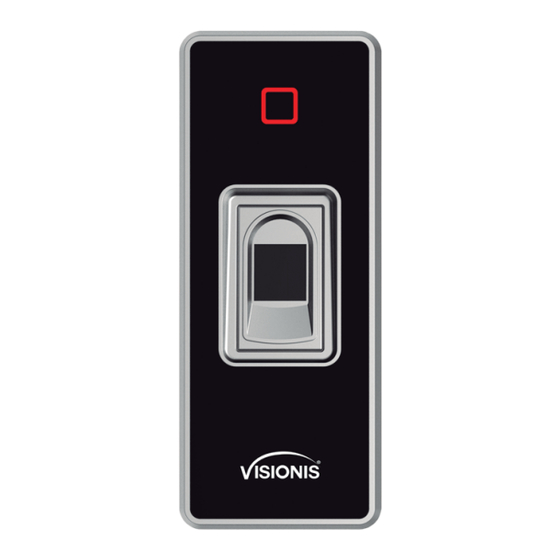
- Page 1 Fingerprint Reader for Access Control for Single Door User Manual VIS-3024 www.visionistech.com...
-
Page 2: Technical Specifications
1. Introduction The VIS-3024 is a new generation of multi-functional standalone access control. It adopts new ARM core 32-bit microprocessor design, which is powerful, stable and reliable. It contains reader mode and standalone access control mode etc.. It’s widely applied to different occasions, such as office, residential communities, villa etc.. -
Page 3: Installation
4. Installation - Remove the back cover from the keypad using the supplied special screw driver - Drill 2 holes on the wall for the self-tapping screws and hole for the cable - Put the supplied rubber bungs to into the two holes - Fix the back cover firmly on the wall with 2 self tapping screws - Thread the cable through the cable hole - Attach the keypad to the back cover. -
Page 4: Connection Diagram
6. Connection Diagram 6.1. Common Power Supply Note: The door contact and alarm function are optional 6.2. Special Power Supply Note: The door contact and alarm function are optional... - Page 5 6.3. Reader Mode 6.4. Connection for Lock and Button Fingerprint/ Card Reader Power Supply (COM) PURPLE WIRE FROM KEYPAD/READER Electromagnetic Lock (NC) ORANGE WIRE FROM KEYPAD/READER Exit Button (OPEN) YELLOW WIRE FROM KEYPAD/READER...
- Page 6 6.5. Connection for Lock, Button and PIR ORANGE WIRE Exit YELLOW Button WIRE Electromagnetic Lock Power Supply Power Supply 6.6. Connection for Lock, Button, and Receiver Fingerprint/ Card Reader ORANGE WIRE FROM KEYPAD/READER YELLOW WIRE FROM KEYPAD/READER Electromagnetic Lock PURPLE WIRE FROM KEYPAD/READER Receiver Exit...
-
Page 7: Sound And Light Indication
6.7. Connection to Access Control Panel 7. Sound and Light Indication Operation Status LED Indicator Buzzer Stand by Green Beep— Operation successful Beep-Beep-Beep Operation failed Beep-Beep Admin card enter programming Beep— Admin card exit programming Press digital key Beep Beep— Press * key Red indicator flash Read card under fingerprint + code mode... -
Page 8: Admin Menu
8. Admin Menu 8.1 Standalone Mode Settings Device Management Enter Default Menu Operation steps Description programming value New admin code # Change admin code 999999 new admin code # 10001# Read card Set add card or add / Press a fingerprint twice * fingerprint 10002# Read card Set delete card or delete... -
Page 9: Delete Users
Delete Users Enter Default Menu Operation steps Description programming value Read card / Input a Delete card users by reading fingerprint once... * card / Delete fingerprint Press * “…” means users by inputting fingerprint repeating Admin code # Press 8 or 10 digits card Delete card users by card (Default previous... - Page 10 Advanced Settings Enter Default Menu Operation steps Description programming value The external alarm and built-in Press * Admin buzzer will work if wrong code # operations are over 5 times. (Default admin The device will be locked out code is for 10 min if wrong operations "999999") are over 5 times.
-
Page 11: Other Operation
9. Admin Card / Admin Code Operation 9.1 Add Users Read admin add card / Input admin add fingerprint , Read the 1 user card / Input the first fingerprint twice Read the 2 user card / Input the 2 fingerprint twice …,Read admin add card / Input admin add fingerprint Note: The admin add card / admin add fingerprint is used for adding card / fingerprint...
Need help?
Do you have a question about the VIS-3024 and is the answer not in the manual?
Questions and answers