
Related Manuals for Visionis VIS-3003


Summary of Contents for Visionis VIS-3003
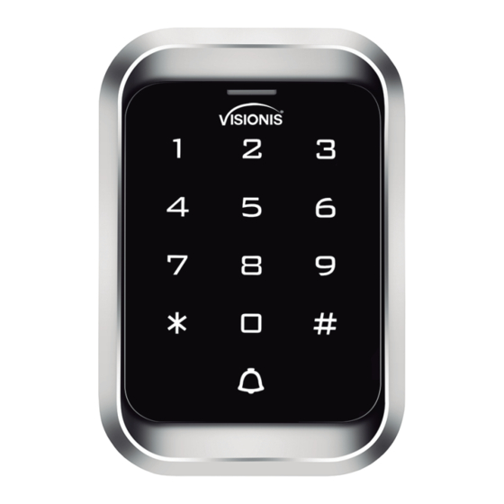
- Page 1 Standalone Access Control for Single Door VIS-3000 VIS-3003 User Manual VIS-3000 VIS-3003 www.visionistech.com...
-
Page 2: Specification
1. Description The device is a standalone as well as a Wiegand access control keypad and proximity card reader which supports EM, HID,a n d M i fa r e c a r d t y p e s ,i t ’ s one o f t h e most advanced standalone access control .Its build-in USA Atmel microprocessor,with strong anti-interference ability, high security and reliability, powerful function and convenient operation.It is widely used in high-end buildings,... -
Page 3: Sound And Light Indication
5. Wiring Marks Color Description BELL_A Pink Doorbell button BELL_B Pink Doorbell button Green Wiegand output D0 White Wiegand output D1 +12V Positive pole of power supply Black Negative pole of power supply OPEN Yellow Exit button D_IN Brown Door contact ALARM Gray Alarm Output... -
Page 4: Quick Programming Guide
7. Quick Programming Guide 7.1 Administrator Setting Stand Master Menu Setting Remarks Functions Code Orange Flash New master code# Factory Change the master Repeat new master default: code code # 999999 Read Manager Add Set Manager Add Card Card Master code# Read Manager Set Manager Delete... -
Page 5: User Setting
7.3 User Setting Stand Master Menu Setting Remarks Functions Code Orange Flash Read card # ID number # read Users can be card# added continuously To add card users without exiting Card number # programming mode ID number # card number # ID number # To add PIN users... - Page 6 7.4 User Optional Setting Stand Master Menu Setting Remarks Functions Code Orange Flash Buzzer will be in silence except enter the programming mode Buzzer will sound when press Default 1 the key Master Disable keypad backlight code# (Code Enable keypad backlight length: Default 2 Automatic mode...
- Page 7 8.1 Change the master code Press 00 new code # repeat new master code # Note: Master Code length: 6~8 digits. 8.2 Set Manager Card Set manager add card Press 01 read manager add card Set manager delete card Press 02 read manager delete card Note: When add the new manager card, the new one will automatically cover the old card, only one manager card for one device.
- Page 8 Note: 1.Card number must be 8 or 10 digits, if the card number is less than 8 or 10 digits, input 0 before the card number. 2. Automatically increases, the user ID will be generated by the machine automatically, the range is 1 ~ 2000, and automatically search from 1 to 2000. 8.7.4 Use ID number and card number to add user Press 11 ID number # 8-digits card number # ...
- Page 9 Press 14 0~99 # Note: 0~99 is to set the door delay time 0-99 seconds, factory default is 5 seconds. 8.11 Set Relay mode Relay setting -pulse mode Press 15 0 # Every time a valid card/tag read or PIN input, the relay will operate, for the pre-set relay pulse time.
-
Page 10: Setting Alarm Time
8.16 Setting keypad transmission format Press 33 0~2 # (Unable to initialize) Note: Keypad transmission format is 0 1 2, factory default is 0. 8.17 Setting alarm time Press 34 1~3 # (Unable to initialize) Note: 1. factory default is 1 minute. 8.18 Setting safe mode 8.18.1 Normal mode (factory default) Press 35 0 #... -
Page 11: User Operation
Flash LED light (factory default setting) Press 43 1 # Manager card operation 8.20 Add user Read Manager Add Card, read user cards continuously, read Manager Add card again. 8.21 Delete user Read Manager Delete Card, read user cards continuously, read Manager Delete card again. 9. -
Page 12: Remove Alarm
10.4 Remove alarm Read valid user card, manager card or input master code, then alarm will be removed. If no any operation, alarm will be removed automatically. 11. Connection Diagram 11.1 NO/NC Locks BELL_A P ink Normally Open BELL_B P ink 1 2 V +12V Door Strike... - Page 13 11.2 Connection with Accessories: Doorbell and Exit button Keypad/Reader Power Supply (COM) PURPLE WIRE FROM KEYPAD/READER Electromagnetic Lock PINK WIRE (NC) (BELL B) ORANGE WIRE FROM KEYPAD/ FROM KEYPAD/READER READER Exit Button (OPEN) YELLOW WIRE FROM KEYPAD/READER 11.3 Connection with Accessories: Doorbell, Exit button, and Wireless Receiver PINK WIRE FROM GREEN WIRE...
- Page 14 11.4 Connection with Accessories: Doorbell, Exit button, and PIR PINK WIRE FROM GREEN WIRE FROM KEYPAD/READER (BELL B) DOOR BELL PINK WIRE FROM KEYPAD/READER (BELL A) YELLOW WIRE ORANGE WIRE Keypad/Reader Exit YELLOW Button WIRE Electromagnetic Lock Power Supply Door Bell Power Supply 11.5 Connection with Access Control Panel BELL_A...
-
Page 15: Reset To Factory Default
12. Reset to Factory Default a. Power off. b. Press and hold # key, then power on. c. Release # key until hearing short beeps twice. When hearing long beep once, the device is in normal working state and reset to factory default setting, but the user data will not be deleted.
Need help?
Do you have a question about the VIS-3003 and is the answer not in the manual?
Questions and answers