Advertisement
Quick Links
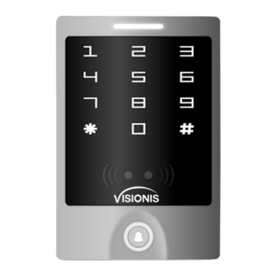
VIS-3000
Standalone Access Control Key/Reader
User Manual
Under Setting
Orange
Manager Card Reading
Orange
2 Short Ring
Manager Card Exit
White
Long Ring
Alarm
Quick Shine in Red
Alarm
Ring-back Tone
Ding-Dong
9. Master Setting
Logo LED Light indication
Remarks
Functions
White logo
Red logo LED flash
Factory default :
To enter the
programming mode
*
6-8 digits Master code #
888888
Enter Master Operation Mode. It will return to normal mode if there is no right Master PIN input in 5
seconds. After input of right master PIN, it will also return to normal mode if there is no valid operation
in 30 seconds. Press "#" to confirm the input number, return to previous menu by press "*", the logo
light will indicate the operation mode.
Note that to undertake the following programming, the master user must be logged in
9.1 Basic Operation
9.2 Advanced operation:
Advanced Application
Red
Orange
Orange
Functions
Remarks
Flash
Flash
1. Introduction, Features and Specifications
1.1 Introduction
The Vsionis VIS-3000 Stand alone access control Reader/Keypad Card or Key tag reading and keypad
operation functions, lock, alarm, ring bell, exit button and the Alarm magnetic contact switch on the
door.
The access host supports 125KHz EM, HID cards.
It controls 1 door, and supports up to 2000 users in total, each user have one card and one PIN.
The access control unit supports 1 master code, one manager add card, one manager delete card,
1 anti-duress card and 1 anti-duress PIN, providing users with easy operation and safe guarantee.
1.2 Features
> Aluminum alloy case, waterproof, weather Proof, confirms to IP65 Standard touch panel
> Built-in 125KHz (EM, HID card) and 13.56MHz(IC, CPU card, ISO14443A) reader touch panel
> The back light can be set to Normal ON, Normal OFF or Auto.
> With door bell function, build-in or external door bell optional.
> Multi-function, operating as slave reader, single door, anti-pass back function, etc, suitable for
Different type of Installations.
1.3 Specifications:
Operating voltage range: DC12-24V
Idle input current: ≤35mA
Max proximity card read range: EM&HID card: 3-6cm IC&CPU card: 2-6cm
Frequency: 125KHz and 13.56MHz
Card transmit format: Wiegand 26-37
Keypad transmit format: 4-6 digits key press to output card number format, 4 bits or 8 bits data.
Access control unit dimensions (Height×Width×Depth) 125×83×21.7mm Or 4.92x3.27x0.85
Inches
Operating temperature range: -40~60° C or -40°F ~140°F (EM&HID card), -20~60° C or
-4°F ~140°F IC or CPU
2. Installation and Wiring Diagram
1
2
3
Drill Holes
Fix the Bracket and
Fix Safe Screws
Install the Access Host
For concrete wall, drill the hole in 6mm diameter
Sticker Size : 78 X 121mm
Product Bracket Size : 72.8 X 115.9mm
Diameter
:
6mm (Rubber Bungs )
Diameter
:
2mm
Diameter
:
30mm
60.60 mm
Safe Screws
Pay attention to the sequence during installation
VIS-3000 Installation
1
Read card
Set add card
To add card user
2
Read card
Set delete card
To delete card user
3
Read card
To set duress users
To set duress user
8 digits duress PIN,#
4
To set duress PIN
To set duress PIN
0, #
Automatic mode Factory default
(
)
5
Relay setting
6
1, #
Set Zone 1as Auto-lock switch①
To set open door by
1-10, #
Factory default setting :1
6
multi cards②
User ID number # card
The card number must be consecutive
To add a series cards
7
number # card quantity #
Card quantity is between 1-2000
users. ③
9
1
Administrator open door 1
Exit automatic④
System Setting
0
1-15, #
Factory default setting: 0
To set facility code
Wiegand reader mode
0, #
1, #
Standalone for single door Factory default
(
)
To set working mode
1
5, #
Anti-passback for single door
2
26-37, #
( Factory default setting: 26 )
To set Wiegand format
0, #
4-6 digis key press sends card number
7
Each key press sends 4 bit output data
To set keypad
3
1, #
( Factory default )
transmission format
2, #
Each key press sends 8 bit output data
0, #
Close Alarm⑤
4
Alarm time is 0-3 minutes for option
To set Alarm
1-3, #
( Factory default 1 minute )
Opeional Setting
0, #
Indicator light OFF⑥
1
To set logo LED light
1, #
Indicator light ON ( Factory default )
0, #
Disable buzzer ⑦
2
1, #
Enable buzzer ( Factory default )
0, #
Disable keypad backlight
1, #
Enable keypad backlight ( Factory default )
3
2, #
Auto mode⑧
8
0, #
Disable anti tamper alarm ( Factory default )
4
1, #
Enable anti tamper alarm
0, #
No keypad lockout or alarm (Factory default)
5
In 10 minutes, if there's 10 times⑨invalid
1, #
card or wrong password, the device will lock
on for 10 minutes.
In 10 minutes, if there's 10 times invalid card
2, #
or wrong password, the device will alarm.
Remark:
① Every time a valid card/tag read or PIN input in in Toggle mode, the relay changes state, which will not turn
back until read card/tag or input PIN again.
②The door will open only when read the valid card quantity up to the quantity set. It is only for Card Only mode.
③ The card number must be consecutive, Card quantity is between 1-2000.
④ After unlocking, enter the normal working state.
⑤ After closed the alarm, anti tamper, anti-duress and door magnetic alarm are invalid.
⑥ Refers to static state, normal indication according to operation.
⑦ Enter the administrator password correctly, the buzzer alarm in the normal phonation.
⑧ Each key press or read card, keypad backlight will light 30S delay after the close, in close state , the first key
is just to start the keyboard light, no any function.
⑨ 10 times consecutive errors including: enter an invalid master code, user password, or anti-duress or invalid
card.
Wiring Diagram
Standalone Access Control
Light
Pink
Red
Black
Green
White
Brown Yellow
blue
Purple Orange Gray
green
Door
Bell
Green
White
Reader
DC 12V
Power
Red
Black
VIS-3000 Single door(DC power supply )
Standalone Access Control
Access Control
Power Supply
PUSH
Factory
Reader
50mS
default 0(50mS)
Door
Bell
VIS-3000 Single door (Special access control power supply )
Principle of Door Bell Connector
BELL_A
Each press of door bell button, contact of relay in BELL_A and BELL_B will
BELL_B
close contact for 200mS then release.
Principle of Alarm Connector
+12V
+12V
ALARM-
The field-effect tube will be conducted when alarm is activated; It will be not
conducted when alarm is removed
+12V
+12V
Principle of Electronic Lock
NO
The relay will close contact to unlock the lock and will release after unlocking
NC
COM: common, relay contact
NC: normal close, normally keep closed to COM
COM
NO: normal open, normally keep opened to COM
GND
10. Various Working Modes Application
The device has 3 working modes:
1. Wiegand Reader
2. Standalone for single door (Factory default setting)
3. Anti-pass back for single door
Through Wiegand data lines , can make the device and external card reader are connected together, to realize
of various functions.
Card number and PIN etc information will store in the device.
The external reader only read card or as a device for input PIN, you can connect with a numbers of readers , but
function all same.
External Reader
Access
Access
(Inside Door)
Host
Host
(Outside Door)
(Outside Door)
Standalone for single door
Anti-pass back for single door
10.1 Wiegand Reader Mode
Standalone Access Control ( Reader Mode)
Light
Pink
Red
Black
Green
White
Brown Yellow
blue
Purple Orange Gray
green
+12V
CND
D0
D1
LED
BZ
Common Access Control
Door
Bell
VIS-3000 Reader Wiring Dragram
In this mode, the access host works as reader, it can be done below settings.
Administrator Setting
White
Red flash
Functions
Remarks
6-8 digits Master code #
Factory default :888888
*
Enter programming mode
Reader Setting
Red
Orange
Orange
Functions
Remarks
Flash
Flash
6~8 digits new master
code # Repeat 6~8
Change the master
0
Factory default : 888888
digits new master code
code
#
NC
LOCK B
NC
LOCK A
COM
+
+12V
COM
+12V
+
NO
GND
1N4004
NO
GND
1N4004
Wiring of electronic lock
Connect COM and GND, connect two ends of electronic lock with +12Vand NO or NC, complete
the circuit.
Type A electronic lock: Fail Secure lock (Unlock when power on), such as Electronic Controlling Lock,
smart lock.etc.
Type B electronic lock: Fail Safe lock (Unlock when power off), such as Electromagnetic Lock,
Electronic Bolt Lock, etc.
1N4004 Diode: prevent high voltage to two ends of the electronic lock while the contact of relay
disconnect .Without diode, there will be high voltage pulse interference to circuits and the life time of
the relay will be greatly reduced.
3 . Manager Cards Operation
3.1 Add user card(s)(In dual door mode, users can be only added to zone 1)
Read manager add card Read Usercard Read manager add card
Cards can be added continuously.
3.2 Delete user card(s)
R
ead manager delete card Read User card Read manager delete card
Cards can be deleted continuously.
4. User Operation
4.1 To unlock the lock by one card: Read valid card once, the lock will be unlocked.
4.2 To unlock the lock for card and PIN users
Read valid card once Input 4-6 digits PIN # , the lock will be unlocked.
4.3 To unlock the lock for card or PIN users
Read valid card Or Input 4-6 digits PIN # , the lock will be unlocked
4.4 To unlock the lock for multi cards: Read 2-10pcs valid cards (time interval can not exceed 5s), the
lock will be unlocked.
Precondition: Set the door entry by card only, and set "2-10"for opening the door by multi cards
4.5 Toggle Mode
In normal mode, Every time a valid card/tag read or PIN input, the replay will operate, for the pre-set
replay pulse time.
Every time a valid card/tag read or PIN input in Toggle mode, the relay changes state, which will not
turn back until read card/tag or input PIN again.
4.6 To change the PIN of a PIN user
Read card Input old PIN # Input new PIN # Input new PIN #
*
Or
User ID number Input old PIN # Input new PIN # Input new PIN #
*
Remark:
For users without card, must get ID number and initial PIN from the master. For Zone 1, the first digit of
PIN must be "1", for Zone 2, the first digit of PIN must be "2" For the card users with PIN "1234", must
use Reading card to change the PIN for the first time.
03
0-15, #
Factory default setting: 0
To set facility code
0
26-37, #
Factory default setting:26
To set Wiegand format
2
0, #
4-6 digis key press sends card number
Each key press sends 4 bit output data
To set keypad
3
1, #
(Factory default setting)
transmission format
2, #
Each key press sends 8 bit output data
7
0, #
Close Alarm
4
To set Alarm
1-3, #
Alam time is 0-3 minutes for option
0, #
No door bell function
Built-in door bell- ON (Factory default
1, #
To set door bell
setting)
5
function
2, #
External door bell-ON
3, #
Built-in & external door bell - ON
0, #
Disable
1
To set logo LED light
1, #
Enable(Factory default setting)
OFF-The device will be in silence
0, #
except enter the programming mode
To set keypad tone
2
ON or OFF
ON-The device will give the voice when
1, #
press the keys (Factory default setting)
0, #
Disable keypad backlight
To set keypad
8
Enable keypad backlight (Factory
backlight
1, #
default setting)
3
Automatic mode
To set keypad
2, #
Normally it is off(sleeping mode) but
backlight
wake up with human approach
Disable anti tamper alarm ( Factory
0, #
To set anti tamper
default setting )
4
alarm
1, #
Enable anti tamper alarm
When LED level is low, logo light will turn into Green, after 30 seconds or LED level rising, Logo light will back to
normal.
When BZ level is low, the Buzzer will beep, after 30 seconds or BZ level rising, the Buzzer will back to normal.
When the access host worked as reader, both card number and keypad transmits in Wiegand format, the output
data are shown by the Low Level of D0 & D1 cable:
D0: Low level means 0, green cable
D1: Low Level means 1, white cable
The Pulse Width of Low level is 40uS, Bit period is 2mS.
The digit of Car number can be set to 26~27Bit, should be matched with the controller. (Factory default is 26Bit)
Wiegand 26 card reader, HID card can output Wiegand 26~37 automatically, other cards are output Wiegand 26
compulsively.
Wiegand 27~37 card reader, all cards are forced output Wiegand 27~37.
Keypad transmission can be set in the following 3 modes
Model 0: The Reader will transmit the PIN data when it receives the last key (#) press after PIN code
Format: Decimal card number with 10-digit , Facility Code(1st ~ 4th digit)+ PIN Code (5th ~ 10th digit)
(Facility code is any digits between 0~15, PIN code is 4~6 digits)
Example: Facility code:15
PIN code: 2999
Press 2999 #, then output format will be: 0015002999
PIN code: 999999
Press 999999#, then output format will be 0015999999
4.7 Door Bell
Press the door bell button on the access control unit, the buzzer will sound ring back tone, at the same
time, the I box's built-in door bell or the outer door bell will ring.
Remark: When the work mode is set in Auto Mode (Factory Default Mode), there will be no ring
back tone without the I Box.
5. Alarm
5.1 Anti Tamper Alarm
When the access control unit is disassembled illegally, the access control unit's buzzer and the external
alarm will operate.
5.2 Door Status Switch
When connect with door status switch, if the door is opened illegal, the access control unit's buzzer and
the external alarm will operate.
5.3 Anti-duress alarm
When read zone 1 duress card / input 8digits duress PIN OR zone 2 duress card / input 8digits duress PIN,
then press #, the corresponding lock will open, at the same time, the external alarm will operate, but the
access control unit's buzzer will not operate.
5.4 To remove the alarm
Read valid card or input master code can remove the alarm. If there is no operation, the alarm will remove
automatically after 1 minute.
6. Keypad lockout or alarm
To prevent consecutive enter of an invalid master code, user password, or anti-duress or invalid card,
this function will be activated after 10 times consecutive errors input. There are 3 mode available:
No keypad lockout or alarm, keypad locked for 10 minutes, alarm for 1-3 minutes.
7. To Reset to Factory Default
Keypad access control, power off, keep pressing * and power on, the logo will turn in orange after 1
second, release it until hearing two shot beep , then hearing a long beep, enter normal mode, reset to
factory default setting is successfully.
Touch panel access control (VIS-3000) ,power off, power on, the logo will turn in orange after 1 second,
press * within 1 second, release it until hearing two shot beep, then hearing a long beep, enter
normal mode, reset to factory default setting is successfully.
Remark: Reset to factory default, the users' information is still retained.
8. Sound and Light Indication
Operation Status
Logo Color
Buzzer
Standby
White
Press Key
Short Ring
Long Ring
Read Card
Green
Unlock the lock
Long Ring
Green
Operation Successful
Green
Long Ring
Operation Failed
3 Short Ring
PIN Inputting
Slow Flash Red
Card & PIN Reading
Slow Flash Red
Multi Card Reading
Slow Flash Red
1 Menu
st
Slow Flash Red
nd
2 Menu
Slow Flash Orange
Model1: 4-Bit
The output data is provided in following format after every key is pressed:
1(0001),2(0010),3(0011)
4(0100),5(0101),6(0110)
7(0111),8(1000),9(1001)
*(1010),0(0000),#(1011)
Model 2: 8-Bit
The output data is transmitted in following format after every key is pressed:
1(11100001),2(11010010),3(11000011)
4(10110100),5(10100101),6(10010110)
7(10000111),8(01111000),9(01101001)
*(01011010),0(11110000),#(01001011)
10.2 Standalone for Single door
In this mode, the access host uses can open the door by valid card or PIN, it supports connecting external card
reader for exiting door.
When input duress PIN/Card, the door will open, at the same time, the external alarm operates
10.3 Anti-passback for Single Door
> In this mode, access host install outside is for entering door, external reader inside for exiting door, they build
up a single door anti-passback system, access host is the anti-passback master unit.
> Read valid card or input PIN on access host, door will open; read valid card or input PIN on external reader,
door will open.
> When input duress PIN/Card, the door will open, at the same time, the external alarm operates
> When input duress PIN/Card on external reader, the door will open, at the same time, the external alarm
operates.
> Open type forced Card Only, the user PIN is invalid.
> The users can only enter door when read valid card on access host, and exit from the inside external reader,
If without the entering record from access host, the users can not exit from the inside reader, also the users
can't enter in twice without the first exit record.
11. Simple Troubleshooting
Fault Phenomenon
Fault Cause
Reason & Solution
1. Card problem
1. Please use original made card
Reading distance
2. Switch power supply
2. Wiring power supply and access host shell to ground
is too close
interferences card reading
wire
1. In mode of two Doors 1,the 1st digit of PIN must be 1.
1. Wrong way of PIN setting
Two doors 2, the 1st digit of PIN must be 2.
Set user PIN failed
2. Setting PIN under card
2. User PIN cannot be 1234
reading mode
3. User PIN only can be 4~6 digits
Can't open door
1234 is the initial value, can't be used to open doors,
after inputting
Use 1234 as user's PIN
unless after resetting them to other 4~6 digits
user's PIN
Alarm under
Light leaking when install
Leaning on wall closely when install access host
normal situation
access host
No reaction when
not on standby status
Exit by pressing * until logo light turns to white
reading card
1. Set the keypad light to always On or automatic mode
Set keypad light mode
Keypad light off
2. Under automatic mode, keypad light will on when
improperly
people approaching
Cannot enter
Reset to Factory Default, default master code is 888888,
Administrator
Forget master code
need to reset conditions and specifications, but users'
setting mode
information is still retained
For other issues beyond above, welcome to contact our technicians for more details.
Advertisement


Need help?
Do you have a question about the VIS-3000 and is the answer not in the manual?
Questions and answers