Table of Contents
Advertisement
Quick Links
Advertisement
Table of Contents

Subscribe to Our Youtube Channel
Related Manuals for UEi KM940


Summary of Contents for UEi KM940
- Page 1 KM940 Hand-held Combustion Analyser...
-
Page 2: Table Of Contents
CONTENTS Page No: ANALYSER LAYOUT AND FEATURES............4-7 Instrument features and keypad................4 Instrument layout (Rear) ..................5 Standard Probe Configuration ................6 Analyser connections ..................7 SAFETY WARNING ....................8 FIRST TIME USE ......................8 NORMAL START UP SEQUENCE..............9-15 Every Time You Use The Analyser ..............9 Automatic Calibration ..................9 Main Display Parameters ..................11 4.3.1... - Page 3 MAINTENANCE .......................26 Emptying and Cleaning the in-line water trap ..........26 Changing the particle filter................26 PROBLEM SOLVING ....................27 ANNUAL RE-CALIBRATION .................27 PRODUCT SPECIFICATION ................28-29 APPENDICES: MAIN DISPLAY PARAMETERS ................30 COMBUSTION EFFICIENCY CALCULATION..........32-33 CALCULATION OF FUEL DATA................34 ELECTROMAGNETIC COMPATABILITY STATEMENT ........35 - 3 -...
-
Page 4: Analyser Layout And Features
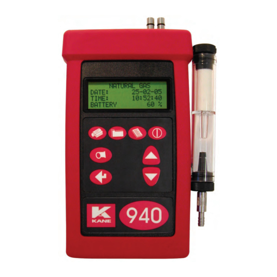
ANALYSER LAYOUT AND FEATURES Instrument Features and Keypad Infra-red emitter Pressure Inlet RS232 (8 pin din) Inlet Port (side) Charger socket Menu Store Print On/Off Pump Down Enter Keypad Flue Temperature Connector (underside) ON/OFF Scrolls up through options ie Fuel MENU DOWN Allows access to all menu functions... -
Page 5: Instrument Layout (Rear)
1.2 Instrument Layout (Rear) Options Label Charger Socket SENSORS FITTED Exhaust Port NOTE! - Cover Does Not Remove Serial Number *NOTE! Do not cover exhaust port as this will severely affect analyser operation - 5 -... -
Page 6: Standard Probe Configuration
1.3 Standard Probe Configuration - 6 -... -
Page 7: Analyser Connections
1.4 Analyser Connections Gas Connection to Instrument Particle Filter In-line Water Trap Neoprene Hose Flue Temperature Connector - 7 -... -
Page 8: Safety Warning
SAFETY WARNING This analyser extracts combustion gases that may be toxic in relatively low concentrations. These gases are exhausted from the side of the instrument. This instrument must only be used in well ventilated locations. It must only be used by trained and competent persons after due consideration of all the potential hazards. -
Page 9: Normal Start Up Sequence
NORMAL START UP SEQUENCE Every Time You Use The Analyser BEFORE SWITCH-ON CHECK THAT: the particle filter is not dirty the water trap and probe line are empty of water all hose connections, etc, are properly made the probe is sampling CLEAN AMBIENT air the water trap is correctly fitted and the instrument upright the flue temperature is connected Switch ON the instrument by pressing... - Page 10 Once the time has reached zero an audible beep will be heard and will show the selected fuel on the following display:- NATURAL GAS ∗ ∗ PRESS -MENU- KEY Press This zeros the toxic sensor and sets Oxygen to 20.9%. The next screen is the MAIN DISPLAY of the analyser:- NETT .
-
Page 11: Main Display Parameters
Main Displays The main display can be changed to show either 4 or 8 parameters at one time. Two options are available when 4 parameters are selected. • 4 Page Mode displays 4 lines of data in set format, each page is predefined. •... -
Page 12: Line Scroll Mode
4.3.2 Line Scroll Mode Line scroll mode allows you to customise the display. Use the keys to change the bottom line of the display. Once the correct line is displayed press to confirm and move the line up. Select the next parameter and repeat until all lines display the desired parameters. -
Page 13: Sampling The Flue Gas
Sampling the Flue Gas Once the automatic calibration procedure has been completed and the specific fuel has been selected (See SELECT menu) the probe can be inserted into the desired sampling point. It is recommended that the sampling point be located at least two flue diameters downstream of any bend and that the probe tip is in the centre of the flue. -
Page 14: Regular Checks During Sampling
Regular Checks During Sampling Care must be taken at all times not to exceed the analysers operating specifications, in particular ensure the following :- • Do not exceed the maximum temperature of the flue probe. • The analyser internal temperature does not exceed normal operating range, typically 0- 40°C. -
Page 15: Electromagnetic Compatibility
Electromagnetic Compatibility The European Council Directive 89/336/EEC requires that electronic equipment does not generate electromagnetic disturbances that exceed defined levels and has an adequate level of immunity to enable it to be operated as intended. The specific standards applicable to this product are detailed in the appendices. -
Page 16: Moving Through The Menus
MOVING THROUGH THE MENUS Basic Operation NETT ..From the MAIN DISPLAY . . . 20.9 ppm . . . 0000 EFF (G) % . . . MAIN MENU Press SELECT 3. DISPLAY to access the MAIN MENU 2. -
Page 17: Menu Options And Settings
Menu Options and Settings 5.2.1 Main Menu The MAIN MENU consists of 4 sub menus which are shown below and detailed on the following pages. MAIN MENU SELECT 3. DISPLAY 2. UNITS 4. SETUP All sub-menus are accessed using and exited using keys move the cursor within a menu and allow parameters to be changed. - Page 18 Calculation of fuel constants are detailed in the Appendix. Fuel constants will have to be calculated before a user fuel can be entered. To enter the user fuel select ‘User Fuel’ and Press USER FUEL 0.000 : 0.000 : 0.00 : 0.00 to select the correct value.
-
Page 19: Units Menu
Selecting YES and will display the following screen. RESET SENSORS O2 % : 20.9 CO & NO = 0 PRESS ENTER MENU TO ESCAPE After pressing the analyser will count down for 5 seconds and then return to the main display. WARNING : The sensors must only be reset if you are sure they have been sampling fresh air for at least 3 minutes. -
Page 20: Display Menu
5.2.4 Display Menu LIGHT : OFF MODE : 8-PAGE CONTRAST : DEFAULT Allows the configuration of the display to be changed. LIGHT : Choose from ON or OFF. MODE : Select 4 or 8 Page Mode or Line Scroll Mode as detailed in section 4.3 Main Displays. - Page 21 Once an alarm has been exceeded the display will flash every two minutes warning the user of an alarm state and display the gas concentration. A similar display will be shown during a RECHARGE BATTERY and PUMP OFF alarms. -- -- -- -- -- -- -- -- -- -- -- -- -- -- CO ALARM 1010 ppm -- -- -- -- -- -- -- -- -- -- -- -- -- --...
- Page 22 Allows two lines of 20 characters to be Header : programmed into the analyser. The header appears on the top of the standard printout. This can be used to print your company name and/or phone number. Name/Phone Kane International (44)-1707-375550 ‘LEFT’...
-
Page 23: Printing Information
PRINTING INFORMATION Supplied as accessories for the KANE940 are an infra-red thermal printer or a dot matrix serial printer. Read the manual supplied with each printer prior to operation. Connections to the KANE940 are detailed below : • Infra-red thermal printer - this does not require a cable to transmit the data but uses an infra-red (IR) link similar to a TV remote control. -
Page 24: Storing And Retrieving Data
STORING AND RETRIEVING DATA The KANE940 can store up to 100 combustion tests. Once stored, the data can be viewed on the display or downloaded to a PC or printer. Storing a ‘Live’ Test While performing a test and viewing the data on the MAIN display access the STORE menu as follows :- Press STORE MENU... -
Page 25: Deleting Data
To print the data press . In the screen shown above locations 1 to 10 will be printed. During printing the following will be shown. PRINT TESTS 1 to 10 PRINTING TEST 1 NOTE While the display above is shown (i.e. the instrument is printing a test) the keypad is disabled. -
Page 26: Maintenance
MAINTENANCE Emptying and Cleaning the In-line Water Trap The in-line water trap should be checked and emptied on a regular basis. Water vapour will condense and gather in the probe line. This may move suddenly to the trap when the probe is moved. -
Page 27: Problem Solving
PROBLEM SOLVING The following is a list of problems that may occur on the instrument through its operating life. If the cause of the fault is not easy to identify then we advise you contact Kane International Service Department or an International Distributor for expert advice. Fault symptom Causes •... -
Page 28: Product Specification
PRODUCT SPECIFICATION Parameter Resolution Accuracy Range Temp Measurement Flue Temperature with 1.0ºC/F +2.0ºC +0.3% reading 0-600ºC probe 32-1112ºF Inlet Temperature 0.1ºC/F +1ºC +0.3% reading 0-50ºC/32-122ºF Pressure 0.01 mbar +2% of full scale +150mbar to -150mbar Gas Measurement Oxygen 0.1% +0.2% 0-21% Carbon Monoxide 1ppm... - Page 29 Dimensions Weight Handset 220mm x 55mm x120mm L 420mm x Dia 8mm with stainless steel shaft, type K thermocouple Probe and 3m hose C to 45 C/ 10% to 90% RH non condensing Ambient operating range Input 110Vac / 220Vac nominal Power supply (battery charger) Output: 12Vac off load...
-
Page 30: Appendices
APPENDICES A - Main Display Parameters The parameters and their meanings are detailed as follows : - DATE : Analyser date. See Set-Up menu section 5.2.5 to change. TIME : Analyser time. Use Set-Up menu section 5.2.5 to change. BATTERY : Displays the battery level from 0-100%. - Page 31 (Ta) temperature calculation if an INLET probe is not fitted. CO/CO2 R : The CO/CO 2 ratio, is the ratio of measured CO divided by calculated CO 2 . It gives an indication of the following :- • How good a gas sample the instrument is reading. •...
-
Page 32: Combustion Efficiency Calculation
COMBUSTION EFFICIENCY CALCULATION The efficiency calculation is based upon British Standard BS845. This identifies three sources of loss associated with fuel burning: Losses due to flue gasses: Dry Flue gas loss, Moisture and hydrogen Sensible heat of water vapour Unburned gas Losses due to refuse: Combustible in ash Combustible in riddlings... - Page 33 Calculated data: Tnet = Net Temperature % CO content in flue gas % Dry Flue Gas losses % Wet losses % Unburned carbon loss % Efficiency Tnet = Flue Temperature - Inlet Temperature Dry flue gas loss % = 20.9 x K1 x (Tnet) / K2 x (20.9 - O Wet loss % = 9 x H O / Qgr x [2488 + 2.1Tf - 4.2 Ti]...
-
Page 34: Calculation Of Fuel Data
CALCULATION OF FUEL DATA For any fuel not specified by Kane International the net calorific value, gross calorific value and composition should be obtained from the fuel supplier. The following fuel data has been calculated with reference to the efficiency calculation. Example 1: Chemical composition: 8.35 MJ/kg... -
Page 35: Electromagnetic Compatability Statement
ELECTROMAGNETIC COMPATABILITY (CE) STATEMENT This product has been tested for compliance with the following generic standards: EN 61000-6-3 EN 61000-6-1 and is certified to be compliant Specification EC/EMC/KI/KANE940 details the specific test configuration, performance and conditions of use. Please Note: Batteries used in this instrument should be disposed of in accordance with current legislation and local guidelines.
Need help?
Do you have a question about the KM940 and is the answer not in the manual?
Questions and answers