Table of Contents
Advertisement
Quick Links
Advertisement
Table of Contents

Related Manuals for Idis DC-B1803


Summary of Contents for Idis DC-B1803
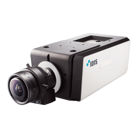
- Page 1 DC-B Series Installation Manual DC-B1803 Powered by...
- Page 2 Before reading this manual This is a basic installation manual for use of an IDIS network camera. Users who are using this product for the first time, as well as users with experience using comparable products, must read this manual carefully before use and heed to the warnings and precautions contained herein while using the product.
- Page 3 Before reading this manual Safety Precautions WARNING RISK OF ELECTRIC SHOCK DO NOT OPEN WARNING: TO REDUCE THE RISK OF ELECTRIC SHOCK, DO NOT REMOVE COVER (OR BACK). NO USER-SERVICEABLE PARTS INSIDE. REFER SERVICING TO QUALIFIED SERVICE PERSONNEL. Important Safeguards 1.
- Page 4 IDIS Co., Ltd. reserves all rights concerning this manual. Use or duplication of this manual in part or whole without the prior consent of IDIS Co., Ltd. is strictly prohibited. Contents of this manual are subject to change without prior notice for reasons such as functionality enhancements.
-
Page 5: Table Of Contents
Table of Contents Part 1 – Introduction ......... 6 Product Features . -
Page 6: Part 1 - Introduction
You • Easy network access via UPnP (Universal Plug and can use the IDIS Discovery program to change network Play) function and embedded mDNS (Multicast DNS) camera settings or the IDIS Solution Suite Compact protocol program to manage multiple network cameras. -
Page 7: Accessories
Part 1 – Introduction Accessories Upon purchasing the product, check inside the box to make sure all the following accessories are included. External appearances and colors of the accessories may vary depending on the model. Network Camera C-Mount Ring Installation Parts Protective Cover (attaches to camera) Ferrite Core Open Source Guide... -
Page 8: Overview
Part 1 – Introduction Overview Side Product color and design may vary depending on the model. Front Protective Cover C-Mount Ring Back Focus Adjustment Ring Mount Bracket SD Memory Card Slot Built-in Microphone • Protective Cover If the lens is not attached to the camera, use the Image Sensor protective cover to protect the image sensor. -
Page 9: Top
Part 1 – Introduction • Mount Bracket This bracket can be installed on either top or bottom of the camera. Use 1/4–20 UNC (20-thread), 2.5mm +/- 0.2mm (ISO standard) or 0.197 (ASA standard) screws to attach the mount. • SD Memory Card Slot Pull on the connection cover and then insert a microSD memory card into the slot. - Page 10 Part 1 – Introduction • Alarm I/O • Factory Reset Switch - Out: It is the BJT (Bipolar Junction Transistor) - Restores the camera's default factory settings. For open collector output. If the voltage and current more information, refer to the Factory Reset. exceed the specification limit (Max load: 50mA, When inserting an , audio in/out, or RS485 connector, Max Voltage: 30VDC), the product could be...
- Page 11 It's also possible to do a factory reset by pressing and releasing the reset switch while the camera is turned on or using the IDIS Discovery program from a remote location. A factory reset will reboot the system. For more...
-
Page 12: Back
For more information on network connection setup, refer to the IDIS Discovery operation manual. • Network LED Indicates the network connection status. For more Auto Iris Lens Connector information, refer to the LED Status Indications. -
Page 13: Installation
Part 1 – Introduction Power Connector • When switching over from 12 VDC to PoE as the power source, the system will be rebooted once the power adapter is disconnected. • Ground the power port's frame ground terminal before use. •... -
Page 14: Manual Iris Lens
Part 1 – Introduction Manual Iris Lens Remove the protective cover from the camera. Turn the lens in clockwise direction, mount it on to the camera, and connect the auto iris jack to the Remove the protective cover from the camera. auto iris lens connector. -
Page 15: C-Mount Lens
Part 1 – Introduction C-Mount Lens Dimensions Front 75.6 mm (2.98") Remove the protective cover from the camera. Turn the mount ring in clockwise direction and mount the ring on to the camera. Turn the C-mount lens in clockwise direction and Side mount it on to the C-mount ring. -
Page 16: Part 2 - Camera Connection
Part 2 - Camera Connection Use the camera by connecting to DirectIP™ NVR or non DirectIP™ NVR, VMS such as IDIS Solution Suite Compact. With DirectIP™ NVR-based Layout Audio In Audio Out Power Alarm Out Sensor In Network Camera Monitor Out... -
Page 17: With Non Directip™ Nvr-Based Layout
Ideal for using the camera over the network from a remote location. The contents in the camera operation manual are only for users using the camera with non DirectIP™ NVR connection or VMS connection such as IDIS Solution Suite Compact. -
Page 18: Part 3 - Appendix
ID and password as a safety precaution. camera. Unable to launch IDIS Web. If the IDIS Web login screen is not loading, check which version of Microsoft Internet Explorer you are using. IDIS Web may not launch properly on versions 8.0 or below. -
Page 19: Specifications
Part 3 - Appendix Specifications These product specifications may change without prior notice. Camera Image Sensor 1/2.5" CMOS Lens (optional) P-Iris, Manual iris, DC type auto iris (megapixel recommended) Lens Mount CS/C-Mount Minimum Subject Lux COLOR : 0.475 Lux @ F 1.8 (30 IRE) B&W : 0.0093 Lux@F 1.8 (30IRE) Scanning Method Progressive scan... - Page 20 Part 3 - Appendix Audio Compression Algorithm G.726 (8KHz), G.711 μ – Law (8KHz), ADPCM (16KHz) Video Out** 1 composite, 1 Vp-p Audio In 1 line in or 1 built-in microphone Audio Out 1 Line Out Alarm In 1 TTL, NC/NO programmable, 4.3V (NC) or 0.3V (NO) threshold, 5 VDC Alarm Out 1 TTL open collector, Max load:50mA, Max voltage:30VDC Network Connection...
- Page 22 IDIS Co., Ltd. For more information, please visit at www.idisglobal.com...
Need help?
Do you have a question about the DC-B1803 and is the answer not in the manual?
Questions and answers