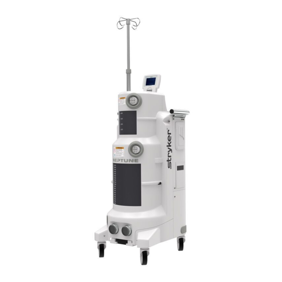
Stryker Neptune 2 Service And Installation Manual
Waste management system
Hide thumbs
Also See for Neptune 2:
- Instructions for use manual (71 pages) ,
- Installation, operation and maintenance manual (24 pages) ,
- Instructions for use manual (14 pages)
Table of Contents
Advertisement
Quick Links
Advertisement
Table of Contents
Troubleshooting

Related Manuals for Stryker Neptune 2


Summary of Contents for Stryker Neptune 2
- Page 2 ® Neptune Waste Management System Service and Installation Manual REF 0702-002-620 120 V Rover – ULTRA REF 0702-001-000 120 V Docking Station REF 0702-014-000...
- Page 4 Waste Management System Service and Installation Manual REF 0702-002-620 120 V Rover – ULTRA REF 0702-001-000 120 V Docking Station REF 0702-014-000 ® ® Stryker and Neptune are trademarks and/or registered trademarks of the Stryker Corporation. 2008/06 0702-002-619 Rev-None www.stryker.com...
- Page 6 Chapter 1 – Operational Description Here you will find a brief overview of how the Neptune 2 Waste Management System works. Included topics are: • The components in each subsystem (i.e. vacuum subsystem, or fresh water subsystem) •...
- Page 7 Warning Indicators and Disassembly Procedure Example The following examples illustrate how the disassembly procedures are structured as well as the warning indicators used when performing maintenance in the field. The disassembly procedures apply to chapters 2, 3, and 4, although each chapter will cover the steps necessary to perform maintenance on a specific product.
- Page 8 For the most part the process starts with the covers and proceeds through removing each component, one at a time. The technician should ensure that the equipment is unplugged and turned off during disassembly!! Power should not be applied when removing components or subassemblies. Components are assembled in reverse order of assembly and therefore reassembly of the equipment is not covered.
- Page 9 Warning Indicators Certain steps in the disassembly process will require the technician to take special precaution. In this case the step, or sometimes even the whole procedure, will be preceded by a warning indicator. The message contains an indicator, a warning level, and the message.
- Page 10 Disassembly Step Each step in the removal process outlines the following: Component: The component name is always in bold. Part Number: The part number for the component being removed. Reference Designator: A visual reference to the component to remove. Required Tool: Lists the tool needed to perform the listed action Sometimes a component may be listed in a procedure without a part number.
- Page 11 Disassembly Diagram The diagram provides the technician with a visual reference of the components to be removed. The reference designators shown help the technician to correspond each part in the diagram to the one listed in the disassembly step. Dashed lines indicate a motion path for parts to be removed.
- Page 12 Chapter 5 – Troubleshooting This chapter provides the technician with the information required to troubleshoot the Neptune 2 Waste management system. Chapter 5 provides: • Troubleshooting Overview • Ultra Rover Block Diagrams • Docking Station Block Diagrams • System Troubleshooting Chart •...
- Page 13 It is important to note that the information listed here is meant for a Stryker certified trained technician only. This information should be considered sensitive material. It is possible for someone to adversely affect the operation of the Neptune Waste Management System if they are unaware.
- Page 14 • Multiple procedures designed to help the technician troubleshoot Chapter 7 – Installation This section provides the technician with the information required to install a Neptune 2 Waste Management System. Chapter 8 – Appendices The appendices section provides information for the technician that falls outside of the information provided in each of the previous chapters.
- Page 16 Chapter 1 - Operational Description ..................1-1 General Description ......................1-1 Small Canister ........................1-1 Large Canister ........................1-1 Vacuum ..........................1-1 Pre-Fill ..........................1-2 Smoke Evacuator ........................ 1-2 Docking Mechanism ......................1-2 Docking Functions ......................1-2 IV Pole ..........................1-2 User Interface ........................
- Page 18 Chapter 4 – Docker Disassembly ................... 4-1 Chassis Top Cover Removal P/N 0702-014-011 ..............4-1 Actuator Assembly P/N 0702-014-100 ................4-2 Docker Power Coupler Assembly P/N 0702-014-114 ............4-6 Extend Hall Sensor P/N 0702-014-119 ................4-8 (Retract) Hall Sensor P/N 0702-014-906 ................4-8 Stepper Motor P/N 0702-014-123 ..................
- Page 20 Procedure 6.10 – Cleaning the Fluid Collection Canisters ..........6-49 Chapter 7 – Installation ......................7-51 Chapter 8 – Appendices ......................8-1 Appendix A – List of Materials ..................... 8-1 Appendix B – Power Distribution Block Diagram ..............8-3...
- Page 22 Chapter 1 - Operational Description...
- Page 24 This fluid is off-loaded later through the docker. While docked, the rover receives fresh water as well as Stryker detergent for pre-fill and self-cleaning purposes. The Rover also has a smoke evacuation system and ULPA filter for the purpose of evacuating smoke. Also, a powered height-adjustable IV Pole capable of holding four IV bags is provided on the same compact footprint.
- Page 25 Pre-Fill The pre-fill pump transfers water from the pre-fill tank to the small canister after the user has activated the empty tank function. (Only the small canister receives a prefill after a tank dump) The pre- fill tank holds 1200 ml of clean water, which allows for at least 3 pre-fills after a tank dump. To ensure that the prefill tank is full, the pre-fill is directed through the inlet fluid coupling during each docking cycle.
- Page 26 User Interface The user interface consists of an LCD, two rotary dials, two LEDs, and a membrane switch. (See figure 1 for a representation these components.) The rotary dials are used to adjust the vacuum level for each canister. The membrane switch provides user functions to control the smoke evacuator on/off, volume reset, empty tank, vacuum system on/off, IV pole up, and IV pole down.
- Page 28 Chapter 2 – Ultra Rover Disassembly...
- Page 30 Front Panel Assembly P/N 0702-001-070 Note: Make sure to dock the rover before removing the front cover. To prevent accidental leaks, the canisters must be empty prior to removing them! 1. Slide IV pole grommet (P/N 0702-001-536) (P) up on IV pole approximately 4 inches to allow front panel removal.
- Page 31 4. Remove front cover assembly (P/N 0702-001-070) (CH) and place aside.
- Page 32 5. When reinstalling the front cover assembly, make sure that the manifold receptacle opening is lined up properly. Failure to do so may cause the grey manifold boot to come loose. To allow sufficient clearance when reinstalling the front cover, follow the procedure on p. 2-5 for removing the Rear Panel Assembly.
- Page 33 Rear Panel Assembly P/N 0702-001-060 Caution: The illustration below shows the rear panel assembly without the HEPA filter, HEPA filter door, and the smoke filter installed. The technician must remove the HEPA filter door on the lower left side of the rear panel and then remove the HEPA filter prior to removing the rear panel.
- Page 34 Lower Panel Assembly P/N 0702-001-030 Note: The rear panel assembly must be removed prior to removing the lower panel assembly. Follow the steps in the rear panel assembly instructions on page.2-5 1. Remove the 4 socket head button cap screws (P/N 0004-651-000) (CE) from lower panel assembly (P/N 0702-001-030) (BH).
- Page 35 Bumper Assembly P/N 0702-001-940; 0702-001-950 Note: The front cover assembly must be removed prior to removing the bumper assembly. Follow the steps in the front cover assembly instructions on page.2-2. 1. Remove the socket head button cap screws (P/N 0004-651-000) (CE) from the left bumper (P/N 702-1-940) (BC) and right bumper (702-1-950) (BD).
- Page 36 Top Cover Assembly P/N 0702-001-090 1. Slide IV pole grommet (P/N 0702-001-536) (P) up on pole approximately 4 inches to allow front panel removal. 2. Remove two strikeplates (P/N 0702-001-323) (BN) on the bottom of front cover assembly using 3/16” allen wrench. 3.
- Page 37 4. Remove front cover assembly (P/N 0702-001-070) (CH) and place aside.
- Page 38 5. When reinstalling the front cover assembly, make sure that the manifold receptacle opening is lined up properly. Failure to do so may cause the grey manifold boot to come loose.
- Page 39 6. Remove two socket head cap screws (P/N 0004-645-000) (BT) and two flat washers (P/N 0011-507-000) (W) from top cover assembly (P/N 0702-001-090) (BF). Caution: Do not remove any connector by pulling on the wires. Doing so may damage the equipment. 7.
- Page 40 8. If replacing the top cover assembly, make sure to follow procedure 6.3 Reprogramming Rover Software on p. 6-6 when finished. If the technician is only removing the top cover to gain access to another part of the system, then you do not need to complete procedure 6.3 afterwards.
- Page 41 Main Control PCBA P/N 0702-001-800 1. Slide IV pole grommet (P/N 0702-001-536) (P) up on IV pole approximately 4 inches to allow front panel removal. 2. Remove two strikeplates (P/N 0702-001-323) (BN) on the bottom of front cover assembly using 3/16” allen wrench. 3.
- Page 42 4. Remove front cover assembly (P/N 0702-001-070) (CH) and place aside. 2-13...
- Page 43 5. When reinstalling the front cover assembly, make sure that the manifold receptacle opening is lined up properly. Failure to do so may cause the grey manifold boot to come loose. 2-14...
- Page 44 6. Remove two socket head cap screws (P/N 0004-645-000) (BT) and two flat washers (P/N 0011-507-000) (W) from top cover assembly (P/N 0702-001-090) (BF). Caution: Do not remove any connector by pulling on the wires. Doing so may damage the equipment. 7.
- Page 45 8. Disconnect the cable from the volume display assembly connected to J3 on main control board. 9. Disconnect ribbon cable from J8 on main control board. 2-16...
- Page 46 10. Remove four socket head cap screws (P/N 0004-523-000) (T) and four stainless flat washers (P/N 0011-491-000) (W) from main control board. 11. Remove the main control PCBA (P/N 0702-001-800) (C) and set aside. 2-17...
- Page 47 11. If replacing the main control board, make sure to follow procedure 6.3 Reprogramming Rover Software on p. 6-6 when finished. If the technician is only removing the main control board and not replacing it, then you do not need to complete procedure 6.3 afterwards. 2-18...
- Page 48 Volume Display Assembly P/N 0702-001-840 1. Slide IV pole grommet (P/N 0702-001-536) (P) up on IV pole approximately 4 inches to allow front panel removal. 2. Remove two strikeplates (P/N 0702-001-323) (BN) on the bottom of front cover assembly using 3/16” allen wrench. 3.
- Page 49 4. Remove front cover assembly (P/N 0702-001-070) (CH) and place aside. 2-20...
- Page 50 5. When reinstalling the front cover assembly, make sure that the manifold receptacle opening is lined up properly. Failure to do so may cause the grey manifold boot to come loose. 2-21...
- Page 51 6. Remove two socket head cap screws (P/N 0004-645-000) (BT) and two flat washers ve two socket head cap screws (P/N 0004-645-000) (BT) and two flat washers (P/N 0011-507-000) (W) from top cover assembly (P/N 0702-001-090) (BF). (P/N 0011-507-000) (W) from top cover assembly (P/N 0702-001-090) (BF). Caution: Do not remove any connector by pulling on the wires.
- Page 52 8. Disconnect the cable from the volume display assembly connected to J3 on main control board. Note: The wire harness connected to J3 is shown here in a previous configuration. The new installation method secures the harness with a cable tie that must be cut when removing the connector.
- Page 53 10. Remove volume display assembly (P/N 0702-001-840) (R) from top cover assembly and set aside. 11. If replacing the volume display assembly, make sure to follow procedure 6.3 Reprogramming Rover Software on p. 6-6 when finished. If the technician is only removing the volume display assembly and not replacing it, you do not need to complete procedure 6.3 afterwards.
- Page 54 Removing Large and Small Canisters P/N 0702-001-320 & 0702-001-300 When accessing components behind the fluid collection canisters it is best to remove both canister assemblies together as one. It is not necessary to remove each canister individually. The same applies when accessing hardware located behind the canister assemblies.
- Page 55 5. Remove the nylon tubing coming from the injector pump assembly going to the green press-to-lock fitting on the small canister cap assembly (P/N 702-1-200) (AM). 6. Remove the connector going from the cable labeled drain valve to the drain valve assembly (P/N 702-1-360) (D).
- Page 56 7. Remove the grey cable labeled small canister PCBA from the connector on the canister calibration PCBA (P/N 0702-001-803) (Behind Canister). 8. Remove the coupling clips on the large canister at the water and vacuum ports. 2-27...
- Page 57 9. Remove the two socket head cap screws (P/N 0004-645-000) (BT) that hold the IR . Remove the two socket head cap screws (P/N 0004-645-000) (BT) that hold the IR board bracket (0702-001-326) (AY) to the rover chassis using a 3/16” allen wrench. board bracket (0702-001-326) (AY) to the rover chassis using a 3/16”...
- Page 58 11. Using a 3/16” allen wrench, remove the socket head cap screw (P/N 0004-645-000) (BT) that holds the rover inlet fluid diverter assembly (0702-001-350) (AS) to the rover chassis. 2-29...
- Page 59 Caution: Ensure that both canisters are empty prior to removing them. Removing the canisters with fluid inside will cause the fluid to leak into the chassis area. Caution: DO NOT lift the large canister assembly completely out of the chassis once the hardware has been removed! On some models, the connection behind the canister is inaccessible until after the canister hardware is removed, and the canister rotated slightly.
- Page 60 Separation of Large & Small Canister Assemblies This procedure outlines how to separate the large and small canister assemblies. It should be followed only after removing both assemblies together as described in the preceding section. If you are only replacing the small canister, proceed to Small Canister Assembly (p. 2-35).
- Page 61 3. Be especially careful when reinstalling the fluid level transducer. There are two compartmented sides at the opening in the bottom of the large canister. The transducer must be routed through the small opening. The reference magnet for the volume sensing subsystem is adjacent to the small opening.
- Page 62 4. Remove the small v-clamp (P/N 702-001-304) (AR) that holds the small canister cap assembly (P/N 702-1-200) (AM) to the small canister assembly (P/N 702-001-300) (AK) and set the v-clamp aside. 5. Remove the small canister cap assembly (P/N 702-001-200) (AM) from the small canister assembly (P/N 702-001-300) (AK) and set aside.
- Page 63 8. Carefully lift the small canister assembly (P/N 702-1-300) (AK) out and set aside. Be mindful of any fluid that may remain in the drain valve assembly. 9. The large canister can be accessed by removing the large v-clamp (P/N 0702-001- 324) (AJ) and then removing the large canister cap assembly (P/N 0702-001-220) (AH) from the large canister assembly (P/N 0702-001-320) (AD).
- Page 64 Small Canister Assembly P/N 0702-001-300 The following procedure outlines the removal of the small canister only. The small canister can be removed while leaving the rest of the fluid collection assembly intact in the system. To remove the large canister assembly it is best to follow the procedure Removing Large and Small Canisters (p.2-25) followed by Separation of Large &...
- Page 65 3. Disconnect the grey cable labeled level sensor from the fluid level transducer (P/N 702-1-880) (AN). 4. Remove the two coupling clips (P/N 702-1-204) (J) on small canister cap assembly (P/N 702-1-200) (AM) 5. Remove elbow from ports marked vacuum port and sprinkler port from the small canister cap assembly (P/N 702-1-200) (AM) 6.
- Page 66 8. Remove the small v-clamp (P/N 702-1-304) (AR) that holds the small canister cap assembly (P/N 702-1-200) (AM) to the small canister assembly (P/N 702-1-300) (AK) and set the v-clamp aside. 9. Remove the small canister cap assembly (P/N 702-1-200) (AM) from the small canister assembly (P/N 702-1-300) (AK) and set aside.
- Page 67 Caution: There is a small amount of water that remains in the drain valve assembly after the prefill has been emptied. After all the bolts have been removed, make sure to lift the small canister assembly slowly to allow the fluid to drain into the large canister assembly.
- Page 68 Power Transformer Assembly P/N 0702-001-830 Note: This procedure begins with the both fluid collection canisters removed. The technician must complete Removing Large and Small Canisters on page 2.25 before proceeding. 1. Disconnect cables labeled transformer primary and transformer secondary. Note that the cables coming directly from the transformer are not labeled.
- Page 69 Coupling Block Assembly P/N 0702-001-600 Caution: This procedure begins with the front cover already removed. If the rover canister(s) contain fluid, you will need to manually dock the unit using the technician menu before proceeding! 1. Remove the coupling clip (P/N 702-1-204) (C) from the coupling block (P/N 702-1- 600) that holds the diverter inlet water hose assembly (P/N 702-1-341) (B) and remove the hose from the block.
- Page 70 3. Once the four screws have been removed, remove the two coupling block rails (P/N 702-1-603) (AF) and set aside. Note: Be aware of the orientation of the coupling block rails. There are guide pins to keep the rail aligned, but it can be installed backwards as well as upside down. The sloped portion of the rail should point away from the vacuum pump and towards the floor.
- Page 71 Exhaust Plenum Assembly P/N 702-901-930 1. There is a cable tie underneath the vacuum pump holding the fan cable to the chassis. Prior to removing the exhaust plenum, be sure to cut the cable tie to allow sufficient slack in the cable assembly. Note: Prior to lowering the exhaust plenum assembly you must remove the rover power coupler assembly.
- Page 72 3. Remove the rover power coupler cover (P/N 702-1-944) (P) and place aside. 4. Set the rover power coupler assembly (P/N 702-1-945) (N) inside the chassis. Take caution not to put too much stress on the gray cable or bend the springs on the assembly.
- Page 73 IV Pole Assembly P/N 0702-001-500 1. Using a 3/16” allen wrench, remove the socket head button cap screw (P/N 0004- 651-000) (CE) and remove the left bumper (P/N 702-1-940) (BC). 2. Disconnect the cables labeled IV Pole and IV pole Brake from the two connectors on the motor of the IV Pole assembly (P/N 702-1-500) (AW).
- Page 74 4. Using a 3/16” allen wrench, remove the four socket head cap screws (P/N 0004-645- 000) (BT) that hold the chassis support plate to the rover chassis. 5. Remove the IV Pole assembly (P/N 702-1-500) (AW) and set aside. 2-45...
- Page 75 Prefill Tank P/N 702-007-370 Removing the prefill tank can only be accomplished once the fluid collection assemblies have been removed. The removal procedure for the fluid collection assemblies is detailed in Removal of Large and Small Canisters on page 2.25. Make sure to manually run the prefill pump to drain the fluid from the prefill tank prior to removing the canister assemblies.
- Page 76 Prefill Pump Assembly 0702-001-380 Caution: Make sure to manually run the prefill pump to drain the fluid from the prefill tank prior to removing the prefill pump. Failure to do so will cause fluid to leak when removing the tubing in step 2. 1.
- Page 77 Fluid Diverter Assembly P/N 0702-001-350 Caution: When removing elbow connectors be aware of any water and detergent that may be present! 1. Remove the coupling clip (P/N 702-1-204) (C) from the coupling block (P/N 702-1- 600) that holds the diverter inlet water hose assembly (P/N 702-1-341) (B) and remove the hose from the block.
- Page 78 3. Remove the coupling clip (0702-001-204) (D) that holds the prefill tank inlet water hose assembly (0702-001-343) to the prefill tank. 4. Using a 3/16” allen wrench, remove the socket head cap screw (P/N 0004-645-000) (BT) that holds the rover inlet fluid diverter assembly (0702-001-350) (AS) to the rover chassis.
- Page 79 5. Disconnect the power connector labeled diverter valve from the diverter. 6. Remove the rover inlet fluid diverter assembly (P/N 0702-001-350) (AS) and set aside. 2-50...
- Page 80 Smoke Evacuator Assembly Removal P/N 0702-001-400 1. Slide IV pole grommet (P/N 0702-001-536) (P) up on IV pole approximately 4 inches to allow front panel removal. 2. Remove two strikeplates (P/N 0702-001-323) (BN) on the bottom of front cover assembly using 3/16” allen wrench. 3.
- Page 81 4. Remove front cover assembly (P/N 0702-001-070) (CH) and place aside. 2-52...
- Page 82 5. When reinstalling the front cover assembly, make sure that the manifold receptacle opening is lined up properly. Failure to do so may cause the grey manifold boot to come loose. To allow sufficient clearance when reinstalling the front cover, follow the procedure on p.
- Page 83 6. Using a 3/16” allen wrench, remove 6 socket head button cap screws (P/N 0004-651- 000) (CE) from rear panel assembly (P/N 0702-001-060) (BK). 7. Remove rear panel assembly (P/N 0702-001-060) (BK) and place aside. Caution: Be careful not to cut the wire harness or any tubing when cutting cable ties.
- Page 84 9. Disconnect the smoke blower wiring harness labeled 702-001-872. (white connector with purple wires) 10. Disconnect the grey cable labeled smoke sensor. (grey cable with black connector) 11. Remove the three socket head cap screws (P/N 0004-645-000) (BT) that hold the smoke evacuator assembly (P/N 0702-001-400) (R) to the rover chassis.
- Page 85 Vacuum Manifold Assembly P/N 0702-001-110 Note: Observe how the four norprene sensor lines are routed behind the board block. When reinstalling the vacuum manifold assembly, make sure to properly place the sensor lines behind the block to avoid pinching a sensor line. 1.
- Page 86 3. Using a pair of wire cutters, cut the one ear hose clamp (P/N 0058-098-000) (CC) that hold the canister vacuum hose assemblies (P/N 0702-001-127) (CB) and the small canister vacuum hose assy (P/N 0702-001-038) (H) to the vacuum manifold assembly (P/N 0702-001-110) (N) and remove the hoses.
- Page 87 5. Using a 3/16” allen wrench, remove the two socket head cap screws (P/N 0004-645- 000) (BT) that hold the vacuum manifold assembly to the rover chassis. 6. Remove the vacuum manifold assembly and set aside. 2-58...
- Page 88 Fluid Suction HEPA Housing Assembly P/N 0702-001-110 1. Remove the vacuum manifold clips that secure the two vacuum hoses from the HEPA filter housing to the vacuum manifold assembly. Note: There are two clamps on the canister vacuum hose assembly (P/N 0702-001-127) (CB).
- Page 89 3. Remove the socket head cap screw (P/N 0004-645-000) (BT) and flat washer (P/N 0011-507-000) (W) that hold the HEPA filter assembly to the rover chassis. 4. Slide the fluid suction HEPA housing (P/N 0702-001-190) (BP) up and out to remove, and then set aside.
- Page 90 Vacuum Pump Assembly P/N 0702-001-100 Note: There are two clamps on the canister vacuum hose assembly (P/N 0702-001-127) (CB). One style is a hose clamp (P/N 0058-328-000) (CK), while the other is a one ear hose clamp (P/N 0058-098-000) (CC). The one ear hose clamp is used during assembly. The traditional hose clamp should be used once the one ear clamp is removed.
- Page 91 2. Disconnect the vacuum pump wire harness (P/N 0702-001-819) from the right side of the vacuum pump. 3. In order to allow enough clearance for the vacuum pump to be removed, you may have to remove the silencer manifold assembly (P/N 0702-001-160) (J). If this is required, loosen the flare swivel adapter that connects the silencer to the vacuum pump using a 7/8”...
- Page 92 4. If the silencer manifold was removed in step 3, set the manifold aside. If not then proceed to step 5. 5. Using a 3/16” allen wrench, remove the two socket button head cap screws (P/N 0004-651-000) (AM) from underneath the rover. 6.
- Page 93 Silencer Manifold Assembly P/N 0702-001-160 1. Using a 7/8” open-ended wrench, loosen the flare swivel adapter that connects the silencer manifold assembly (P/N 0702-001-160) (J) to the vacuum pump. 2. Remove the silencer manifold and set aside. 2-64...
- Page 94 Caster Assembly P/N 0702-001-012; 0702-001-013 Note: When installing the caster make sure you are certain which style needs replacement. The casters in the front are different from those in the back. Also note that the casters with a brake require a washer. Caution: If you are installing two or more casters be sure to replace them one at a time!! To avoid the risk of bodily injury DO NOT remove more than one caster at a time! 1.
- Page 95 Manifold Receptacle Assembly P/N 0702-001-230 1. Using a 7/64 allen wrench, remove the three socket head cap screws (0004-529-000) (N). 2. Remove the manifold receptacle assembly (P/N 0702-001-230) (B) and set aside. 2-66...
- Page 96 Rover Power Coupler Circuit Board Assembly P/N 0702-001-086 Note: There are two cables labeled power coupler PCBA that connect to the circuit board assembly. One is grey with a black connector, the other cable has one red and one black wire going to a white connector.
- Page 97 Power Entry Module P/N 0702-001-862 1. Using a 7/64” allen wrench, remove the two socket head cap screws (P/N 0004-529- 000) (C). Warning: The wires connected to the power module have limited slack. Be careful not to pull the power entry module out too far. Doing so may place excess stress on the wiring and connectors.
- Page 98 Canister Door Removal P/N 0702-001-070P; 0702-001-070R Note: This removal procedure covers removal for both canister door covers. The procedure is the same for each size door on both sides of the front cover. 1. Remove the two socket head cap screws (P/N 0702-001-070Y) (Y) that hold the door slider (P/N 0702-001-070S) (S) to the large canister door (P/N 0702-001-070P) (P).
- Page 99 Power Distribution PCBA P/N 0702-001-035 Caution: Make sure proper Electro Static Discharge (ESD) measures are observed when removing and replacing circuit boards. Failing to properly handle sensitive components can cause damage to the circuits. Warning: Make sure the rover is powered off before removing any circuit boards! Failure to do so may cause serious personal injury and may severely damage the equipment.
- Page 100 4. Remove the power distribution PCBA (P/N 0702-001-035) (J) by grasping at each end and pulling the board out. 5. Place the circuit board aside. 6. Make sure to follow procedure 6.3 Reprogramming Rover Software on p. 6-6 after replacing the circuit board. 2-71...
- Page 101 AC Power PCBA P/N 0702-001-802 Caution: Make sure proper Electro Static Discharge (ESD) measures are observed when removing and replacing circuit boards. Failing to properly handle sensitive components can cause damage to the circuits. Warning: Make sure the rover is powered off before removing any circuit boards! Failure to do so may cause serious personal injury and may severely damage the equipment.
- Page 102 2. Remove the AC power PCBA P/N 0702-001-802 (L) by grasping at each end and pulling the board out. 3. Place the circuit board aside. 2-73...
- Page 104 Chapter 3 – Solo Rover Disassembly The Neptune Solo will be the second release in the Neptune 2 waste management system. Chapter 3 will outline the disassembly procedures once the product has been released.
- Page 106 Chapter 4 – Docker Disassembly...
- Page 108 Chassis Top Cover Removal P/N 0702-014-011 1. Using a 3/16” allen wrench, remove four socket head cap screws (P/N 0004-638-000). Make sure to remove the electronic ports cover (P/N 0702-014-027) (BH) before removing top cover in the next step. 2. Slide chassis top cover (P/N 0702-014-011) (BE) forward and remove from chassis assembly.
- Page 109 Actuator Assembly P/N 0702-014-100 1. Using a 1/8” allen wrench, remove four socket flat countersunk head cap screws (P/N 0004-346-000) (J) from the actuator strike skirt (P/N 0702-014-117) (E). 2. Remove the actuator strike skirt (P/N 0702-014-117) (E) and set aside.
- Page 110 3. The extension springs (P/N 0038-586-000) (H) are normally connected to the actuator cover back (P/N 0702-014-014) (R) and serve to keep the actuator cover closed. Remove the looped end of the extension springs (P/N 0038-586-000) (H) and place them on the actuator cover spring tab (P/N 0702-014-101) (C). 4.
- Page 111 5. Push actuator cover (P/N 0702-014-012) (L) inside chassis enough to remove actuator cover back (P/N 0702-014-014) (R). Continue to push actuator cover (P/N 0702-014-012) (L) back to remove. 6. Unplug the connector from docker power coupler assembly (P/N 0702-014-114) at J1 of the docker power coupler PCBA (P/N 0702-014-510) (H).
- Page 112 10. Using a 3/16” allen wrench, remove the four socket head cap screws (P/N 0004-518- 000) (C) from inside chassis assembly from the actuator assembly (P/N 0702-014- 100) (K). Remove the actuator assembly (P/N 0702-014-100) (K) and carefully guide the wiring harnesses through the opening in the chassis. Ensure the connectors do not get caught on the docker chassis on the way out.
- Page 113 Docker Power Coupler Assembly P/N 0702-014-114 1. The wire harness attached to the docker power coupler assembly (P/N 0702-014- 114) (F) is secured by two cable ties to the actuator base frame (P/N 0702-014-101) (D). Carefully cut the cable ties to remove the wire harness. 2.
- Page 114 4. Using a 1/8” allen wrench remove four socket flat countersunk head cap screws (P/N 0004-346-000) (L) and separate the actuator strike plate (P/N 0702-014-111) (B) by lifting it upwards. Caution: the extended hall sensor (P/N 0702-014-119) (H), the rover hall sensor (P/N 0702-014-106) (E), the hall sensor (P/N 0702-014-906) (J), and the docker power coupler assembly (P/N 0702-014-114) (F) are all mounted to the strike plate.
- Page 115 Extend Hall Sensor P/N 0702-014-119 (Retract) Hall Sensor P/N 0702-014-906 1. The wire harness attached to the docker power coupler assembly (P/N 0702-014- 114) (F) is secured by two cable ties to the actuator base frame (P/N 0702-014-101) (D). Carefully cut the cable ties to remove the wire harness. 2.
- Page 116 4. Using a 1/8” allen wrench remove four socket flat countersunk head cap screws (P/N 0004-346-000) (L) and separate the actuator strike plate (P/N 0702-014-111) (B) by lifting it upwards. Caution: the extended hall sensor (P/N 0702-014-119) (H), the rover hall sensor (P/N 0702-014-106) (E), the hall sensor (P/N 0702-014-906) (J), and the docker power coupler assembly (P/N 0702-014-114) (F) are all mounted to the strike plate.
- Page 117 Stepper Motor P/N 0702-014-123 1. The wire harness attached to the docker power coupler assembly (P/N 0702-014- 114) (F) is secured by two cable ties to the actuator base frame (P/N 0702-014-101) (D). Carefully cut the cable ties to remove the wire harness. 2.
- Page 118 4. Using a 1/8” allen wrench remove four socket flat countersunk head cap screws (P/N 0004-346-000) (L) and separate the actuator strike plate (P/N 0702-014-111) (B) by lifting it upwards. Caution: the extended hall sensor (P/N 0702-014-119) (H), the rover hall sensor (P/N 0702-014-106) (E), the hall sensor (P/N 0702-014-906) (J), and the docker power coupler assembly (P/N 0702-014-114) (F) are all mounted to the strike plate.
- Page 119 Offload Pump P/N 0702-014-201 ad Pump P/N 0702-014-201 1. Unplug the power connector to offload pump (P/N 0702-014-201) (AP). 1. Unplug the power connector to offload pump (P/N 0702-014-201) (AP). Caution: Be aware that fluids may be present when removing the waste offload hose! 2.
- Page 120 3. Remove two hex nuts (P/N 0015-004-000) (AL) and two flat washers (P/N 0011-512- 000) (AK). 4. Remove offload pump (P/N 0702-014-201) (AP) and set aside. 4-13...
- Page 121 Electromagnet P/N 0702-014-920 1. Unplug the two power connectors from the electromagnets (P/N 0702-014-920) (AA). 2. Using a 3/16” allen wrench, remove the two socket head cap screws (P/N 0004-529- 000) (E) from the back of the electromagnets (P/N 0702-014-920) (AA). 3.
- Page 122 Injector Pump Assembly P/N 0702-001-380 1. Remove two hex nuts (P/N 0015-004-000) (AL). 2. Remove transformer cover (P/N 0702-014-025) (AN) and set aside. 3. Using a #2 phillips screwdriver, unscrew the fastener holding the power connector to the injector pump assembly (P/N 0702-001-380) (AJ) and pull connector off. 4-15...
- Page 123 4. Disconnect nylon tubing from both ends of injector pump assembly (P/N 0702-001- 380) (AJ). 5. Using a 3/8” socket, loosen and remove the two hex nuts (P/N 0015-004-000) (AL) and two flat washers (P/N 0011-512-000) (AK). 6. Remove the injector pump assembly (P/N 0702-001-380) (AJ) from the oscillating piston pump mount (P/N 0702-001-382) (B) and set aside.
- Page 124 Docker Isolation Transformer P/N 0702-014-520 7. Remove two hex nuts (P/N 0015-004-000) (AL). 8. Remove transformer cover (P/N 0702-014-025) (AN) and set aside. 9. Unplug the connector labeled transformer from isolated AC from transformer wire harness (P/N 0702-014-021C). This wiring harness has an 8-pin connector with multi- colored wires.
- Page 125 10. Using a 3/8” socket, remove both hex nuts (P/N 0015-004-000) (AL) and both flat washers (P/N 0011-512-000) (AK). 11. Remove the docker isolation transformer (P/N 0702-014-520) (AM) and set aside. Note: Once the docker isolation transformer (P/N 0702-014-520) (AM), is reinstalled, the proper electrical safety tests must be performed before placing docking station back in service.
- Page 126 Water Inlet Assembly P/N 0702-014-400 1. Unplug the power connector labeled water inlet, from water valve/ offload pump/ soap pump wire harness (P/N 0702-014-021E). 2. Using an adjustable wrench, remove the fresh water hose connected to the water inlet assembly (P/N 0702-014-400) (AF) from the bottom of the assembly. 3.
- Page 127 Docker Power Coupler PCBA P/N 0702-014-510 1. Disconnect connector labeled IR board from power coupler wire harness (P/N 0702- 014-021B) at J3 on docker power coupler PCBA (P/N 0702-014-510) (H). 2. Disconnect connector labeled coupling motor wire harness (P/N 0702-014-021A) at J1 on docker power coupler PCBA (P/N 0702-014-510) (H).
- Page 128 Docker Main Controller PCBA P/N 0702-014-500 1. Remove two socket head cap screws (P/N 0004-529-000) (E) using a 7/64” allen wrench. 2. Remove electronics shield (P/N 0702-014-016) (F) to gain access to the docker main controller PCBA (P/N 0702-0104-500) (D) 4-21...
- Page 129 3. Disconnect connections from J3, J4, J7, J8, J9, J10, & J12 shown below from the docker main controller PCBA (P/N 0702-014-500). 4. Remove two socket head cap screws (P/N 0004-529-000) (E) using 7/64” allen wrench and remove docker main controller PCBA (P/N 0702-014-500) (D) from docker chassis.
- Page 130 Power Switch P/N 0700-001-412 Note: Ensure that connections to the power switch are connected in the manner below as improper connection can cause damage to equipment as well as harm to technician. 1. Unplug the connections at each of the four prongs on the back of the power switch (P/N 0700-001-412) (AC).
- Page 131 2. Using a 7/64” allen wrench, remove both socket head cap screws (P/N 0004-529-000) (E). 3. Remove the power switch splash cover (P/N 0700-001-409) (AD) and set aside. 4. Remove power switch (P/N 0700-001-412) (AC) by depressing tabs on the rear top and bottom and push forward.
- Page 132 Power Plug Module P/N 0702-014-019 Power Plug Module P/N 0702-014-019 1. Unplug the electrical connections from the power plug module (P/N 0702-014-019) 1. Unplug the electrical connections from the power plug module (P/N 0702-014-019) (T). The diagram below shows a rear view of how the wiring is connected with the (T).
- Page 134 Chapter 5 – Troubleshooting...
- Page 136 Troubleshooting Overview Troubleshooting the Neptune Ultra system is accomplished by using the half split method. The half split or half split bracketing method of troubleshooting divides the suspected faulty circuitry in half, and begins the diagnosis in the center. If the input is good and the output is bad, then the device is considered faulty and should be replaced.
- Page 137 The point in the circuitry that was found faulty now becomes the right portion of the half split. Figure 2 shows how the bracket is moved left (towards the source) for our next troubleshooting check. Input Device Output Previous Check Control Power Distribution IV Pole...
- Page 138 The input to the power distribution board is the control signal from the main control board (in the UIP). Again, the technician will not be able to verify these inputs at the backplane of this assembly. Instead we can proceed directly to the main control board to verify the inputs from the membrane switch and the control signal output to the power distribution board.
- Page 139 switch) and the power distribution board (wire harness) means that either the main control board is faulty and not sending the signal to the power distribution board, or the power distribution board is faulty and it is not generating the required 12 volts to engage the IV pole motor.
- Page 140 Rover System Block Diagrams – Ultra Rover Vacuum System Although the vacuum pump is the source, it is drawing air in rather than exhausting. Just as in the troubleshooting example, a bad check at any point still requires a move towards the source. The technician should not confuse troubleshooting the vacuum pump with standard troubleshooting simply because it does not have an output.
- Page 141 Fresh Water System The fresh water system is used at two different times. During operation, the small tank can be emptied into the large tank after it is full. This would leave the small canister completely empty and unable to be used again. To prepare the small canister for use, we restore the prefill amount to the small canister.
- Page 142 Waste System The waste system is vertically aligned. Surgical fluid enters both canisters through either a single-port or four-port manifold. Fluid from the small canister empties into the large canister via a quarter turn drain valve. The large canister is tapered at the bottom to allow connection directly to the waste coupler without any tubing needed.
- Page 143 Docking Station Block Diagram To External From Water Drain Source Fresh Water Waste Fitting Fitting Backflow Fitting Backflow +120 VAC Solenoid Offload +120 VAC Pump Check Valve +120 VAC Soap Detergent Detergent Inlet Bottle Pump Fresh Water Actuator Waste Coupler Assembly Coupler Docking Station...
- Page 144 System Troubleshooting Chart Main Control Board Measurement Black Unit of Component Reading State Location Lead Lead Measure Pin 1 Rover power on, system idle J7 on Board Pin 7 Pin 2 Rover power on, system idle Pin 3 Rover power on, system idle Pin 2 Rover power on, system idle Pin 3...
- Page 145 Main Control Board Measurement Black Unit of Component Reading State Location Lead Lead Measure Connector removed, while Pin 2 pressing button A Connector removed, while Pin 3 pressing button B Connector removed, while Pin 4 pressing button C Connector removed, while Pin 5 pressing button D Connector removed, while...
- Page 146 AC Power Board, Volume Display Board, & Tank Valve Motor Measurement Black Unit of Component Reading State Location Lead Lead Measure AC power board removed, rover J2 on Backplane Pin 12 Pin 1 power on, system idle Fuse Fuse F3 on Board Fuse removed, rover power off AC Power Board Fuse...
- Page 147 IV Pole, Fluid Diverter, Power Coupler, Prefill Pump, & Canister Calibration Board Measurement Black Unit of Component Reading State Location Lead Lead Measure J1 - Motor Side Pin 1, Pin 2, While pressing IV pole up, power (IV Pole Motor) Black on (0v when pole stops at top) IV Pole...
- Page 148 The system settings menu allows the operator (the O.R. staff) to adjust the settings and indicators for the Neptune 2. The options in this menu only adjust operational settings such as fluid and suction units of measure, display brightness, and display contrast.
- Page 149 Figure 2: Neptune Splash Screen 5. From the system setup screen, push the buttons next to the arrow icons (on the left side) to highlight the appropriate system setting (see figure 3). Figure 3: System Setup Screen 6. From the system setting screen, push the buttons next to the arrow icons to highlight or adjust the appropriate setting option (see figure 4).
- Page 150 7. Push the button next to the OK icon to select the appropriate system setting option. Push the button next to the ESC icon to cancel the selection and exit the screen. Note: To reset the smoke filter timer or HEPA filter timer, see the instructions for use supplied with the filter for more information.
- Page 151 When docking manually, make sure to note how much fluid is in each canister prior to turning on the water. The Neptune 2 software will not disengage the fluid diverter if the canisters are at full capacity when in manual mode.
- Page 152 3. From the technician menu, push the buttons next to the arrow icons (on the From the technician menu, push the buttons next to the arrow icons (on the left side) to highlight the appropriate system setting (see figure 6). left side) to highlight the appropriate system setting (see figure 6).
- Page 153 Technician Menu Options Menu Option Displays Detail System Info Screen Rover part number System Info Rover serial number Date Lists current date Time Lists current time Software Rev Screen Small Vacuum Large Vacuum Valve Smoke This screen displays the current software revision and Software Revs Canister build level for each of the listed circuit boards.
- Page 154 Menu Option Displays Detail Cycles Quick Drain Docking Wash Press OK to perform the selected cycle. (If connected to a docking station) Extended Wash Shipping Level Sensor Menu Level Data Float Hexadecimal value for the float sensor position Hexadecimal value for the reference magnet position Diff Difference in the reference and float magnet positions Volume...
- Page 155 Menu Option Displays Detail Diagnostics Screen Displays the maximum timeout value. The timeout value measures the largest gap in communication between the rover and docker. Displayed below the timeout value when the rover is Docker Present docked. Displays the voltage at the power coupler board. When Volt docked this value should be 18vdc, when plugged in this value should be 36vdc.*...
- Page 156 Neptune Error Messages Neptune 2 Error Codes System Number Error Possible Cause Trouble Shooting Power Distribution reset switch Volume display reset switch These errors are not likely to occur in the field. These are in place to ensure System not...
- Page 157 System Number Error Possible Cause Trouble Shooting Small tank - Recalibrate small canister float - Calibrate float (see calibration - Canister was replaced and float was Performing the Canister error Calibration on page 6-11) not calibrated - Main controller PCBA was replaced - EEPROM was reset in technician Small tank - Recalibrate large canister...
- Page 158 System Number Error Possible Cause Trouble Shooting Problem is most likely due to IR communication failure. Check - Rover main control board bad IR to make sure it is connected Docker - Rover IR board bad properly and is not obstructed. communication - Docker IR board bad If a component has failed you...
- Page 159 System Number Error Possible Cause Trouble Shooting Coupling Door - Actuator door sensor failed - Replace sensor Sensor Error Stepper Motor - Replace connector - Open - Replace wiring harness Winding - Replace stepper motor Stepper Motor - Replace connector - Current 3.10 - Replace wiring harness...
- Page 160 System Number Error Possible Cause Trouble Shooting High volume - Dock the rover error - Verify vacuum regulator is not - Vacuum regulator may be clogged plugged at exhaust port. High vacuum - Power distribution board failed - Replace power distribution error board - Replace vacuum regulator...
- Page 161 System Number Error Possible Cause Trouble Shooting - Hook up a different transducer outside the rover to verify error Gradient - Possibly the fluid level transducer goes away. If it doesn't it could fetch error be the wire harness or the boards.
- Page 162 System Number Error Possible Cause Trouble Shooting The magnet errors are designed Missing all to indicate what percentage of time magnets the software reads the magnets. 100% There are three states of magnet reporting that are listed in three, Missing all varying percentages of time.
- Page 163 System Number Error Possible Cause Trouble Shooting - Wiring harness bad between - Ohm check wiring harness power distribution board and main Smoke comm - Replace power distribution control board. error board - Power distribution board bad - Replace main control board - Main control board failed - Always displayed when powered Smoke...
- Page 164 System Number Error Possible Cause Trouble Shooting - Wiring harness bad between - Ohm check wiring harness power distribution board and main - Replace power distribution 13.0 UART Error control board. board - Power distribution board bad - Replace main control board - Main control board failed - Sensor on power distribution board is bad...
- Page 165 System Number Error Possible Cause Trouble Shooting - Sensor on power distribution board is bad - Canister is pressurized Note: This fault is caused by faulty - Unplug all sensor lines on sensors or by actual positive power distribution board. pressure in the sensor lines.
- Page 166 System Number Error Possible Cause Trouble Shooting Regulator Init 14.0 span high - Replace vacuum manifold assembly Regulator Init 14.1 span low - Replace vacuum Open motor manifold assembly 14.2 control circuit - Replace wiring harness Most vacuum errors can be narrowed to either Stalled - Replace vacuum 14.3...
- Page 168 Chapter 6 – Technical Procedures 6-33...
- Page 170 Technical Procedures Overview The technical procedures section guides the technician by using a step-by-step process. This section details the procedures necessary to perform specific maintenance for the system, such as priming the docker detergent pump and reprogramming software. Check the table of contents for a complete list of procedures. Procedure 6.1 –...
- Page 171 Once the Neptune 2 splash screen appears, continue to push the display button until the tools indicator in the upper right corner is highlighted solid white (see figure 2) Figure 2: Neptune Splash Screen c. To access the technician menu from the system settings menu, hold down the Vacuum System power button, then press and release the IV Pole UP button, and finally press and release the IV Pole DOWN button.
- Page 172 d. Once the technician menu is displayed, push the button next to the arrow icon (on the left side) to highlight the DOCKING option. Then press the button next to the OK icon to select the docking menu. (see figure 4) TECHNICIAN MENU SYSTEM INFO SOFTWARE REVS...
- Page 173 f. In the DOCKING CONTROL menu, the OK button is used to cycle through the different options.* For instance, when OFFLOAD is highlighted, pressing OK will cycle between on and off. Continue to use the arrow buttons to highlight and the ok button to complete the required steps in table 6.1.
- Page 174 Procedure 6.2 – Manually Filling the Detergent Tube This procedure is only used when procedure 6.1 failed to properly prime the detergent pump. It is possible that the pump may not draw detergent from the bottle, but will prime correctly if the inlet tube is manually filled with detergent. The technician should obtain a syringe from the facility to properly complete this procedure.
- Page 175 Procedure 6.3 – Reprogramming Rover Software There are three options to choose from within the REPROGRAM menu. The technician can select EEPROM to reset all of the stored values, PD to reprogram the power distribution board, or MAIN which will reprogram the main controller. It is important to realize that if the eeprom is reset, the rover will no longer be properly calibrated.
- Page 176 1. Follow the instructions to access the system settings menu. 2. To access the technician menu from the system settings menu, hold down the Vacuum System power button, then press and release the IV Pole UP button, and finally press and release the IV Pole DOWN button (see figure 1). Figure 1: Access the Technician Menu 3.
- Page 177 4. Push the button next to the OK icon to select the desired REPROGRAMMING menu option. Push the button next to the ESC icon to return to the previous menu (see figure 3). Figure 3: Select the Desired Option 5a. RESET EEPROM Choosing this option will reset all of the values that are stored on the EEPROM.
- Page 178 Figure 4: RESET EEPROM Confirmation Screen 5b. REPROGRAM PD Choosing this option will update the software for the power distribution board. This option updates software for the power distribution board, which contains the operational program for the large and small vacuum regulators, tank dump valve, IV pole, smoke evacuator, and canister calibration boards.
- Page 179 Procedure 6.4 – Performing the Canister Calibration The canister calibration must be performed when volume sensing components are replaced. These components include the small canister (P/N 0702-001-300), large canister (P/N 0702-001-320), main controller circuit board (P/N 0702-001-800), level sensor assembly (P/N 0702-001-880), and float sensors (P/N 0700-001-155). The technician will need an accurate device capable of measuring 1 liter of fluid.
- Page 180 2. Once the Neptune 2 splash screen appears, continue to push the display button until the tools indicator in the upper right corner is highlighted solid white (see figure 2) Figure 2: Neptune Splash Screen 3. To access the technician menu from the system settings menu, hold down the Vacuum System power button, then press and release the IV Pole UP button, and finally press and release the IV Pole DOWN button.
- Page 181 4. Once the technician menu is displayed, push the button next to the arrow icon (on the left side) to highlight the DOCKING option. Then press the button next to the OK icon to select the docking menu. (see figure 4) TECHNICIAN MENU SYSTEM INFO SOFTWARE REVS...
- Page 182 6. In the DOCKING CONTROL menu, the OK button is used to cycle through the different options.* For instance, when OFFLOAD is highlighted, pressing OK will cycle between on and off. Continue to use the arrow buttons to highlight, and the ok button to select in order to complete the required steps in table 6.2, then proceed to step 7.
- Page 183 9. To access the technician menu from the system settings menu, hold down the vacuum system power button, then press and release the IV pole up button, and finally press and release the IV pole down button (see figure 5). Figure 5: Access the Technician Menu 10.
- Page 184 17. With a manifold inserted into the small canister manifold receptacle, suction the 1 liter prepared in step 16. Make sure as much fluid as possible is inside the canister and that as little as possible remains in the suction tubing and manifold.
- Page 185 22. Once the Neptune 2 splash screen appears, continue to push the display button until the tools indicator in the upper right corner is highlighted solid white (see figure 7) Figure 7: Neptune Splash Screen 23. To access the technician menu from the system settings menu, hold down the Vacuum System power button, then press and release the IV Pole UP button, and finally press and release the IV Pole DOWN button.
- Page 186 24. Once the technician menu is displayed, push the button next to the arrow icon (on the left side) to highlight the LEVEL SENSOR option. Then press the button next to the OK icon to select the docking menu. (see figure 9) TECHNICIAN MENU SYSTEM INFO SOFTWARE REVS...
- Page 187 27. Using the buttons next to the arrow icons on the left, enter the recorded value from step 16 or 18 that was suctioned in to the canister (see figure 11). DOCKING 1002 ml PRESS OK TO CALIBRATE USE ARROWS TO ADJUST VOLUME Figure 11: Entering Calibrated Fluid Amount (Adjusted to 1002 ml) 28.
- Page 188 Procedure 6.5 – Testing The testing listed in this section is performed after every service call, whether the maintenance action is a repair or scheduled preventive maintenance. The testing includes both electrical testing as well as a functional check. The rover and docker testing is completed in two stages.
- Page 189 Earth Leakage Current Test (Covers Removed) 1. Plug the rover into the safety analyzer. 2. Turn on both the Smoke Evacuator and Vacuum Control (for the small and large canister) and set both to maximum. (Canister suction and smoke evacuator to 100%) NOTE: To ensures that the measurement is taken with all functions at maximum, the technician will need to measure and record the values in step 5 - while performing step 4.
- Page 190 6. Measure and record the patient leakage in all combinations listed in table 6.5.2. Analyzer Settings Leakage Current Limit Polarity Neutral Normal Closed < 10 uA Reverse Closed < 10 uA Normal Open < 50 uA Reverse Open < 50 uA Table 6.5.2 Analyzer Settings and Patient Leakage Current Limit for Rover 6-21...
- Page 191 Hi-Pot Test (Covers Installed) The technician will change three functions of the hi-pot tester to set up for the test: voltage, trip current, and dwell time. To configure the hi-pot tester. Press the SET button to select either VOLTAGE, CURRENT, or DWELL. (When the correct setting is selected, the corresponding LED will blink on the face of the hi-pot tester.) Use the up and down arrows to adjust for the proper value.
- Page 192 6. Touch the high voltage lead (red, pen-like attachment) to the shorted live and neutral terminals, ensuring not to touch the ground pin. 7. Press the TEST button. The test is passed when a single short beep is heard. If pressing the test button yields the same results as in step 3 (continuous beep and audible alarm) the rover has failed.
- Page 193 Rover Functional Test Vacuum Function 1. Ensure the rover is plugged in and turned on. 2. Insert a manifold (with all ports closed) into the large canister manifold receptacle. 3. Turn on the vacuum pump (Vacuum Subsystem ON button) 4. Turn the large canister control knob to 100% and ensure the set point reads 21.0 in/Hg. 5.
- Page 194 Neptune Docker Testing Requirements (P/N 0702-014-000) Wire Integrity Test (Covers Removed) 1. Ensure mains wiring (blue and brown wires) inside the chassis are secure and not touching any components on the circuit boards. 2. Verify wires are secured in a manner to prevent chafing. Functional Test / Amp Draw Test (Covers Removed) 1.
- Page 195 Hi-Pot Test (Covers Installed) The technician will change three functions of the hi-pot tester to set up for the test: voltage, trip current, and dwell time. To configure the hi-pot tester. Press the SET button to select either VOLTAGE, CURRENT, or DWELL. (When the correct setting is selected, the corresponding LED will blink on the face of the hi-pot tester.) Use the up and down arrows to adjust for the proper value.
- Page 196 6. Touch the high voltage lead (red, pen-like attachment) to the shorted live and neutral terminals, ensuring not to touch the ground pin. 7. Press the TEST button. The test is passed when a single short beep is heard. If pressing the test button yields the same results as in step 3 (continuous beep and audible alarm) the docker has failed.
- Page 197 4. Measure and record the earth leakage in all combinations listed in table 6.5.5. Analyzer Settings Leakage Current Limit Polarity Neutral Normal Closed 20 < X < 300 uA Reverse Closed 20 < X < 300 uA Normal Open 30 < X < 1000 uA Reverse Open 30 <...
- Page 198 It is unlikely that the bottom canister will experience an offload error, as the waste couplers for the Neptune 2 are considerably larger. However, the drain valve between the small canister and the large canister is smaller than the waste coupler. If fluid is allowed to remain in the small canister for extended periods of time, it is possible for coagulation to begin and may result in an offload error.
- Page 199 2. Once the Neptune 2 splash screen appears, continue to push the display button until the tools indicator in the upper right corner is highlighted solid white (see figure 2) Figure 2: Neptune Splash Screen 3. To access the technician menu from the system settings menu, hold down the Vacuum System power button, then press and release the IV Pole UP button, and then press and release the IV Pole DOWN button.
- Page 200 4. Once the technician menu is displayed, push the button next to the arrow icon (on the left side) to highlight the DOCKING option. Then press the button next to the OK icon to select the docking menu. (see figure 4) TECHNICIAN MENU SYSTEM INFO SOFTWARE REVS...
- Page 201 6. In the DOCKING CONTROL menu, the OK button is used to cycle through the different options.* For instance, when OFFLOAD is highlighted, pressing OK will cycle between on and off. Continue to use the arrow buttons to highlight, and the ok button to select in order to complete the required steps in table 5.3, then proceed to step 7.
- Page 202 7. Plug the rover in to AC wall outlet and turn on main power switch (see figure Figure 6. Turn on Main Power Switch 8. On the user interface panel, adjust the suction in both canisters to 100% and press the vacuum system power icon.
- Page 203 11. At this point, the drain valve will open and the fluid from the small canister should empty into the large canister. Verify that the fluid in the small canister is now empty. Warning: If any debris still remains in the small canister, it may be possible to break it apart by introducing water into the rover at the docking station.
- Page 204 Procedure 6.7 – Finding a Missing Magnet Overview The volume sensing system in the rover is comprised of a single transducer rod used for both canisters, and a float magnet and reference magnet for each canister. The reference magnets are fixed at the bottom of both the large and small canisters, and the float sensors indicate the present fluid level.
- Page 205 Once a response comes back, that value is displayed in the level sensor data screen. The value will be a hexadecimal figure representing the physical location of each magnet. (See Figure 2) The first value will be received from the small tank’s float sensor, since it is the closest to the top of the transducer rod.
- Page 206 LEVEL SENSOR DATA LEVEL SENSOR DATA FLOAT - 15 – 38 FLOAT 1F341 3CF40 - 1A – 41 192B8 00000 DIFF DIFF 06089 3CF40 VOLUME VOLUME 00445 20000 Figure 3. Expected Value Range for Magnets Figure 4. Magnet Failed Figure 5 shows the decimal equivalents for hexadecimal values. The technician only needs to verify that the magnet is within range of the expected value.
- Page 207 By looking at figure 6 we see that the original value for the large canister’s reference magnet is 3CF40. (This is also reference [E] in figure 2) LEVEL SENSOR DATA FLOAT 1F341 35D40 192B8 3CF40 DIFF 06089 07200 VOLUME 00445 01071 Original Value For The Large Tank Reference Magnet...
- Page 208 In this case, the missing magnet is the large tank’s float sensor because that position is displaying a value that is out of range. The technician should replace the large tank’s float sensor and verify that the readings are correct. In the event that more than one magnet has failed, the technician would find the first position that is out of range and replace it before proceeding.
- Page 209 Procedure 1. Follow the instructions to access the system settings menu. 2. To access the technician menu from the system settings menu, hold down the Vacuum System power button, then press and release the IV Pole UP button, and finally press and release the IV Pole DOWN button (see figure 6). Figure 6: Access the Technician Menu 3.
- Page 210 4. Next, push the buttons next to the arrow icons (on the left side) to highlight the LEVEL DATA menu and press OK to display the level data screen. (see figure 8) LEVEL SENSOR LEVEL DATA CALIBRATE FLOAT Figure 8: Select the LEVEL DATA Menu 5.
- Page 211 6. Initially the values displayed on the screen will be rapidly changing. Once the screen displays DIAG, the values displayed for each magnet will slowly stop changing and eventually settle at one number. 7. Determine which value is not in the correct range as discussed in the overview. 8.
- Page 212 Procedure 6.8 – Manually Raising & Lowering Docker Couplers 1. Using a 3/16” allen wrench, remove four socket head cap screws (P/N 0004- 638-000). Make sure to remove the electronic ports cover (P/N 0702-014-027) (BH) before removing top cover in the next step. 2.
- Page 213 3. Remove two socket head cap screws (P/N 0004-529-000) (E) using a ¼" allen wrench. 4. Remove electronics shield (P/N 0702-014-016) (F) to gain access to the docker main controller PCBA (P/N 0702-0104-500) (D) 6-44...
- Page 214 5. Hold the actuator cover in the open position. Make sure it is fully opened to allow sufficient clearance for the couplers to extend without hitting the top of the cover. CTUATOR OVER OVER 6. Switches S4 and S5 are located in the upper left hand corner of the circuit board. Press and hold S4 (on the right) to extend the couplers.
- Page 215 7. Release the extend switch S4 when the couplers have fully extended and the extended led is illuminated. OUPLERS ULLY XTENDED 6-46...
- Page 216 Procedure 6.9 – Preventive Maintenance The preventive maintenance for the Neptune Waste Management System includes electrical safety testing and functional testing performed in procedure 6.5 Testing, as well as additional checks and cleaning. Neptune Rover (P/N 0702-001-000) 1. Note any errors present in the system and then clear them. 2.
- Page 217 Neptune Docking Station (P/N 0702-014-000) 1. Replace the offload pump impeller. 2. Replace the fresh water filter. 3. Perform procedure 6.8 Manually Raising & Lowering Docker Couplers on page 6-43 and verify that hall sensors operate properly, and that the stepper motor extends and retracts the couplers without interruption.
- Page 218 Procedure 6.10 – Cleaning the Fluid Collection Canisters The cleaning should be perfumed as close to the docking station as possible. The technician will be required to manually dock the rover using technician mode to drain fluid from the rover during the cleaning procedure. 1.
- Page 220 Chapter 7 – Installation...
- Page 222 Indications For Use immunization and boosters when required. The Neptune 2 Waste Management System is intended to be used in the operating room, pathology, surgical center, and doctor’s office to collect and Accessory/Disposable Information* dispose of surgical fluid waste.
- Page 223 Ethernet and USB Ports - These ports are located on the side panel (not visible in illustration) and may be accessed by removing a cover. Allows for Stryker-approved software upgrades and maintenance. Power Switch - The toggle switch allows for the application or removal of facility power.
- Page 225 8. Connect the detergent inlet tube to the detergent inlet port of the docking station. 9. To connect the detergent, see the label instructions on the Stryker approved detergent REF 0700-001-026. To Replace the Detergent Bottle 1. Remove the detergent inlet tube from the empty bottle. Follow the current local regulations governing environmental protection to recycle or dispose of the bottle.
- Page 226 Increase spatial distance. Plug equipment into different outlets. *DO NOT service this equipment. If you require service, contact your Stryker sales representative or call Stryker Neptune customer service at 1-800- 550-7836. Outside the US, contact your nearest Stryker subsidiary.
- Page 227 Specifications* Neptune 2 Docking Station Model: 0702-014-000 REF: Electrical Power 120 V ~, 60 Hz, 3.0 A Requirements: 15 A receptacle connection 23 inch [58.4 cm] width Size: 16 inch [40.6 cm] height 23 inch [58.4 mm] depth 95 lbs. [ 43 kg]...
- Page 228 Chapter 8 – Appendices...
- Page 230 The list of materials is meant to provide the technician with a reference for the parts used in and with the Neptune 2 system, but that may not be listed elsewhere in the service manual. The technician is not required to have the exact tools listed in the tools section, but they will have to have those items on hand.
- Page 232 Auto Power Xfmr AC Power Board OGIC OWER 0702-001-830 0702-001-802 OTOR OWER = 120 120 VAC 120 VAC AC P DC P OWER OWER 240 VAC REFILL 120 VAC LO SEC MID SEC 240 VAC HI SEC Power Distribution Board &...
Need help?
Do you have a question about the Neptune 2 and is the answer not in the manual?
Questions and answers
who is responsible for cleaning drains that neptune empties into