Table of Contents
Advertisement
Quick Links
Advertisement
Table of Contents

Related Manuals for Stryker Navigated MIS Jig-A


Summary of Contents for Stryker Navigated MIS Jig-A
- Page 1 Instructions For Use Navigated MIS Jig-A REF 6003-200-010 Navigated MIS Jig-B REF 6003-200-020 Tracker Adapter REF 6003-200-030 Patent US and Corresponding Foreign Patents Pending MPORTANT INFORMATION FOR YOUR NAVIGATION SYSTEM File in your maintenance records TD6003200700 2018-01-11 Rev. D...
-
Page 2: Function And Features
The Navigated MIS Jig consists of: dedicated cutting block system to support computer-assisted surgery. The instrument • Navigated MIS Jig-A is intended for any medical condition in REF 6003-200-010 which the use of computer-assisted sur- gery may be appropriate and where a ref- •... - Page 3 If the blade clamps or has significant play due to wear and/or damage, re- place the Cutting Guide. Stryker Saw Blades REF 2108180000 are validated by Stryker as suitable.
- Page 4 0.125 in. (3.175 mm). Dur- ± 0.001 ± 0.0025 ing insertion verify that the pins do not clamp or have a significant play. Stryk- er Pins REF 7650-1038 are validated by Stryker as suitable. Prior to surgery verify pin suitability.
- Page 5 Instructions 1 Adjust to Neutral Position 1.1 Insert the screwdriver into the screwdriver interface. 1.2 Rotate the screwdriver until the Cutting Guide is set to the 0 marking.
- Page 6 Instructions Release Button Tracker Adapter Cutting Guide 2 Mount Tracker Adapter on Cutting Guide 2.1 Press the Release Button and insert the base of Tracker Adapter into the Cutting Guide. 2.2 For Tracker/camera alignment choose between the two adjustment angles of the Adapter on the Cutting Guide.
- Page 7 2.4 Double check that the Tracker Adapter is engaged and secure. CORRECT engaging shows green marking INCORRECT engaging shows gap between Adapter and Cutting Guide INCORRECT engaging hides green marking...
- Page 8 Instructions 3 Mount Tracker on Tracker Adapter 3.1 Mount the Tracker onto the interface of the Tracker Adapter. Cross pin must engage...
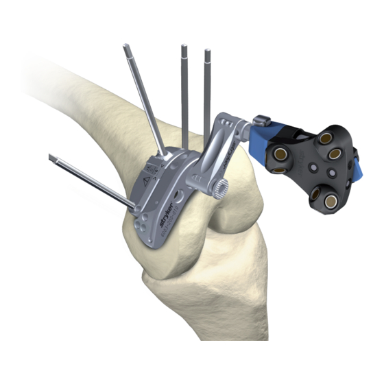
- Page 9 Hole for 1/8 in. (3.175 mm) headless pin insertion Adjustment Block 4 Prealign and Prefixate Cutting Guide on Bone 4.1 Position the Cutting Guide on the bone with preadjusted varus/valgus, flexion/extension and resection level settings for preliminary fixation. 4.2 For preliminary fixation insert a 1/8 in. (3.175 mm) headless pin into the swivel of the adjustment block as depicted in the detail above.
- Page 10 Instructions Hole for 1/8 in. (3.175 mm) headless pin insertion (4 total) 6 Fixate Adjustment Block 6.1 Insert two1/8 in. (3.175 mm) headless pins into the adjustment block for fixation as depicted in the detail above. Ensure that the adjustment block is stable and can not move relative to the bone.
- Page 11 7 Adjust Resection Level 7.1 Use the screwdriver as depicted above for resection level adjustment. The scale is not calibrated. Refer to the navigation screen for adjustment. Hole for 1/8 in. (3.175 mm) headless pin insertion (4 total) Cutting Block 8 Final Fixation of Cutting Block 8.1 Insert two 1/8 in.
- Page 12 Instructions 9 Bone Cut 9.1 Insert the blade for cut. 9.2 Proceed to cut. Disassembling Instructions for Cleaning Prior to cleaning and sterilization follow thein- structions below for optimum cleaning and sterilization performance: 1 Remove Tracker and Tracker Adapter. 2 Remove all pins. 3 Insert the screwdriver into the screwdriver interface.
-
Page 13: Cleaning Recommendations
Cleaning Recommendations Sterilization Recommendations To obtain optimum performance and help We recommend manual precleaning and prevent product damage, it is essential machine cleaning method. The Navigated that the following sterilization procedure MIS Jig has cleaning group IV. Refer to the is followed for the Navigated MIS Jig. -
Page 14: Handling And Storage
Troubleshooting Guidelines ACTION PROBLEM CAUSE Return Tracker and Tracker The Tracker can not rotate The interface is bent/ Adapter to service. or be mounted onto inter- damaged. face and does not lock in position. Return Tracker Adapter and Cut- The interface is bent/ ting Guide to service. -
Page 15: Specifications
Specifications* Model: Navigated MIS Jig-A REF 6003-200-010 Navigated MIS Jig-B REF 6003-200-020 Tracker Adapter REF 6003-200-030 40.5 x 43.1 x 11 mm(1.57 x 1.69 x 0.43 in.) Tracker Adapter Size: 54.5 x 25 x 31 mm (2.14 x 0.9 x 1.24 in.) Jig A/B Weight: 130 g (4.58 oz) with Tracker Adapter assembled... - Page 16 Manufactured and Distributed by: Stryker Leibinger GmbH & Co. KG Bötzinger Straße 41 79111 Freiburg, Germany t: +49 761 4512 0 Distributed by: Stryker Navigation 4100 East Milham Avenue Kalamazoo, MI 49001 USA t: 1 269 323 7700 Translated Equivalent:TD6003200713...
Need help?
Do you have a question about the Navigated MIS Jig-A and is the answer not in the manual?
Questions and answers