Advertisement
For Additional Technical Assistance Call +1.509.332.1890
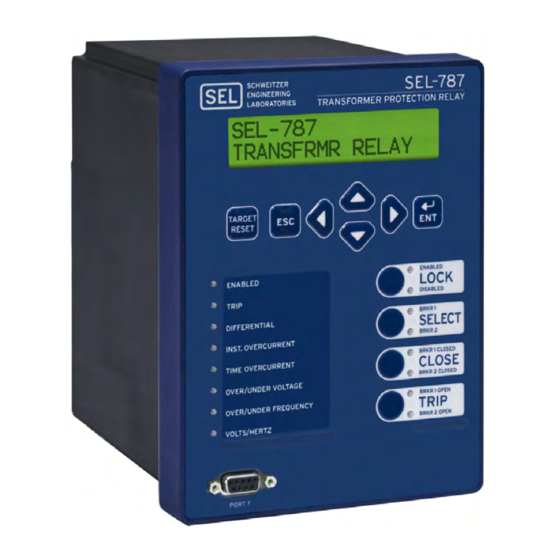
Express Installation Guide
SEL-787 Transformer Protection Relay
Package Contents
Blank Pushbutton LED Label
Blank Target LED Label
Label Removal Tool
UP
UP
LEFT
198-0424
RIGHT
198–0424
Panel Cutout Template
Product Literature CD
No. 8-32 Mounting Screws,
Configurable Label Kit
Gasket, & Serial Port Cover
Advertisement
Table of Contents

Related Manuals for Sel 787


Summary of Contents for Sel 787
- Page 1 For Additional Technical Assistance Call +1.509.332.1890 Express Installation Guide SEL-787 Transformer Protection Relay Package Contents Blank Pushbutton LED Label Blank Target LED Label Label Removal Tool LEFT 198-0424 RIGHT 198–0424 Panel Cutout Template Product Literature CD No. 8-32 Mounting Screws, Configurable Label Kit Gasket, &...
- Page 2 SEL-2600 Series ≤ 1000 m 4 Digital Inputs / 3 Digital Outputs External RTD Module With ST Option SEL 2812 compatible ST FO Cable** (Optional) Fiber-Optic Serial Port (Optional) 3 Digital Inputs / 4 Digital Outputs / 1 Analog Output V–...
- Page 3 Rack Mounting You can mount the SEL-787 in a sheltered indoor environment (a building or an enclosed cabinet) that does not exceed the temperature rating of –40°C to +85°C. For mounting consideration the relay dimensions are shown below. New Control Center 1.
- Page 4 Connections Connections are shown for the SEL-787 with Ethernet, Fiber Optic EIA-232, IRIG-B, EIA-485, 3 DI/4 DO/1 AO Option, 8 DI Option, and Voltage/Current (3 AVI/1 ACI) Option. Refer to the SEL-787 manual for additional details and other options. Wire sizes for connections are dictated by the terminal blocks and expected load currents. You may use the following table...
- Page 5 Connect 4-wire wye-connected PTs or open-delta connected PTs as shown in the typical connections diagram. For other PT connection options refer to Section 2 in the SEL-787 manual. Connect neutral current input to terminals 09 and 10. Card Slot Z: Current Inputs Card Connect Winding 1 and Winding 2 phase current inputs as shown in the typical connections diagram.
- Page 6 Communication With Relay There are two ways of communicating with the SEL-787 Motor Relay. You can communicate with the relay using the Human Machine Interface (HMI) on the front panel or through serial port communications with a computer. For ®...
- Page 7 The relay is equipped with a wide selection of protection and logic elements. Section 4 in the SEL-787 manual, describes all the protection and logic functions of the relay, together with all the necessary settings.
- Page 8 Step 4. Save the revised setting file into the database, and then with the settings still open, click the Send Active Settings icon and then click OK when prompted to upload the revised settings into relay. Step 5. Perform relay verification and commissioning tests per your requirements. Refer to Section 10 in the SEL-787 manual for details on relay testing. NOTE: Be sure to evaluate and confirm all relay settings before implementing this application on an actual transformer.
Need help?
Do you have a question about the 787 and is the answer not in the manual?
Questions and answers