Table of Contents
Advertisement
Quick Links
Advertisement
Table of Contents

Related Manuals for Vents VN E 80


Summary of Contents for Vents VN E 80
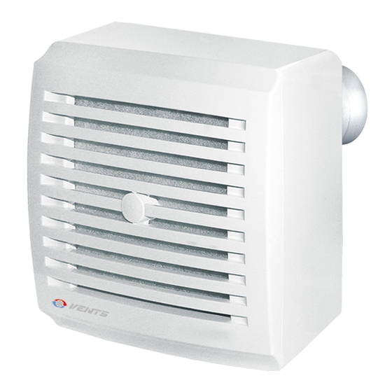
- Page 1 CENTRIFUGAL EXTRACT FAN VN E 80 User’s manual www.ventilation-system.com...
-
Page 2: Table Of Contents
CONTENTS Delivery set ................................................6 Brief description ..............................................6 Designation key ..............................................8 Operation guidelines ............................................9 Installation................................................15 Connection to power mains ........................................28 Timer and humidity sensor adjustment ....................................32 Technical maintenance ........................................... 34 Storage and transportation regulations ....................................36 Manufacturer’s warranty .......................................... - Page 3 This user’s manual is a main operating document intended for technical, maintenance, and operating staff. The manual contains information about the purpose, technical details, operating principle, design, and installation of the VN E unit (-s) and all of its (their) modifications. Technical and maintenance staff must have theoretical and practical training in the field of ventilation systems and should be able to work in accordance with workplace safety rules as well as construction norms and standards applicable in the territory of the country.
- Page 4 FOLLOW THE USER’S MANUAL REQUIREMENTS TO ENSURE DURABLE AND TROUBLE-FREE OPERATION OF THE UNIT. Disconnect the unit from power supply prior to any connection, servicing, maintenance, and repair operations. Only qualified electricians with a work permit for electrical units up to 1000 V are allowed for installation and maintenance.
- Page 5 • Do not use the unit in a hazardous or explosive environment containing spirits, gasoline, insecticides, etc. • Do not close or block the intake or extract vents in order to ensure the efficient air flow. • Do not sit on the unit and do not put objects on it.
-
Page 6: Delivery Set
The fan can be mounted to the ceiling or onto a wall with air extraction into a ventilation shaft or a matching diameter round air duct. Each specific fan model differs by mounting type: - VN E 80 (К) / VN-1 E 80 (К) — wall mounting - VNV-1 E 80 E KV / KP / KVK —... - Page 7 VNV-1 E 80 KP, VNV-1 E 80 KVK, VN-1 E 80 K VN E 80 К meet special fire safety requirements and are designed for preventing smoke fume penetration into the serviced spaces through air ducts in the event of a fire.
-
Page 8: Designation Key
DESIGNATION KEY VN V X 80 K X X Additional options ТР — timer — user-adjustable timer Н — intermittent operation switch — humidity sensor Connection of air ducts from another room _ — not available — left-hand side — right-hand side —... -
Page 9: Operation Guidelines
Conventional designation of casings for fans X 80 K K — fire-safety damper 80 — connection diameter [mm] Casing type — fire-safety casing — fire-safety casing for ceiling mounting — plastic casing OPERATION GUIDELINES The fan is rated for connection to single-phase AC 220...240 V/50 Hz power mains. Ingress protection rating against access to hazardous parts and water ingress is IP55. - Page 10 The outside and connecting dimensions as well as the appearance of the units are given on Fig. 1 through 11. VN E 80 VN-1 E 80...
- Page 11 VN E 80 K VN-1 E 80 K...
- Page 12 VNV-1 E 80 KV VNV-1 E 80 KP...
- Page 13 VNV-1 E 80 KVK VNV-1 E 80...
- Page 14 KP 80 KV 80 KVK 80...
-
Page 15: Installation
1.7. Mount the fan casing complete with the scroll and secure it to the mounting surface with self-tapping screws (Fig. 34). 1.8. Complete steps 1.2 to 1.4. in the reverse order. VN E 80 fan installation steps: 2.1. Mark and drill a hole for the fan outlet connection according to one of the 4 possible placement variants (Fig. 25 to 28). - Page 16 3.9. Rotate the fan and align the mounting holes of the casing and those of the swing damper, and secure the fan with self- tapping screws (Fig. 44). 3.10. Complete steps 1.2 to 1.4. in the reverse order. VN E 80 K fan installation steps: 4.1. Complete step 3.1.
- Page 17 5.4. Route the power cable into the fan casing. 5.5. Fill the gaps between the fan casing and the wall opening with mortar, sealing foam etc. 5.6. Once the installation has been completed, cover the casing with the cardboard spacer to prevent damage or contamination during the fit-out works in the space (Fig.
- Page 18 1, turn the damper 180° and insert it into the pipe. For sectional air vents use rectangular-section steel ducts or SPIROVENT spirally wound air vents. For air duct connections use ALUVENT or THERMOVENT flexible air ducts.
- Page 19 VN E 80, VN-1 E 80, VN E 80 К, VN-1 E 80 K installation options...
- Page 20 VNV-1 E 80 KV and VNV-1 E 80 KVK installation options VNV-1 E 80 KP installation options...
- Page 21 Fan placement options relative to walls and ceiling VN E 80 and VN-1 E 80 VN E 80 and VN-1 E 80 VN E 80 К and VN-1 E 80 K VN E 80 К and VN-1 E80 K VN E 80 and VN-1 E 80 VN E 80 and VN-1 E 80 VN E 80 К...
- Page 22 VN-1 E 80 installation steps...
- Page 23 VN E 80 installation steps VN-1 E 80 K installation steps...
- Page 25 VNV-1 E 80 KV, VNV-1 E 80 KVK, VNV-1 E 80 KP installation steps...
- Page 26 PROTECTIVE CARDBOARD SPACER...
-
Page 28: Connection To Power Mains
CONNECTION TO POWER MAINS To connect the fan to the electric mains: — Run the cable through the gland in the rear part of the casing (Fig. 57). — Strip the insulation leaving 7–8 mm long tips. — Undo two screws and remove the control unit lid (Fig. 57). —... - Page 29 Electrical circuit diagram for connecting the base model fan External switch (e.g. P2-1-300) is used to set the fan to one of the two available speeds or disable it manually. S(SW) External switch (e.g. P2-1-300) is used to set the fan to one of the two available speeds simultaneously with switching on the lights in the room or disable the fan when the lights are switched off.
- Page 30 Electrical circuit diagram for connecting fans equipped with the timer, user-adjustable timer, intermittent operation mode switch or humidity sensor — fan, — distribution box, — light bulb, — light switch (symbolic representation). Fan control The timer circuit board contains a DIP switch which controls the initial state of the fan. Mode 1 In the position the fan is initially disabled.
- Page 31 Т — timer Manual actuation of external switch S1 enables the fan and switches on the lights with a 50 second activation delay. Once external switch S1 is returned to the initial position the fan shuts down after a 6 minute timer delay. ТР...
-
Page 32: Timer And Humidity Sensor Adjustment
TIMER AND HUMIDITY SENSOR ADJUSTMENT DO NOT USE A METAL SCREWDRIVER, KNIFE, ETC. FOR ADJUSTMENT OPERATIONS NOT TO DAMAGE THE CIRCUIT BOARD. WARNING! The control board circuit is live! Disconnect the fan from power supply prior to any adjustment operations. The fan is supplied with a special plastic screwdriver for adjusting the settings. -
Page 34: Technical Maintenance
TECHNICAL MAINTENANCE Technical maintenance includes periodic filter replacement and cleaning the fan surfaces from dust and dirt. The impeller blades require thorough cleaning every 6 months. The filter must be replaced on a need-to-do basis, but at least every 6 months. -
Page 36: Storage And Transportation Regulations
STORAGE AND TRANSPORTATION REGULATIONS • Store the unit in the manufacturer’s original packaging box in a dry closed ventilated premise with temperature range from +5 ˚C to +40 ˚C and relative humidity up to 70 %. • Storage environment must not contain aggressive vapors and chemical mixtures provoking corrosion, insulation, and sealing deformation. -
Page 37: Manufacturer's Warranty
MANUFACTURER’S WARRANTY • The product is in compliance with EU norms and standards on low voltage guidelines and electromagnetic compatibility. We hereby declare that the product complies with the provisions of Electromagnetic Council Directive 2014/30/EU, Low Voltage Directive 2014/35/EU and CE-marking Directive 93/68/EEC. This certificate is issued following test carried out on samples of the product referred to above. - Page 38 • Redesign or engineering changes to the unit. • Replacement and use of any assemblies, parts and components not approved by the manufacturer. • Unit misuse. • Violation of the unit installation regulations by the user. • Violation of the unit control regulations by the user. •...
- Page 39 Quality Inspector's Stamp Sold by (name and stamp of the seller) Manufacture Date Purchase Date...
- Page 40 Certificate of acceptance VN V Е 80 K KV 80 plastic casing KP 80 fire-proof casing KVK 80 plastic casing with fire damper The fan is recognized as serviceable. V22-1EN-07...
Need help?
Do you have a question about the VN E 80 and is the answer not in the manual?
Questions and answers