Subscribe to Our Youtube Channel
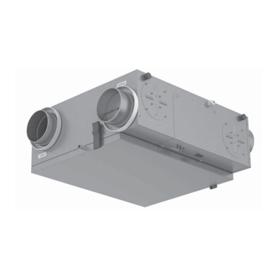
Summary of Contents for Vents Frigate HRV 120 SR
- Page 1 USER MANUAL Frigate HRV 120 SR Frigate ERV 120 SR Heat (energy) recovery ventilation unit...
-
Page 2: Table Of Contents
CONTENTS Safety requirements ....................3 Introduction ......................... 5 Use ........................... 5 Included in the box ....................5 Designation key ......................5 Technical data ......................6 Design and operation ....................7 Mounting and installation guidelines ..............8 Condensate Drainage ....................8 Connection to power supply ................. -
Page 3: Safety Requirements
SAFETY REQUIREMENTS • During installation and operation, observe all codes and safety standards for your locale. • Safe grounding must be provided! • Check the unit for possible damages prior to connecting it to power supply. Make sure the unit does •... - Page 4 Do not touch the unit controls Use the unit only for its intended with wet hands. Do not carry out purpose. Do not connect clothes the installation and maintenance dryers or similar equipment to operations with wet hands. the ventilation system. Do not wash the unit with water.
-
Page 5: Introduction
INCLUDED IN THE BOX One ventilation unit One user manual One packing box DESIGNATION KEY Frigate HRV 120 SR Unit type HRV: Heat recovery ventilation ERV: Energy recovery ventilation Air capacity [CFM] Spigot orientation S: suspended mounting R: recirculation damper... -
Page 6: Technical Data
TECHNICAL DATA The unit is designed for indoor installation and Frigate HRV 120 SR Frigate ERV 120 SR operation at the ambient air temperature ranging from RPM, min 2885 +34 °F (+1 °C) up to +122 °F (50 °C) and RH max. 80 %. -
Page 7: Design And Operation
DESIGN AND OPERATION FRESH COLD AIR FROM OUTSIDE STALE AND WARM AIR FROM ROOM SUPPLY FILTER EXTRACT FILTER RECIRCULATION DAMPER DRAIN PIPE HEAT RECOVERY CORE AIR SUPPLIED TO ROOM UTILIZED EXHAUST AIR EXHAUST FAN SUPPLY FAN DRAIN PAN CONTROL PANEL BACKDRAFT DAMPER ... -
Page 8: Condensate Drainage
CONDENSATE DRAINAGE HRV 120 SR must be connected to sewage system. Connect the drain pipe, the U-trap (not included) and the sewage system with metal, plastic or rubber hoses with the minimum hose slope angle 3°. Fill the system with water prior to connecting the unit to power supply and make sure the U-trap is always fi lled with water. Check the drain system for correct operation and unhampered drainage to prevent condensed water accumulation and overfl ow. - Page 9 WARRANTY WILL NOT COVER EQUIPMENT DAMAGE OR FAILURE THAT IS CAUSED BY IMPROPER INSTALLATION. The unit is rated for connection to single-phase ac 120 V/ 60 Hz power supply source. The unit is equipped with a power cable and a plug and can be connected to any standard grounded outlet. The power cable is pre-wired to the terminal by default.
- Page 10 the range from 25 % up to 100 %. Connection terminals for connection of external controls SPEED CONTROL 1 2 3 4 5 6 7 8 910 1 2 3 4 5 6 7 8 910 Operation LED indicator STANDBY Power supply indicator Setup and external Three-position mode switch...
- Page 11 air damper or any other compatible climatic equipment is sent. Control signal parameters: • maximum current 1A; • maximum voltage 250 V. Access to the control circuit board and connection of the external control equipment: • unscrew the front part of the control panel; •...
-
Page 12: Maintenance
Press the MODE button three times. LED1 and LED2 indicators start blinking three times as you enter the setup mode. Adjust the exhaust and supply fan speed. Press and hold the MODE button. After that the LED1 and LED2 indicators light up and the speed setting is saved. DEFROSTING MODE. - Page 13 water solution. Let the heat recovery core dry out and re-install it into the unit. Fan maintenance (once per year). Regular filter and heat recovery core maintenance may not completely prevent dust ingress into the unit fans. Clogged filter reduce supplied air volume to the room. Clean the fans with a soft cloth or a brush.
-
Page 14: Troubleshooting
TROUBLESHOOTING Trouble Probable reason Remedy Have a qualifi ed electrician check for No power supply. connections and troubleshoot a connection error if required. The fan is not started. Turn the unit off . Troubleshoot the motor Motor jam, contaminated impeller blades. jamming. -
Page 15: Warranty
Production meets standard operating requirements in the USA and Canada. VENTS US warrants to the original purchaser of the Frigate HRV 120 SR / Frigate ERV 120 SR unit that it will be free from defects in materials or workmanship for a period of 60 months from the date of original purchase. The VENTS US warrants to the original purchaser of the HRV 120 SR / Frigate ERV 120 SR unit that the integrated control unit will be free from defects in materials and workmanship for a period of 24 months from the date of original purchase. - Page 16 V-US102(FRIGATE_HRV-ERV120SR)EN-02...


Need help?
Do you have a question about the Frigate HRV 120 SR and is the answer not in the manual?
Questions and answers