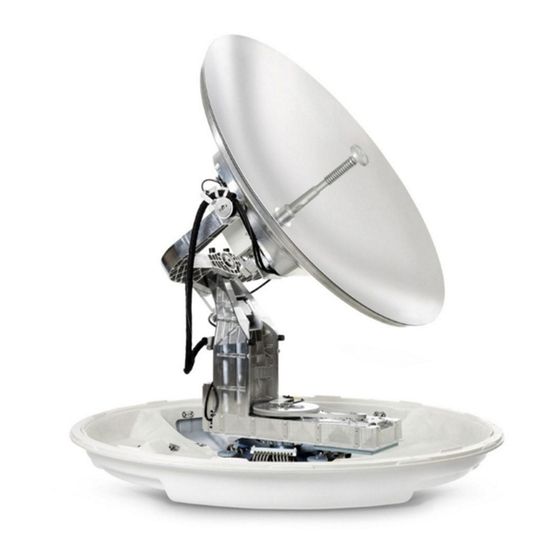
COBHAM SAILOR 1000 XTR Ku Field Replacement Procedure
Power detector housing
Hide thumbs
Also See for SAILOR 1000 XTR Ku:
- Installation and operation manual (159 pages) ,
- Replacement manual (9 pages) ,
- Installation manual (191 pages)
Table of Contents
Advertisement
Quick Links
Field Replacement Procedure
SAILOR 1000 XTR Ku – Power Detector Housing
Brief Summary:
Field replacement document for replacing the Power Detector Housing.
Spare part:
S-67-176325 Power Detector Housing
Location of the part:
Following legal entities are trading as / doing business as Cobham SATCOM
Thrane & Thrane A/S, Kgs. Lyngby, Denmark
Sea Tel Inc., Concord USA
Field replacement procedure
Cobham SATCOM
Global Technical Service dept.
Date: October 2021
Document Number:
97-178197-A
www.cobham.com/satcom
Advertisement
Table of Contents

Related Manuals for COBHAM SAILOR 1000 XTR Ku


Summary of Contents for COBHAM SAILOR 1000 XTR Ku
- Page 1 Field replacement document for replacing the Power Detector Housing. Spare part: S-67-176325 Power Detector Housing Location of the part: Following legal entities are trading as / doing business as Cobham SATCOM Thrane & Thrane A/S, Kgs. Lyngby, Denmark Sea Tel Inc., Concord USA www.cobham.com/satcom...
- Page 2 Replacing the part: 1. Open the service hatch, loosen the 8 screws. Do not use a power tool! Access the pedestal through the hatch. Power off the ADU (at the ADU power on/off switch at the antenna control module). Remove the feed horn with a suitably sized wrench.
- Page 3 5. With a Torx25 screw driver loosen the four screws (do not remove them entirely) to remove the RF pack. 6. Turn the RF pack anti-clockwise and lift it off using the two handles. Continue the replacemnt below deck. 7. Remove the 2 shafts to loosen the waveguide arm using an Allen key 4 mm.
- Page 4 10. Remove the four screws holding the power detector housing. 11. Remove the faulty power detector housing and O-ring from the BUC. 12. Mount the O-ring and replace the power detector housing onto the BUC. 13. Tighten with 2.5 Nm. 14.
- Page 5 Important! Turn the RF Package as far as possible clockwise, and keep it there until the screws are tightened. 18. Tighten the four screws at 4.5 Nm using a Torx 25 screwdriver. 19. Connect the cables: a) 2x LNB cables (socket wrench 8mm, 1.0 Nm), b) BUC cable (wrench, 2.0 Nm), c) Cable to Power Detector housing (insert carefully as the PCB is very fragile)
- Page 6 21. Switch on the antenna at the ADU power on/off switch at the antenna control module and check that the antenna goes through the POST (antenna can move freely). Close the hatch. Apply copper grease to thread of the 8 screws. Grease type: Rocol 250, Nulon 90, or Abcon 790.
Need help?
Do you have a question about the SAILOR 1000 XTR Ku and is the answer not in the manual?
Questions and answers