Table of Contents
Advertisement
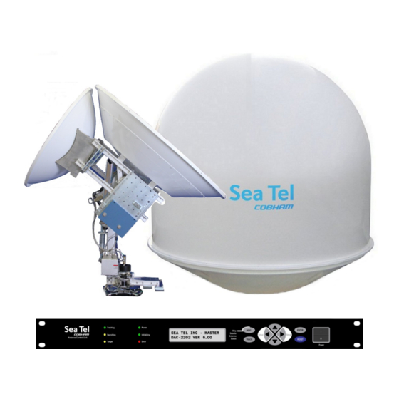
Sea Tel 6011-4 C/Ku-Band TVRO Satellite Antenna
Installation Manual
This technical data is subject to US Government export control in accordance with the
Export Administration Regulations. Export of this data to any foreign country, or disclosure
of this data to a Non-US person, may be a violation of Federal law.
Sea Tel, Inc.
(trading as Cobham SATCOM)
4030 Nelson Avenue
Concord, CA 94520
Tel: +1 (925) 798-7979
Fax: +1 (925) 798-7986
Web:
http://www.cobham.com/satcom
August 31, 2018
EAR Controlled - ECCN EAR99
EAR Controlled - ECCN EAR99
Thrane & Thrane A/S
(trading as Cobham SATCOM)
Lundtoftegaardsvej 93 D, 2800 Kgs.
Lyngby, Denmark
Tel: +45 3955 8800
Fax: +45 3955 8888
satcom.ohc@cobham.com
Email:
Document. No. 99-133136-A
Advertisement
Table of Contents
Troubleshooting

Related Manuals for COBHAM Sea Tel 6011-4


Summary of Contents for COBHAM Sea Tel 6011-4
- Page 1 Sea Tel 6011-4 C/Ku-Band TVRO Satellite Antenna Installation Manual EAR Controlled - ECCN EAR99 This technical data is subject to US Government export control in accordance with the Export Administration Regulations. Export of this data to any foreign country, or disclosure of this data to a Non-US person, may be a violation of Federal law.
- Page 2 Sea Tel is an ISO 9001:2015 registered company. Certificate Number 13690 originally issued March 14, 2011 and was renewed/reissued on March 13, 2018. Cobham SATCOM declares that the Sea Tel TVRO Maritime Satellite Earth Stations are in compliance with The Radio Equipment Directive 2014/53/EU. The full text of 2014/53/EU this Self Declaration of Conformity for this equipment is contained in this manual.
- Page 3 Sea Tel Inc. 4030 Nelson Ave., Concord California, 94520, USA T: +1 (925) 798-7979 F: +1 (925) 798-7986 RED Declaration of Conformity Sea Tel Inc. declares under our sole responsibility that the products identified below are in conformity with the requirements of: RED Directive 2014/53/EU concerning maritime Radio Equipment as described in the harmonized standards listed below and the mutual recognition of their conformity.
- Page 4 Sea Tel 6011-4 This Page Intentionally Left Blank EAR Controlled - ECCN EAR99...
-
Page 5: Table Of Contents
Table of Contents Sea Tel 6011-4 1. SAFETY ............................1-1 2. ST60 SERIES SYSTEM CONFIGURATION(S) ..................2-1 2.1............................ 2-1 YSTEM ABLES 2.2........................ 2-1 THER NPUTS TO THE YSTEM 2.3. 6011-4 S ..................2-1 IMPLIFIED LOCK IAGRAM OF A YSTEM 3. - Page 6 Sea Tel 6011-4 Table of Contents 4.3.1. Connecting the ADE AC Power Cable ..................4-11 4.3.2. Connecting the BDE AC Power Cables ..................4-11 4.3.3. Connecting the ADE-BDE IF Coaxes ..................4-11 4.3.4. Antenna Control Unit Connections ................... 4-11 4.3.5.
- Page 7 Table of Contents Sea Tel 6011-4 11.1. E ) ........11-1 LECTRONIC ALIBRATION OF ELATIVE NTENNA OSITION FFSET 11.1.1. You Found a Large AZ TRIM value: ..................11-2 11.1.2. You Observe “Home” Pointing is LEFT of the Bow-line: ............. 11-2 11.1.3.
- Page 8 Sea Tel 6011-4 Table of Contents 16.4. T ..........16-6 ARGET ATELLITE NOTHER ATELLITE 16.5. Q 6011-4 QOR TVRO A ..16-8 UICK EFERENCE LOWCHART HANGING ATELLITES WITH A NTENNA YSTEM 17. FUNCTIONAL TESTING ....................... 17-1 17.1. ACU / A ......................
- Page 9 Table of Contents Sea Tel 6011-4 21.9. E ......................21-6 NVIRONMENTAL PECIFICATIONS 21.9.1. Climatic Conditions ......................... 21-6 21.9.2. Chemically Active Substances ....................21-6 21.9.3. Transit Conditions ........................21-6 21.10. B ........................21-7 ELOW ECKS QUIPMENT 21.10.1. Antenna Control Unit (ACU) ..................... 21-7 21.10.2.
- Page 10 Sea Tel 6011-4 Table of Contents This Page Intentionally Left Blank EAR Controlled - ECCN EAR99...
-
Page 11: Safety
Failure to comply with these precautions or with specific warnings elsewhere in this manual violates safety standards of design, manufacture and intended use of the equipment. Sea Tel Inc (dba Cobham SATCOM) assumes no liability for the customer's failure to comply with these requirements. - Page 12 Sea Tel 6011-4 Safety This Page Intentionally Left Blank EAR Controlled - ECCN EAR99...
-
Page 13: System Cables
6011-4 System Configuration(s) Sea Tel 6011-4 6011-4 System Configuration(s) The 6011-4 Stabilized Antenna system is used for TeleVision Receive Only (TVRO) satellite communications. It is comprised of two major groups of equipment: the Above Decks Equipment (ADE) and the Below Decks Equipment (BDE). - Page 14 Sea Tel 6011-4 ST60 Series System Configuration(s) EAR Controlled - ECCN EAR99...
-
Page 15: Site Survey - Shipboard
Site Survey - Shipboard Sea Tel 6011-4 Site Survey - Shipboard There are three objective of the site survey. The first is to find the best place to mount the antenna and the BDE. The second is to identify the length and routing of the cables and any other items or materials that are required to install the system. -
Page 16: Mounting Foundation
Sea Tel 6011-4 Site Survey - Shipboard 3.3. Mounting Foundation 3.3.1. Mounting on Deck or Deckhouse While mounting the ADE on a mast is a common solution to elevate the ADE far enough above the various obstructions which create signal blockages, sometimes the best mounting position is on a deck or deckhouse top. -
Page 17: Mounting Height
Site Survey - Shipboard Sea Tel 6011-4 with throats equivalent to the thickness of the thinnest base material. 8. For an ADE mounted greater than 0.6 meters (24 inches) above the ship’s structure, at least one (1) foot rung should be added. Additional rungs should be added for every 0.3 meter (12 inches) of pedestal height above the ship’s structure. -
Page 18: Raked Masts
Sea Tel 6011-4 Site Survey - Shipboard sailing mast and adapted for mounting the ever-increasing array of antennae which ships need to communicate with the world. This drawing of a vertical mast shows the preferred mounting of the ADE center-line above the plane of the radar. Alternatively the ADE is mounted below the plane of the radar signal Vertical masts are most commonly found on cargo ships –... -
Page 19: Girder Masts
Site Survey - Shipboard Sea Tel 6011-4 3.5.3. Girder Masts Girder masts are large platforms atop a pair of columns. Just like girder constructions in buildings, they are relatively stiff athwart ship – in their primary axis – but less stiff longitudinally and torsionally. -
Page 20: Cables
Sea Tel 6011-4 Site Survey - Shipboard The Satellite Receiver, router, computers and any other associated equipment should be properly mounted per their design. 3.8. Cables During the site survey, walk the path where the cables will be installed. Pay particular attention to how cables will be installed;... -
Page 21: Acu Power Cable/Outlet
Site Survey - Shipboard Sea Tel 6011-4 3.8.3. ACU Power Cable/Outlet The AC power for the ACU and the ADE is not required to be from a UPS (same one that supplies power to the ADE), but it is recommended. - Page 22 Sea Tel 6011-4 Site Survey - Shipboard This Page Intentionally Left Blank EAR Controlled - ECCN EAR99...
-
Page 23: Installation
Installation Sea Tel 6011-4 Installation Your antenna pedestal comes completely assembled in its radome. This section contains instructions for unpacking, final assembling and installing of the equipment. It is highly recommended that trained technicians install the system. Your antenna may have been ordered in any one of a variety of different diameter radomes. The installation instructions for most common radome sizes for your system are below. -
Page 24: Installing The Ade
Sea Tel 6011-4 Installation 4.3. Installing the ADE The antenna pedestal is shipped completely assembled in its radome. Please refer to the entire Site Survey chapter of this manual. Base Hatch Access - Mounting the radome directly on the deck or platform prevents access to the hatch in the base of the radome unless an opening is designed into the mounting surface to allow such entry. -
Page 25: Install 76" Radome To The Mounting Platform
Installation Sea Tel 6011-4 6. Attach shackles and four part web lifting sling arrangement to the eyebolts. Attach a suitable length tagline to one of the eyebolts. 8. After hoisted into place the lifting eyes are to be removed and replaced with the... - Page 26 Sea Tel 6011-4 Installation 9. Man the tag line and have the crane continue lifting the ADE up and hover above the mounting site on the ship. 10. Carefully route AC Power, ground strap/cable (see Grounding info below) and coax cables through the cable passage in the bottom center of the radome base and through the cable channel under the lower base plate of antenna.
- Page 27 Installation Sea Tel 6011-4 17. Pass the coaxial and power cables through the cable mounting frame. HINT: Again, It may be easier to connect or tie- wrap the coaxes and power cable temporarily. 18. Re-install the cable mounting frame onto...
-
Page 28: Grounding The Pedestal
Sea Tel 6011-4 Installation 4.4. Grounding the Pedestal The antenna pedestal must be grounded to the hull of the ship. A grounding point is provided on the upper base plate to ground the pedestal. A ground wire, of appropriate gauge for it’s length, must be provided to ground the pedestal to the mounting platform that it will be bolted to (this is usually on or near the mounting surface). -
Page 29: Removing The Az Shipping/Stow Restraint
Installation Sea Tel 6011-4 4.5.1. Removing the AZ Shipping/Stow Restraint The AZ shipping/stow restraint is formed by a buckle web strap wound around the azimuth post toe weight and passed through stow clips in the base of the radome. 2. To un-restrain azimuth rotation of the... - Page 30 Sea Tel 6011-4 Installation To un-restrain the elevation axis of the antenna, unthread the two hex nuts. Using a ¾” open end wrench, remove the hex nuts and washer from the stow pin-bolt. 4. Remove the stow pin-bolt from the bracket.
-
Page 31: Removing The Cl Shipping/Stow Restraint
Installation Sea Tel 6011-4 8. Tighten the hex nut to prevent the hardware from loosening while in the un-stowed configuration. 9. Verify that the antenna rotates freely through its full elevation range of motion. 4.5.3. Removing the CL Shipping/Stow Restraint... -
Page 32: Cable Installation
Sea Tel 6011-4 Installation 4.1. Cable Installation 4.1.1. Shipboard Cable Installation CAUTION: Rough handling, tight bending, kinking, crushing and other careless handling of the cables and their connectors can cause severe damage. The cables must be routed from the above-decks equipment mounting location through the deck and through various ship spaces to the vicinity of the below-decks equipment. -
Page 33: Connecting The Below Decks Equipment
Installation Sea Tel 6011-4 4. Install your Multi-Switch, Satellite Receivers, Television Sets, Computer and any other below decks equipment that are part of your installation. 4.3. Connecting the Below Decks Equipment Connect this equipment as shown in the System Block Diagram. Install the equipment in a standard 19 inch equipment rack or other suitable location. -
Page 34: Terminal Mounting Strip (Tms) Connections
Sea Tel 6011-4 Installation 4.3.4.4. M&C Connection to the ACU If you wish to use a computer to Monitor & Control the antenna through the Antenna Control Unit there are two possible connections that can be made. One choice is a serial connection from J3 “M&C”... -
Page 35: Final Checks
Installation Sea Tel 6011-4 connected, but is not required because there is a GPS device already installed in your antenna. • TxA- screw terminal is used to provide a Pseudo GPS (GGA and GLL formats) output to other system components such as a Satellite Modem. -
Page 36: Fine Balance And Monitoring Motor Drive Torque
Sea Tel 6011-4 Installation At the ACU: From the ACU - REMOTE BALANCE parameter: Enable balance mode (refer to your ACU manual). The screen should now display “REMOTE BALANCE ON”. At the Antenna: 2. At the Antenna: Balance the antenna with the elevation near horizon (referred to as front to back balance) by adding, or subtracting, small counter-weights. - Page 37 Installation Sea Tel 6011-4 The Cross Level displayed above the reference line indicates that the CL axis is being driven • CCW (Left in CL). Example: The antenna pictured in the screen capture below is imbalanced so that it is “Right Heavy”.
- Page 38 Sea Tel 6011-4 Installation This Page Intentionally Left Blank 4-16 EAR Controlled - ECCN EAR99...
-
Page 39: Basic Setup Of The Acu
Basic Setup of the ACU Sea Tel 6011-4 Basic Setup of the ACU 5.1. Operator Settings Refer to the Operation chapter of this manual to set the ship information. Latitude and longitude should automatically update when the GPS engine mounted on the antenna pedestal triangulates an accurate location, but you may enter this information manually to begin. -
Page 40: Save New Parameters
Sea Tel 6011-4 Basic Setup of the ACU SEARCH DELAY SWEEP INC SYSTEM TYPE Leave at factory Defaults GYRO TYPE 2 (NMEA/SBS) Setup – Ships Gyro Compass POL TYPE Setup – Polarity Selection AND POL OFFSET Setup – Optimizing Polarization... -
Page 41: Setup - Setting Up The Dual Reflectors
Setup – Setting Up the Dual Reflectors Sea Tel 6011-4 Setup – Setting Up the Dual Reflectors In a new installation, it is very important that each of the two reflectors is set up, and optimized, correctly. Several things should be investigated prior to setting any of the parameters in preparation for setting up each of the reflectors: Refer to chapter 6 to identify what gyro compass type, and the subsequent GYRO TYPE parameter setting you will use. -
Page 42: Optimizing Ku-Band (Reflector B)
Sea Tel 6011-4 Setup – Setting Up the Dual Reflectors 6.2. Optimizing Ku-Band (Reflector B) Tracking Menu – Set band selection to KuHi-Band (chapter 8) 2. Satellite Menu - Tracking Receiver settings (chapter 7): MHz - Set to the desired tracking frequency, in MHz, of the network/carrier you want to track on. -
Page 43: Setup - Ships Gyro Compass
Setup – Ships Gyro Compass Sea Tel 6011-4 Setup – Ships Gyro Compass The Ships Gyro Compass connection provides true heading (heading of the ship relative to true North) input to the system. This allows the ACU to target the antenna to a “true” azimuth position to acquire any desired satellite. - Page 44 Sea Tel 6011-4 Setup – Ships Gyro Compass This Page Intentionally Left Blank EAR Controlled - ECCN EAR99...
-
Page 45: Setup - Tracking Receiver
Setup – Tracking Receiver Sea Tel 6011-4 Setup – Tracking Receiver 8.1. Determining the IF Tracking Frequency (FREQ or MHz) The IF Tracking parameter is a calculated value entered into the ACU’s MHz Sub-Menu. The value itself is calculated by using the formula RF- LO = IF. -
Page 46: Volt
Sea Tel 6011-4 Setup – Tracking Receiver 8.4. Volt 8.4.1. TVRO Application The Voltage setting in the ACU is a selection of one of four receiver options and is based on the Downlink RF Polarization from the satellite. In a TVRO application, receiver voltage is used for proper port (receive polarization) selection. -
Page 47: Setup - Band & Reflector Select
Setup - Band & Reflector Select Sea Tel 6011-4 Setup - Band & Reflector Select 9.1. Band, Low Noise Block Converter Operation and Reflector Selection: When you set the band selection to C, or X, you are selecting the C-Band reflector (REFL A) and its LHCP &... - Page 48 Sea Tel 6011-4 Setup - Band & Reflector Select This Page Intentionally Left Blank EAR Controlled - ECCN EAR99...
-
Page 49: Setup - Targeting
Setup – Targeting Sea Tel 6011-4 Setup – Targeting The procedure for optimizing the targeting of the antenna to land on or near a desired satellite (within +/-1 degree) is outlined below. 10.1. Optimizing QOR Dual Reflector Targeting First assure that Heading (SHIP Menu) has been set correctly. -
Page 50: Auto Trim
Sea Tel 6011-4 Setup – Targeting Tone - Set to OFF if you want to use low band satellite frequencies (10.7-11.7 GHz). Set to ON if you want to use high band satellite frequencies (11.7-12.75 GHz). Volt - Set to HORZ if you will be tracking on a Horizontal signal from the satellite. Set to VERT if you will be tracking on a Vertical signal from the satellite. -
Page 51: El Trim
Setup – Targeting Sea Tel 6011-4 Allow several minutes for the antenna to “peak” on the signal, and then record the Azimuth and Elevation positions while peaked on satellite (these are the Peak positions). Again, assure that it has acquired the satellite that you targeted! 4. - Page 52 Sea Tel 6011-4 Setup – Targeting This Page Intentionally Left Blank 10-4 EAR Controlled - ECCN EAR99...
-
Page 53: Setup - Home Flag Offset
Setup – Home Flag Offset Sea Tel 6011-4 Setup – Home Flag Offset Home Flag Offset is used to calibrate the relative azimuth value of the antenna to the bow line of the ship. This assures that the encoder input increments/decrements from this initialization value so that the encoder does not have to be precision aligned. -
Page 54: You Found A Large Az Trim Value
Sea Tel 6011-4 Setup – Home Flag Offset 11.1.1. You Found a Large AZ TRIM value: If Targeting has been optimized by entering a large value of AZ TRIM: First, verify that you are able to repeatedly accurately target a desired satellite (within +/- 1.0 degrees). Then you can use the AZ TRIM value to calculate the value of HFO you should use (so you can set AZ TRIM to zero). -
Page 55: You Observe "Home" Pointing Is Right Of The Bow-Line
Setup – Home Flag Offset Sea Tel 6011-4 11.1.3. You Observe “Home” Pointing is RIGHT of the Bow-line: In this example, I observe that the Home position is past the bow line. 2. I estimate that it is about 90 degrees. -
Page 56: Mechanical Calibration Of Relative Antenna Position (Home Flag Offset)
Sea Tel 6011-4 Setup – Home Flag Offset writing mode and then press the ENTER to save the HFO value in the PCUs NVRAM. You must drive the antenna CW in azimuth until the home switch is actuated, or re-initialize the antenna to begin using the new HFO value you have entered and saved. - Page 57 Setup – Home Flag Offset Sea Tel 6011-4 the metal home flag tab CW 45° and tighten the clamp bolt (use caution not to tighten too much and strip the nylon hardware).. You will have to estimate this 45° rotation based on the 60° spacing of the hex bolt centers.
- Page 58 Sea Tel 6011-4 Setup – Home Flag Offset This Page Intentionally Left Blank 11-6 EAR Controlled - ECCN EAR99...
-
Page 59: Searching Operation
Setup – Searching Sea Tel 6011-4 Setup – Searching 12.1. Searching Operation The ACU will initiate an automated search pattern after AGC falls below the current Threshold setting (indicates that satellite signal has been lost). The SEARCH DELAY parameter sets the amount of delay, in seconds that the ACU will wait after AGC has fallen below the threshold value before it starts a search. -
Page 60: Inclined Orbit Search Pattern
Sea Tel 6011-4 Setup – Searching If the desired signal is found (AND network lock is achieved in the satellite modem) at this position, or anywhere within the search pattern, the ACU will terminate search and go into Tracking mode. If the desired signal is not found the ACU will wait SEARCH DELAY seconds and then begin the search pattern again. -
Page 61: No Gyro Search Pattern
Setup – Searching Sea Tel 6011-4 reached. When the end of the search pattern is reached, the ACU will retarget the antenna to the calculated Azimuth and Elevation point. If the desired signal is found (AND network lock is achieved in the satellite modem) at this position, or anywhere within the search pattern, the ACU will terminate search and go into Tracking mode. -
Page 62: Changing The Search Parameters
Sea Tel 6011-4 Setup – Searching 12.2. Changing the Search Parameters The information above described what some of these parameters need to be set to for a specific search pattern. Below are some additional pieces of information on the other parameters and the steps to change any one of these parameters. -
Page 63: Az Step Size
Setup – Searching Sea Tel 6011-4 12.2.3. AZ STEP SIZE For proper DishScan® operation this parameter must be set to factory default value of 0000. To manually update, press the LEFT arrow key to bring the cursor up under the least significant character. -
Page 64: Sweep Inc
Sea Tel 6011-4 Setup – Searching 12.2.8. SWEEP INC This parameter MUST be set for the desired azimuth sweep speed of a No Gyro search or the sweep increment dimension of an Inclined Orbit search (refer to the search pattern information above). -
Page 65: Setup - Blockage & Rf Radiation Hazard Zones
Setup – Blockage & RF Radiation Hazard Zones Sea Tel 6011-4 Setup – Blockage & RF Radiation Hazard Zones This section discusses how to set up blockage, or RF Radiation Hazard, zones. 13.1. Radiation Hazard and Blockage Mapping (AZ LIMIT parameters) The ACU can be programmed with relative azimuth sectors (zones) where blockage exists or where transmit power would endanger personnel who are frequently in that area. - Page 66 Sea Tel 6011-4 Setup – Blockage & RF Radiation Hazard Zones In a “Dual Antenna” installation, this logic output is also used to control a Dual Antenna Arbitrator panel to switch the TXIF & RXIF signals from Antenna “A” to Antenna “B” when Antenna “A” is blocked, and vice versa.
- Page 67 Setup – Blockage & RF Radiation Hazard Zones Sea Tel 6011-4 ZONE 3 begins (AZ LIMIT 5) at 156 degrees Relative and ends (AZ LIMIT 6) at 172 degrees Relative. Multiply these Relative positions by 10. Enter AZ LIMIT 5 value of 1560 and AZ LIMIT 6 value of 1720.
- Page 68 Sea Tel 6011-4 Setup – Blockage & RF Radiation Hazard Zones EXAMPLE 3 - One blockage Zone: A ship has a Sea Tel antenna mounted on the center line of the ship. A mast is forward and an engine exhaust stack is aft. In this example the Stack does NOT block the satellite, only the mast forward does.
-
Page 69: Save New Parameters
Setup – Blockage & RF Radiation Hazard Zones Sea Tel 6011-4 ZONE 3 begins (AZ LIMIT 5) at 155 degrees Relative and ends (AZ LIMIT 6) at 205 degrees Relative. Multiply these Relative positions by 10. Enter AZ LIMIT 5 value of 1550 and AZ LIMIT 6 value of 2050. - Page 70 Sea Tel 6011-4 Setup – Blockage & RF Radiation Hazard Zones This Page Intentionally Left Blank 13-6 EAR Controlled - ECCN EAR99...
-
Page 71: Setup - Other Parameters
Setup – Other Parameters Sea Tel 6011-4 Setup – Other Parameters 14.1. SETUP Parameter display and entry menus. Press and hold BOTH the LEFT and the RIGHT arrow keys for 6 seconds to access to the system setup parameters (at the EL TRIM selection). Press BOTH the LEFT and the RIGHT arrow keys momentarily to access to the SAVE NEW PARAMETERS parameter. -
Page 72: Satellite Reference Mode
Sea Tel 6011-4 Setup – Other Parameters If DishScan® is OFF and the Step Integral parameter is set to 0000, you will get a constant ERROR 0016 (DishScan® error) and you will see zeros flashing in the lower left of the Azimuth and Elevation ENTRY menu displays. -
Page 73: Stowing The Antenna
Stowing the Antenna Sea Tel 6011-4 Stowing the Antenna This antenna must be properly stowed if the ship will be underway while AC power to the Above Decks Equipment (ADE) is de-energized. Failure to do so may void your warranty. -
Page 74: Installing The El Shipping/Stow Restraint
Sea Tel 6011-4 Stowing the Antenna 15.1.2. Installing the EL Shipping/Stow Restraint The EL shipping/stow restraint is formed by a stow pin-bolt mounted through a bracket and is engaged into a hole/slot in the elevation driven sprocket when the dish is at zenith (90 degrees elevation). -
Page 75: Installing The Cl Shipping/Stow Restraint
Stowing the Antenna Sea Tel 6011-4 Remove the washer from the stow pin-bolt and unthread the hex nut from the bolt. 6. Put one of the washers onto the stow pin- bolt and insert it into the bracket toward the elevation driven sprocket. -
Page 76: Removing The Shipping/Stow Restraints Prior To Power-Up
Sea Tel 6011-4 Stowing the Antenna 2. If not already removed, remove an adjustable bumper by removing the bottom nut from one end of the locking bar. If not already loosened, loosen the top nut up toward the rubber bumper. -
Page 77: Removing The El Shipping/Stow Restraint
Stowing the Antenna Sea Tel 6011-4 15.2.2. Removing the EL Shipping/Stow Restraint The EL shipping/stow restraint is formed by a stow pin-bolt mounted through a bracket and is engaged into a hole/slot in the elevation driven sprocket when the dish is at zenith (90 degrees elevation). -
Page 78: Removing The Cl Shipping/Stow Restraint
Sea Tel 6011-4 Stowing the Antenna Remove the washer from the stow pin-bolt and thread one of the two hex nuts onto the bolt and tighten. 6. Put one of the washers onto the stow pin- bolt and insert it into the bracket toward the elevation driven sprocket. - Page 79 Stowing the Antenna Sea Tel 6011-4 2. To un-restrain the cross-level axis of the antenna use a 7/16“ open end wrench to loosen the nut on the top side of the locking bar (either end of the bar). Remove the bottom nut off of that adjustable bumper.
- Page 80 Sea Tel 6011-4 Stowing the Antenna This Page Intentionally Left Blank 15-8 EAR Controlled - ECCN EAR99...
-
Page 81: Operation
Operation Sea Tel 6011-4 Operation The information below reflects normal operation of the antenna from the antenna control unit. It assumes that: • The antenna has been properly installed • Home Flag Offset, targeting trims & polarization have been optimized •... -
Page 82: Target Froma C-Band Satellite T O Another C-Band Satellite
Sea Tel 6011-4 Operation Press ENTER again to access the SATELLITE – SAT longitude entry window and set the satellite longitude to 180.0W and press the ENTER key. • The ACU will now calculate the azimuth, elevation and polarization angles for the desired satellite (from the ships latitude &... - Page 83 Operation Sea Tel 6011-4 First, if we do not already know the tracking receiver settings that we will use for the Ku-Band linear satellite at 160W, we should look up the information online (using Lyngsat.com, or other similar web site).
-
Page 84: Target A Ku-Band Satellite From A C-Band Satellite
Sea Tel 6011-4 Operation 16.3. Target a Ku-Band Satellite From A C-Band Satellite We are now tracking the C-Band circular satellite at 160W. The current Azimuth of the C-Band reflector is 213.6 degrees and the Elevation is at 59.7 degrees. - Page 85 Operation Sea Tel 6011-4 Press ENTER again to access the SATELLITE – SAT longitude entry window and set the satellite longitude to 170.0W and press the ENTER key. • The ACU will now calculate the azimuth, elevation and polarization angles for the desired satellite (from the ships latitude &...
-
Page 86: Target From A Ku-Band Satellite To Another Ku-Band Satellite
Sea Tel 6011-4 Operation 16.4. Target From A Ku-Band Satellite To Another Ku-Band Satellite We are now tracking the Ku-Band linear satellite at 170W. The current Azimuth of the Ku-Band reflector is 229.9 degrees and the Elevation is at 52.6 degrees. - Page 87 Operation Sea Tel 6011-4 Press ENTER again to access the SATELLITE – SAT longitude entry window and set the satellite longitude to 190.0W and press the ENTER key. • The ACU will now calculate the azimuth, elevation and polarization angles for the desired satellite (from the ships latitude &...
-
Page 88: System
Changing Satellites - DAC-2202 Ver 6.08 With a 6011-4 QOR TVRO Antenna System Basic button pushing in any one of the sub-menus is; Use the LEFT and RIGHT arrow keys to bring up, and move, the cursor to select a character. Use the UP or DOWN arrow keys to increment or decrement the selected character to the desired value. Tone OFF AGC 1234 Status... -
Page 89: Functional Testing
Functional Testing Sea Tel 6011-4 Functional Testing If not already ON, Turn ON the power switch on the front panel of the ACU. 17.1. ACU / Antenna System Check Turn ACU power ON. Turn antenna pedestal/RF equipment power ON 2. Press RESET on the ACU front panel. Verify the display shows "SEA TEL INC - MASTER" and the ACU software version number. -
Page 90: Blockage Simulation Test
Sea Tel 6011-4 Functional Testing 17.4. Blockage Simulation Test Blockage output function is used to modify the behavior of tracking and searching when there is a known blockage zone. The ACU provides a contact closure to ground on the SW2 terminal of the TMS when the antenna is pointed within any one of the blockage/hazard zones or the system is searching, targeting, unwrapping or is mis-pointed by 0.5 degrees or more (FCC TX Mute function for Transmit/Receive systems... - Page 91 Functional Testing Sea Tel 6011-4 Press and hold the RIGHT arrow key to drive azimuth down until displayed AGC drops 100 counts (approx. 2-3 dB) (Do not drive antenna so far that AGC falls below threshold) 6. Press the TRACK key to re-enable tracking.
- Page 92 Sea Tel 6011-4 Functional Testing This Page Intentionally Left Blank 17-4 EAR Controlled - ECCN EAR99...
-
Page 93: Installation Troubleshooting
Scheduled Inspections section of this manual may be accomplished by technician/an engineer. Maintenance of the ODE should only be performed by technicians/engineers who are authorized by Cobham SATCOM. Only authorized Partners who have received factory training on this equipment will be able to file a claim for warranty reimbursement. -
Page 94: Acu Status Displays "Remote Not Responding
Sea Tel 6011-4 Installation Troubleshooting display status) the cables plugged into J1 Gyro Compass, then J2 NMEA, then J3 M&C to see if one of these cables is shorting the ACU power. Call your dealer to report this failure and arrange for repair service. -
Page 95: 360:1 Synchro
Installation Troubleshooting Sea Tel 6011-4 2. The display changes in the direction opposite of the movement of the ship. Switch the secondary leads S1 and S2. Caution: there is 90 VAC between them! Verify that when the ship changes direction the display shows change in the same direction. If the direction is correct but the heading is incorrect go to step C. - Page 96 Sea Tel 6011-4 Installation Troubleshooting This Page Intentionally Left Blank 18-4 EAR Controlled - ECCN EAR99...
-
Page 97: Maintenance
Maintenance Sea Tel 6011-4 Maintenance 19.1. C-Band Feed Assembly Polarity Selection: The Dual-Polarity C-Band TVRO Feed Assembly has two C-Band LNBs installed on it. One LNB will be LHCP and the other will be RHCP. The polarity if these two can be reversed if desired (the LHCP LNB will become RHCP and the RHCP will become LHCP when the polarity select knob is rotated 90 degrees from the “Normal”... -
Page 98: Replacing The Ku-Band Lnb
Sea Tel 6011-4 Maintenance Reverse Polarity selected (either location 180° apart) 4. Pull the locking pin to release polarity select knob rotation. Rotate the polarity select knob 90 degrees and release the locking pin. 6. Rotate the polarity select knob slightly... - Page 99 Maintenance Sea Tel 6011-4 If you are replacing the LNB with the same style LNB, loosen the Allen set screws on the existing LNB mounting collar (three set screws, 120 degrees apart) and extract it from the mounting collar. If you are changing the...
-
Page 100: Optimizing Ku-Band Linear Polarization
Sea Tel 6011-4 Maintenance 8. NOTE: Check and if required, use trim weights to re-balance the antenna if you have replaced a Brainwave Quad LNB with a Quattro Quad LNB. 9. Close the radome hatch or re- install the radome top and tighten radome hardware. -
Page 101: Bluetooth Installation & Operation
Bluetooth Installation & Operation Sea Tel 6011-4 Bluetooth Installation & Operation 20.1. Prerequisites To use a Bluetooth device, as described in the information below, the MINIMUM requirements are: • You must have a Sea Tel Series 09 antenna with MK2 PCU, a Series 10 antenna or a Series 11 antenna. -
Page 102: Installing The Bde Bluetooth Hardware
Sea Tel 6011-4 Bluetooth Installation & Operation 20.3. Installing the BDE Bluetooth Hardware The IOGear USB Bluetooth is shown below, other manufacturer/models may be used. At the below decks, or portable laptop, computer insert the Bluetooth Transmitter into an available USB port. -
Page 103: Removing The Ade Bluetooth Hardware
Bluetooth Installation & Operation Sea Tel 6011-4 If the Bluetooth hardware is not to remain installed, refer to the sections below to remove the hardware from ADE & BDE, before returning to normal operation. 6. When use of diagnostic mode is completed, refer to Operation mode. -
Page 104: Installing Software Via Bluetooth
Sea Tel 6011-4 Bluetooth Installation & Operation 20.7. Installing Software via Bluetooth You can update the MK2 PCU software, and/or the DAC software, using the Bluetooth connection. NOTE: You can NOT use the Bluetooth connection to update software in the CommIF, SCPC Receiver, 400MHz Modems or the Motor Driver Enclosure (MDE). -
Page 105: Tvro Technical Specifications
6011-4 TVRO Technical Specifications Sea Tel 6011-4 6011-4 TVRO Technical Specifications The specifications of your antenna system are below. For Naval Engineering level information on this subject, please refer to Antenna Installation Guideline – Site Arrangement, document number 130040_A available on the Sea Tel Dealer Support Site. -
Page 106: Qor Tm Dual Reflector Configuration
Sea Tel 6011-4 6011-4 TVRO Technical Specifications 21.2. Dual Reflector Configuration: 21.2.1. Antenna Assembly - 60” C-Band TVRO The antenna assembly is comprised of the Dish, feed assembly and LNB. A variety of LNBs could be used, refer to LNB specification for the LNB that is provided with your system: Reflector Diameter 1.5 m (58 inch) -
Page 107: Interchangeable Lnb Options
6011-4 TVRO Technical Specifications Sea Tel 6011-4 21.3. Interchangeable LNB Options This antenna can be easily fitted with a variety of LNB assemblies. The feed is capable of receiving linear or circular polarization however the LNB must match the satellite programming type desired. Below are the LNBs which may be used with this system. -
Page 108: Mk 2 Pedestal Control Unit (Pcu)
Sea Tel 6011-4 6011-4 TVRO Technical Specifications 21.4. MK 2 Pedestal Control Unit (PCU) The PCU Assembly contains 3 Printed Circuit Boards (PCBs). Connectors AC Power 100-240 VAC, 2A-1A Mini USB GPS Input RJ-11 connector Motor Control DA-15S connector 70/140 MHz... -
Page 109: Mh Z Base & Pedestal Unlimited Azimuth Modems (3 Channel )
6011-4 TVRO Technical Specifications Sea Tel 6011-4 21.6. 400 MHz Base & Pedestal Unlimited Azimuth Modems (3 Channel) Combined Signals (-1,-2) Pass-Thru 950-3200 MHz RX IF, Injected 22Khz Tone DC LNB Voltage Select 400 MHz Pedestal M&C Connectors: RX IF L-Band... -
Page 110: Ade Pedestal Power Requirements
Sea Tel 6011-4 6011-4 TVRO Technical Specifications Cracks in, or other damage to, the radome base can be repaired using typical fiberglass repair techniques and proper sealing of the inside and outside surfaces. Edges of holes in the radome base must be properly sealed to prevent moisture from being absorbed into the layered construction of the radome base. -
Page 111: Below Decks Equipment
6011-4 TVRO Technical Specifications Sea Tel 6011-4 21.10. Below Decks Equipment 21.10.1. Antenna Control Unit (ACU) Refer to the information in the Specifications chapter of this Manual. 21.10.2. Terminal Mounting Strip (TMS) Refer to the information in the Specifications chapter of this Manual. -
Page 112: Multi-Conductor Cables (Customer Furnished)
Sea Tel 6011-4 6011-4 TVRO Technical Specifications 21.11.3. Multi-conductor Cables (Customer Furnished) Due to the voltage loss across the multi-conductor cables, Sea Tel recommends the following wire gauge for the AC & DC multi-conductor cables used in our standard pedestal installations:... -
Page 113: Drawings
DRAWINGS Sea Tel 6011-4 DRAWINGS The drawings listed below are provided as a part of this manual for use as a diagnostic reference. 22.1. 6011-4 Model Specific Drawings Drawing Title 134116-801_A System, 6011-4 in 76” Radome 22-3 134115-1_A1 System Block Diagram, 6011-4... - Page 114 Sea Tel 6011-4 DRAWINGS This Page Intentionally Left Blank 22-2 EAR Controlled - ECCN EAR99...
- Page 115 SINGLE LEVEL MFG BILL OF MATERIAL FIND QTY PART NO REV DESCRIPTION REFERENCE DESIGNATOR 1 EA 134117-1 GENERAL ASS'Y, 6011-4, C/KU 1 EA 134792-1 RADOME ASS'Y, GA INSTALL, 76 IN, TVRO 1 EA 132463-1 LNBF, QUAD, KU, INVERTO, MODIFIED (NOT SHOWN) 1 EA 125411-3 M DAC-2202, SCPC RCVR, 9 WIRE IF (NOT SHOWN)
- Page 116 This drawing and specifications are the property FINISH: APPROVED DATE: 76 IN DOME of Cobham PLC. Neither this document, the 134115 SYSTEM BLOCK DIAGRA, 6011-4 TVRO information, or the specifications disclosed shall be reproduced or transferred in whole or in part...
- Page 117 SINGLE LEVEL MFG BILL OF MATERIAL FIND QTY PART NO REV DESCRIPTION REFERENCE DESIGNATOR 1 EA 134117-1 GENERAL ASS'Y, 6011-4, C/KU 1 EA 133732-1 A1 FEED TUBE ASS'Y, C-BAND, DUAL RECEIVE 2 EA 134164-1 LNB, C-BAND, DRO, 8225RF 1 EA 134257-1 ANTENNA ASS'Y, 6011-4, 40 IN, KU-BAND 1 EA 132463-1 LNBF, QUAD, KU, INVERTO, MODIFIED...
- Page 118 SINGLE LEVEL MFG BILL OF MATERIAL FIND QTY PART NO REV DESCRIPTION REFERENCE DESIGNATOR 1 EA 131857-1 B1 BASE MODEM RACK PANEL ASS'Y, 4CH TVRO 1 EA 116676 D ASSEMBLY, TERMINAL MOUNTING STRIP 1 EA 130854-2 MODEM ASS'Y, 400MHZ FSK, 4CH,BDE, RS 1 EA 128001-8BLU A1 CABLE ASS'Y, RG-179 COAX, F(M) TO SMA 1 EA 128385-12BLU...
-
Page 122: Antenna Assy, Circular, C Band, 60 In, Tvro
Page 3 of 3 BOM Explosion Report Item Number: 134184-1 Description: ANTENNA ASSY, CIRCULAR, C BAND, 60 IN, TVRO Item Revision: B.01 ECO-00025499 Date as of: 08/30/2018 12:38:40 PM PDT Find Num Inventory Unit (LN6) Number Description / Title BOM Notes REF pcs 97-134184 ANTENNA ASS'Y, C-BAND, CIRC, 60IN, TVRO... - Page 123 REVISION HISTORY REV ECO# DATE DESCRIPTION 8542 05/10/11 RELEASE TO PRODUCTION. WAS REVISION X2. UPDATED NOTES. 9933 09/27/12 ADDED "CIRCULAR" TO TITLE. 10092 11/21/12 DIM. 45 WAS 22.5 . 13547 04/21/2014 ITEM 1 WAS 128641 LIND MOUNTING HOLE PATTERN 50 56 57 45°...
-
Page 124: Antenna Assy, 6011-4, 40 In, Ku-Band
Page 2 of 3 BOM Explosion Report Item Number: 134257-1 Description: ANTENNA ASSY, 6011-4, 40 IN, KU-BAND Item Revision: ECO-00008546 Date as of: 08/30/2018 12:38:40 PM PDT Find Num Inventory Unit (LN6) Number Description / Title BOM Notes 122092 REFLECTOR MACHINING, 40 IN ECO-00008543 122237 A.02... - Page 125 REVISION HISTORY REV ECO# DATE DESCRIPTION 8542 05/09/11 RELEASED TO PRODUCTION. WAS REVISION X1. MODIFIED NOTES. DETAIL B SCALE 1 : 4 NOTES: (UNLESS OTHERWISE SPECIFIED) MANUFACTURE PER SEA TEL STANDARD 122298. APPLY EPOXY PER ASSEMBLY INSTRUCTIONS. APPLY LOCTITE 2760 PER SEA TEL SPEC. 121730 AND ALLOW TO CURE PRIOR TO INSTALLING ITEM 2.
- Page 126 SINGLE LEVEL MFG BILL OF MATERIAL FIND QTY PART NO REV DESCRIPTION REFERENCE DESIGNATOR 1 EA 131057-1 H ENCLOSURE ASS'Y, PCU, 09G2, 3 CH, 232 1 EA 123861 MOUNTING PLATE 2 EA 126288-17 UNISTRUT, 1-5/8 H-CHANNEL, 17 IN, AL 2 EA 127566-2 A2 MOUNTING BLOCK ASS'Y, COUNTER WEIGHT 4 EA 124588-1021 STANDOFF, HEX, F/F, 1/4-20 X .50 OD X...
- Page 127 REVISION HISTORY REV ECO# DATE DESCRIPTION 7398 07/12/10 RELEASED TO PRODUCTION WAS REVISION X2. RELOCATED ITEM 1 RELATIVE TO MOUNTING PLATE (ITEM 10). 8525 5-19-11 UPDATE TITLE BLOCK & STANDARD NOTES K.D.H. NOTES: UNLESS OTHERWISE SPECIFIED 1. MANUFACTURE PER SEATEL STANDARD 122298. USE OLCTITE 242 AT THIS LOCATION.
-
Page 128: Balance Weight Assy, Cl/El, 6011-4
Page 1 of 3 BOM Explosion Report Item Number: 134125-1 Description: BALANCE WEIGHT ASSY, CL/EL, 6011-4 Item Revision: ECO-00008546 Date as of: 08/30/2018 12:38:40 PM PDT Find Num Inventory Unit (LN6) Number Description / Title BOM Notes 108724-3 C.02 PLATE, COUNTER WEIGHT, 1/2 X 7-1/4 X 10 ECO-00008542 108724-1 C.02... - Page 129 REVISION HISTORY REV ECO# DATE DESCRIPTION 8542 05/12/11 RELEASED TO PRODUCTION. NO PRIOR REVISION. EQUIPMENT FRAME & PEDESTAL SHOWN FOR REFERENCE ONLY 58 58 NOTES: UNLESS OTHERWISE SPECIFIED MANUFACTURE PER SEA TEL STANDARD 122298. BALANCE WEIGHTS ARE SHOWN AS STARTING WEIGHTS ONLY.
- Page 130 SINGLE LEVEL MFG BILL OF MATERIAL FIND QTY PART NO REV DESCRIPTION REFERENCE DESIGNATOR 1 EA 128652-1 A2 RADOME TOP FAB, 76 IN, WHITE 1 EA 130395-1 A3 RADOME BASE ASS'Y, 76 IN, WHITE 1 EA 130390-2 KIT, HARDWARE, GA TO RADOME, RAISED 1 EA 130394-2 C1 KIT, HARDWARE, RADOME TO MAST, 12-HOL 4 EA 119801-012...
- Page 131 This drawing and specifications are the property FINISH: APPROVED DATE: WHITE INSTALL, 76 IN, TX/RX of Cobham PLC. Neither this document, the SNOW WHITE information, or the specifications disclosed shall DETAIL A be reproduced or transferred in whole or in part...
- Page 132 PART OF ITEM 3 PART OF G.A. PARTS OF THE FULL ASS'Y PART OF ARE OMITTED FOR CLARITY RADOME BASE SEE DETAIL C SECTION B-B (4 PLS) SCALE 1 : 4 ROTATE: 90 CW REDUCED THICKNESS AREA FOR STRAIN RELIEF INSTALLATION PER PROCEDURE 131226.
-
Page 134: Procedure, Radome Strain Relief Installation
Procedure, Radome Strain Relief Installation Purpose. To define the installation procedure for installing strain reliefs in “smooth base” radomes. Scope. This installation procedure applies to fiberglass radomes having Sea Tel’s standard four-hole mounting pattern, and M12 mounting hardware , in the 80-180 cm (34-66 in) nominal size range, typically referred to as “smooth”... - Page 135 Procedure, Radome Strain Relief Installation Making the holes PLANNING: Space has been allowed for up to 5 ea. strain reliefs, but, install only as many as needed. (Typically only 2-3 for TX/RX systems). Refer to Fig 2 then plan which hole positions to use. For 76-inch radomes lowest holes may be approx 1.5 inches from inside wall corner with floor (ref drawing 129416).
- Page 136 Procedure, Radome Strain Relief Installation Measure, mark and drill pilot holes CAUTION: The hole locations cannot be determined accurately from outside of the radome. Using full scale drawing 132234, provided in the strain relief kit, measure mark and drill pilot holes from the inside out, and using only light pressure, use the small drill bit, (~1/8”...
- Page 137 Procedure, Radome Strain Relief Installation Fig. 5 – Outside view. Rotate General Assembly (G.A.) Once cables have been installed, rotate General Assembly (G.A.), to ensure cables are routed properly and do not interfere with azimuth rotation. Fig. 6 – Inside view. Records.
- Page 138 Procedure, Radome Strain Relief Installation Strain relief positioning for 80-180 cm (34-66 in) smooth based radomes, (May use Sea Tel drawing 132234 as template.) Document No Page 5 of 6 131226 Rev A Form # 117140-B...
- Page 139 Procedure, Radome Strain Relief Installation Strain relief positioning for 193 cm (76-inch) radomes. (May use Sea Tel drawing 132234 as template.) Document No Page 6 of 6 131226 Rev A Form # 117140-B...
- Page 140 SINGLE LEVEL MFG BILL OF MATERIAL FIND QTY PART NO REV DESCRIPTION REFERENCE DESIGNATOR 1 EA 112657 MACHINING, TERMINAL MOUNTING STRIP 1 EA 126865-2 G PCB ASS'Y, TERMINAL MOUNTING STRIP, 5 1 EA 112936-36 D1 CABLE ASS'Y, D-SUB, 25 PIN, 36 IN 1 EA 116669-36 B1 CABLE ASS'Y, D-SUB, 9-PIN, 36 IN.
-
Page 142: Base Modem Rack Panel Assy, 4Ch Tvro, 400Mhz
Page 1 of 1 BOM Explosion Report Item Number: 131857-1 Description: BASE MODEM RACK PANEL ASSY, 4CH TVRO, 400MHZ Item Revision: B.01 ECO-00008545 Date as of: 08/31/2018 08:43:17 AM PDT Find Num Qty Inventory Unit (LN6) Number Description / Title BOM Notes 116880 PANEL MACHINING, RACK, BASE MUX... - Page 143 REVISION HISTORY REV ECO# DATE DESCRIPTION 8180 02-14-11 ITEM 50 QTY WS 6. ADD ITEM 52. UPDATE NOTES. 04-18-11 BALLOON 52 WAS 50. NOTES: UNLESS OTHERWISE SPECIFIED MANUFACTURE PER SEA TEL SPEC 122298. IDENTIFY PER SEATEL SPECIFICATION 122930 ( APPENDIX D) APPROX WHERE SHOWN. DESIGNER/ENGINEER: DRAWN BY: K.D.H.
Need help?
Do you have a question about the Sea Tel 6011-4 and is the answer not in the manual?
Questions and answers