Furuno FE-700 Operator's Manual
Navigational echo sounder
Hide thumbs
Also See for FE-700:
- Installation manual (61 pages) ,
- Service manual (58 pages) ,
- Operator's manual (43 pages)
Table of Contents
Advertisement
Advertisement
Table of Contents
Troubleshooting

Subscribe to Our Youtube Channel
Related Manuals for Furuno FE-700


Summary of Contents for Furuno FE-700
- Page 1 NAVIGATIONAL ECHO SOUNDER FE-700...
- Page 2 Printed in Japan All rights reserved. All rights reserved. Pub. No. OME-23660 Pub. No. OME-23660 ( ( YOSH YOSH ) ) FE-700 FE-700 Your Local Agent/Dealer Your Local Agent/Dealer FIRST EDITION : FIRST EDITION : JAN JAN. . 2000 2000 : : DEC DEC.
- Page 3 Immediately turn off the power at the switchboard if water leaks into the equipment. Continued use of the equipment can cause fire or electrical shock. Contact a FURUNO agent for service. Do not disassemble or modify the equipment. Fire, electrical shock or serious injury can result.
- Page 4 RECORD OF MODIFICATIONS IN THIS OPERATOR’S MANUAL Pub No. Software (Prog No.) Publicized for Display Unit submission to 02522970-01 type test by BSH Digital Depth Indicator (Feb/2000) 65-5-0100-001 OME-23660-F Digital Depth Indicator 65-5-0100-003 Dec/2000 OME-23660-G Display Unit Apr/2001 02522970-02 (Serial no. 2232-0618 and after) OME-23660-H ----...
-
Page 5: Table Of Contents
CONTENTS FOREWORD ... iv A Word to FE-700 Owners... iv Features ... iv SYSTEM CONFIGURATION ... v SPECIFICATIONS OF FE-700 …...SP-1 1 OPERATION ... 1 1.1 Control Description... 1 1.2 Indications, Markers ... 2 1.3 Turning On/Off ... 3 1.4 Tone and Brilliance... 3 1.5 Panel Dimmer ... -
Page 6: Foreword
ISO 9001 standards as certified by the Lloyd’s Register of Quality Assurance System. Features The FURUNO FE-700 is comprised of display unit and transducer unit. Echo sounding data is displayed on the bright 6.5-inch color TFT (Thin Film Transistor) LCD display. -
Page 7: System Configuration
TRANSDUCER PRINCIPLE OF OPERATION The FE-700 uses ultrasonic pulses to detect the seabed and other underwater objects. The display unit contains all basic electric circuits and logic processor. Electrical pulses are converted into acoustical energy in the transducer fitted on the ship’s hull. The processor measures the time of pulses travelling between the seabed and transducer and displays the water depths in the graphical form or other forms. - Page 8 Display Mode 1.10 Picture Advance Speed Slow mode Fast mode Range (m) Interval (min.) FE-700 6.5-inch color TFT LCD, 320 x 234 pixels 8 colors or 8 level monochrome 133 x 97 mm Unit ±2.5% on any range 0.5 m (200 kHz), 2.0 m (50 kHz) -10 to 30 m in 0.1 m steps, default 0 m...
- Page 9 1.11 User Setting 1.12 Auto Set Mode 1.13 Alarm 1.14 Logbook Display TRANSCEIVER CHARACTERISTICS (BUILT IN DISPLAY UNIT) Transmit Frequency Output Power DIGITAL DEPTH INDICATOR Display Depth Indication Power supply Coating color Waterproofing TRANSDUCER TYPE AND BEAMWIDTH 50B-6B (50 kHz): 200B-8B (200 kHz): INTERFACE Serial Input Data...
- Page 10 Input Alarm (Depth, Power) POWER SUPPLY ENVIRONMENTAL CONDITION Temperature Relative Humidity Waterproofing EMC Emission Category of Equipment Units Display Unit Distribution Box Matching Box Transducer COATING COLOR Display Unit Distribution Box/ Matching Box Control command for PC Contact closure signal, normal open or normal close, 250 VAC/ 200 VDC, 3A max.
-
Page 11: Operation
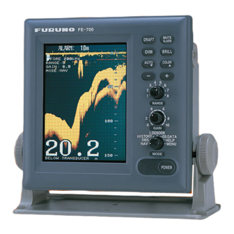
1 OPERATION 1.1 Control Description All operation of the FE-700 is carried out with the controls on the front panel of the display unit. Rotary controls respond immediately to your command but some touch keys require the successive operation. -
Page 12: Indications, Markers
1.2 Indications, Markers Display mode Gain setting Range setting Auto mode AUTO FORE RANGE: 4 GAIN: 5.5 MODE: NAV Depth alarm line Depth Explanation of depth (Below transducer, or below surface) Transducer in use ( when using transducer switch box. ) Alarm setting ALARM 15m... -
Page 13: Turning On/Off
1.3 Turning On/Off 1. Turning on: Press the POWER Switch. Self-test starts, showing the condition of the logic circuits. The program number is displayed. ROM: OK DRAM: OK SRAM: OK BATTERY: OK PROGRAM NO. 0252297002 2. Select a mode with the MODE Selector. The NAV position of the selector is recommended for general use. -
Page 14: Display Mode
1.6 Display Mode The Mode Selector choose the display mode among NAV, DBS (depth below surface), HISTORY, LOGBOOK, OS DATA, HELP, and MENU. 1.6.1 NAV mode The depth from the transducer to the seabed (bottom clearance) is shown on the screen. Note “BELOW TRANSDUCER”... - Page 15 1.6.4 LOGBOOK mode The LOGBOOK shows time, depth and own ship position in tabular form in a pop-up window. The logging is selected with the INTERVAL option on the menu among 5 s, 1 min and 2 min. (See section 2.6.) There are 60 pages and the total memory capacity is 720 points.
- Page 16 Enlarging data of interest You can enlarge one of the data indications as follows: 1. Press the [▲] or [▼] key to select the data you want to enlarge. Current section is circumscribed with the blue cursor. For example, select the depth cell. 2.
-
Page 17: Range Scale
1.7 Range Scale If the depth goes out of the correct display area, increase or decrease the range until the seabed appears near the center of the screen. Adjust the Range Control, and current range selection is shown in the range display window. RANGE In the AUTO mode, the range scale is automatically adjusted. -
Page 18: Shallow Depth Alarm
Monochrome (amber) is the default setting. The Strata display contains multiple colors depending on the reflectivity from underwater objects of the sounding pulses. Red is strongest, followed by brown, orange, yellow, blue, and light blue. 1.11 Shallow Depth Alarm The shallow depth alarm sounds when the seabed is shallower than the preset depth. -
Page 19: Menu Operation
2 MENU OPERATION 2.1 Menu Overview The menu has several functions for advanced operation. 1. Select MENU with the MODE Selector. CLUTTER AUTO (0 16) INTERFERENCE REJECT PICTURE ADVANCE SLOW FAST TREND INDICATOR INTERVAL 1 min 2 min ▼▲: To select item - +: To set option 2. -
Page 20: Picture Advance
2.4 Picture Advance The picture advance speed determines how quickly the vertical scan lines run across the screen. 1. Select MENU with the MODE Selector. 2. Select PICTURE ADVANCE by pressing the [▲] or [▼] key. 3. Press the [+] or [-] key to select speed FAST or SLOW, respectively. -
Page 21: System Menu
3 SYSTEM MENU 3.1 System Menu The system menu should be set just after installation and is not always necessary to be adjusted. If you change any items of the system menu or even if you open the system menu, the sounding picture will be cleared. -
Page 22: System Menu 1
INTERFACE: Selects I/O signal format between the FE-700 and external equipment; IEC format “1:95” (1995 version) or “1:98” (1998 version), or NMEA format. Default setting is IEC “1:98”. When selecting the “1:98”, DPT has max. range in use (See page 24). -
Page 23: System Menu 3
SYSTEM MENU 2 MENU SELECT 1 2 3 TIME ADJUST INTERNAL EXTERNAL TIME DIFFERENCE AUTO MANUAL TIME DIFF HOUR 0 (0 13) TIME DIFF MIN 0 (0 59) TIME DIFF SIGN - , + ▼▲: To select item - +: To set option Select other mode to exit. -
Page 24: Echo Quality Setting
This chapter describes functions useful for improving echo sounding performance. 4.1 Demonstration Display The demonstration program shows how the FE-700 works. 1. Turn off the equipment. 2. Press the POWER Switch while pressing any key. Release the key when the following EXTENSION MODE display appears . -
Page 25: Bottom Level
CAUTION If the level is set too low, the FE-700 may not be able to distinguish the bottom from fish echo and the depth indication may be unstable and if set to high the depth indication does not appear. -
Page 26: Operation Of Digital Depth
5 OPERATION OF DIGITAL DEPTH INDICATOR The Digital Depth Indicator FE-720 is an optional remote display. The panel illumination can be locally adjusted on the control panel or on the optional hand dimmer box. 5.1 Basic Operation 5.1.1 Turning on Press the POWER key. -
Page 27: Menu Operation
5.2 Menu Operation 5.2.1 Dimmer control The dimmer is controlled either with the DIM key, or the optional Dimmer Controller. The method of control must be selected on the menu. 1. Press the MENU key to display the main menu. MENU DIM CONTROL PANEL ONLY... -
Page 28: Diagnosis
5.2.4 Alarm You can set turn alarm on or off. In the ON mode, if the main display unit activates the alarm, the FE-720 also. 1. Press the MENU key to display main menu. 2. Press [▲] or [▼] to select ALARM. 3. -
Page 29: Maintenance, Troubleshooting
6 MAINTENANCE, TROUBLESHOOTING WARNING Do not open the cover. There are no user-serviceable parts inside. Refer any repair work to a qualified technician. 6.1 Checking Regular maintenance is essential for good performance. Checking the items listed in the table below on a regular basis will keep the equipment in good shape for years to come. -
Page 30: Troubleshooting
6.5 Troubleshooting The table below provides simple troubleshooting procedures which you may follow to restore normal operation. If you cannot restore normal operation, contact your dealer. SYMPTOM PROBABLE CAUSES No picture; no reading Low power supply measure Fuse blown Power cable damaged No echo sounding picture Transducer cable damaged Transducer cable connection... -
Page 31: Diagnostic Test
6.6 Diagnostic Test The diagnostic test checks the ROM, RAM, color bar and keyboard for proper operation. 1. Turn on the power while pressing any key. Release the keys when the following display appears. EXTENSION MODE TRANSDUCER SETTING TEST ▲: CLEAR MEMORY DEMONSTRATION ▼:... -
Page 32: Clearing The Memory
6.8 Clearing the Memory All menu settings can be cleared to start afresh. All default menu settings are restored when the memory is cleared. For your reference all default settings are shown in the menu tree at the end of this manual. -
Page 33: Menu Tree
7 MENU TREE MENU CLUTTER (AUTO, 0 16, 9) INTERFERENCE REJECT (OFF, IR1, IR2, IR3) PICTURE ADVANCE (SLOW, FAST) TREND INDICATOR (ON, OFF) INTERVAL (5 s, 1 min, 2 min) GO TO SYSTEM MENU? (NO, YES) SYSTEM MENU 1 SYSTEM MENU 2 SYSTEM MENU 3 EXTENSION MODE Any key + [POWER]... -
Page 34: Digital Interface (Iec 61162-1 Edition 2)
DIGITAL INTERFACE (IEC 61162-1 EDITION 2) 1. I/O Sentences Input sentences of channel 1 (NAV IN) RMA, RMC, GLL, GGA, VTG, ZDA Output sentences of channel 2 (NAV OUT) DBT, DPT, DBS (NMEA 0183) Transmission interval 1 s for any sentence Data transmission Data is transmitted in serial asynchronous form in accordance with the standard referenced in 2.1 of IEC 61162-1. - Page 35 2. Schematic Diagrams NAV IN port (listener) FE-702 02P6283 B10B-XH-A 236-410M1-10 NAV IN RD1_A RD1_B Load requirements as listener Isolation: Optocoupler Input Impedance: 560 ohms Max. Voltage: ±15V NAV OUT ports FE-702 B10B-XH-A 236-410M1-10 NAV OUT 1 TD1_A TD1_B 236-410 NAV OUT 2 M1-10 TD1_A...
- Page 36 3. Sentence Description DPT - Depth $--DPT,x.x,x.x,x.x*hh<CR><LF> | +----- 4 +--------- 3 +------------ 2 +---------------- 1 1. Water depth relative to trancsducer, in meters 2. Offset from transeducer, in meters(see notes 1 and 2) 3. Maximum range scale in use 4.
- Page 37 GLL - Geographic position - latitude/longitude $--GLL,llll.lll,a,yyyyy.yyy,a,hhmmss.ss,A,a*hh<CR><LF> +---------------- 3 +------+----------------------- 2 +---+----------------------------------- 1 1. Latitude, N/S 2. Longitude, E/W 3. UTC of position 4. Status: A=data valid, V=data invalid 5. Mode indicator(see note) 6. Checksum NOTE Positioning system Mode indicator: A = Autonomous D = Differential E = Estimated (dead reckoning)
- Page 38 GGA - Global positioning system (GPS) fix data $--GGA,hhmmss.ss,llll.lll,a,yyyyy.yyy,a,x,xx,x.x,x.x,M,x.x,M,x.x,xxxx*hh<CR><LF> +----+--------------------------------- 3 +---+--------------------------------------------- 2 +------------------------------------------------------------- 1 1. UTC of position 2. Latitude, N/S 3. Longitude, E/W 4. GPS quality indicator (see note) 5. Number of satllite in use,00-12, may be different from the number in view 6.
- Page 39 RMA - Recommended minimum specific LORAN-C data $--RMA,A,llll.lll,a,yyyyy.yy,a,x.x,x.x,x.x,x.x,x.x,a,a*hh<CR><LF> +-------------------------- 5 | +------------------------------ 4 +----+--------------------------------- 3 +---+-------------------------------------------- 2 +------------------------------------------------------- 1 1. Status: A=data valid, V=blink, cycle or SNR warning 2. Latitude, degrees N/S 3. Longitude, degrees E/W 4. Time difference A, microseconds 5.
- Page 40 RMC - Recommended specific GPS/TRANSIT data $--RMC,hhmmss.ss,A,llll.lll,a,yyyyy.yyy,a,x.x,x.x,xxxxxx,x.x,a,a*hh<CR><LF> +---+---------------------------- 4 +---+---------------------------------------- 3 +--------------------------------------------------- 2 +---------------------------------------------------------- 1 1. UTC of position fix 2. Status: A=data valid, V=navigation receiver warning 3. Latitude, N/S 4. Longitude, E/W 5. Speed over ground, knots 6. Course over ground, degrees true 7.
- Page 41 VTG- Course over ground and ground speed $--VTG,x.x,T,x.x,M,x.x,N,x.x,K,a*hh<CR><LF> | | | | | | | +------- 6 | | +--------- 5 +--+----------- 4 | | +--+----------------- 3 | | +--+----------------------- 2 +--+----------------------------- 1 1. Course over ground, degrees true 2. Course over ground, degrees magnetic 3.
-
Page 42: Parts Location, Parts List
9 PARTS LOCATION, PARTS LIST ANLG 02P6281 HEATSINK MAIN DISPLAY UNIT FE-701, INSIDE VIEW (SHIELD COVER REMOVED) MAIN BOARD 02P6280 PNL 02P6250 (Beneath) ISOLATION TRANSFORMER DISTRIBUTION BOX FE-702, INSIDE VIEW INTERFACE MEM 02P6282 CON 02P6283... - Page 43 FILTER ZCB2203-11 FUSE HOLDER FH043A FH043A TERMINAL BOARD ML250S1AXF-3P ML250S1AXF-3P JACK MJ-A10SRMD FUSE FGMB 1A 250V FGMB 1A 250V Model FE-700 Unit DISPLAY UNIT FE-701 DISTRIBUTION BOX FE-702 Ref.Dwg. CODE No. REMARKS 001-229-240 FE-701 001-229-220 FE-701 001-229-030 FE-702 001-229-190 FE-701...
Need help?
Do you have a question about the FE-700 and is the answer not in the manual?
Questions and answers