Table of Contents
Advertisement
Advertisement
Table of Contents
Troubleshooting

Related Manuals for Furuno FCV-582L


Summary of Contents for Furuno FCV-582L
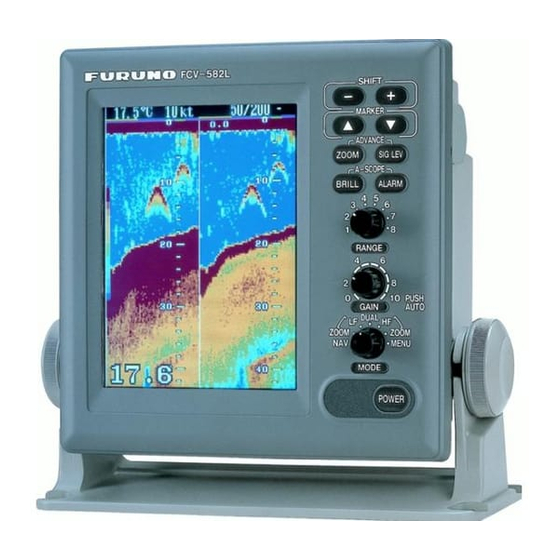
- Page 1 COLOR LCD SOUNDER FCV-582L MODEL...
- Page 2 9 - 5 2 , A s h i h a r a - c h o , N i s h i n o m i y a , J a p a n Te l e p h o n e : 0 7 9 8 - 6 5 - 2 111 Te l e f a x : 0 7 9 8 - 6 5 - 4 2 0 0...
- Page 3 Immediately turn off the power at the switchboard if water leaks into the equipment. Continued use of the equipment can cause fire or electrical shock. Contact a FURUNO agent for service. Do not disassemble or modify the equipment. Fire, electrical shock or serious injury can result.
-
Page 4: Table Of Contents
TABLE OF CONTENTS FOREWORD ... iii MENU TREE ... iv SYSTEM CONFIGURATION PRINCIPLE OF OPERATION OPERATIONAL OVERVIEW 1.1 Control Description ... 1 1.2 Indications, Markers ... 2 1.3 Turning On/Off the Power ... 3 1.4 Adjusting Tone and Brilliance ... 3 1.5 Selecting a Display ... -
Page 5: Foreword
FCV-582L displays underwater conditions in 16 colors (including background) on a bright 6.5-inch color TFT (Thin Film Tran- sistor) LCD. The main features of the FCV-582L are • Compact design permits installation where space is limited. • Bright 6.5-inch color LCD with tempera- ture compensated tone and brilliance con- trol. -
Page 6: Menu Tree
MENU TREE MENU NOISE LIMITER (OFF, NL1, NL2, NL3) CLUTTER (0 USER MARKER(VRM,WHITE,MARKER) MENU HUE (1 9) Default: 1 GAIN ADJ 200kHz (-20 +20) Default: 0 GAIN ADJ 50kHz (-20 +20) Default: 0 GO TO SYSTEM MENU (+) SYSTEM MENU 1 SYSTEM MENU 2 SYSTEM MENU 3 POWER... -
Page 7: System Configuration
SYSTEM CONFIGURATION TRANSDUCER External equipment (GPS navigator, etc.) Speed, temperature sensor (option) FCV-582L system configuration DISPLAY UNIT Ship's mains 12–24 VDC... -
Page 8: Principle Of Operation
PRINCIPLE OF OPERATION The FCV-582L determines the distance be- tween its transducer and underwater objects such as fish, lake bottom or seabed and dis- plays the results on its screen. It does this by utilizing the fact that an ultrasonic wave trans-... -
Page 9: Operational Overview
OPERATIONAL OVERVIEW 1.1 Control Description All operations of the FCV-582L are carried out with the controls on the front panel of the display unit. All controls respond immediately to your command and the unit emits a beep to signify correct key sequence. (Invalid key input emits several beeps.) Shift VRM. -
Page 10: Indications, Markers
1.2 Indications, Markers The figure below shows all indications and markers which may appear in the normal display. The combination displays (normal display plus marker or zoom display) may additionally dis- play the zoom marker. 22.6 C 12kt NL1 200k Water temperature* 35 15.000’... -
Page 11: Turning On/Off The Power
1.3 Turning On/Off the Power Press the POWER key to turn the power on/ off. When the unit is turned on it proceeds in the sequence shown below. ROM and RAM ROM: OK check; displayed for RAM: OK several seconds. PROGRAM No: 02522790** ** Program version You may press any key to show... - Page 12 Fish school Bottom 49.6 Figure 1-7 Typical 50 kHz display High frequency (200 kHz) display The higher the frequency of the ultrasonic pulse the better the resolution. Therefore, the 200 kHz frequency is ideal for detailed ob- servation of fish schools. Dual-frequency display The 50 kHz picture appears on the left;...
- Page 13 Bottom-zoom display This mode expands bottom and bottom fish echoes two to five times to vertical size of the screen, and is useful for determining bottom hardness. A bottom displayed with a short echo tail usually means it is a soft, sandy bot- tom.
- Page 14 Enlarging a nav data indication You can enlarge and display one of the data indications as follows: 1. Press the [ ] or [ ] key to select the in- dication you want to display. A blue cur- sor circumscribes your selection. For example, select the waypoint data win- dow.
-
Page 15: Selecting Display Range
Selecting data or graphic display Set the MODE control in the NAV position to show the data display or the graphic display. You can select which display to show on the System menu 1, and the default setting is the graphic display 1. -
Page 16: Automatic Operation
1.8 Automatic Operation Automatic operation is useful when you are preoccupied with other tasks and do not have time to adjust the display. How it works The automatic function automatically selects the proper gain and range scale according to depth. It works as follows: •... -
Page 17: Erasing Weak Echoes
1.10 Erasing Weak Echoes Dirty water or reflections from plankton may be painted on the display in green or light- blue. These weak echoes may be erased as follows: 1. Press the SIG LEV key. The following display appears. SIGNAL LEVEL SIGNAL LEVEL (At 8-color display) (At 16-color display) -
Page 18: A-Scope Display
1.12 A-scope Display This display shows echoes at each transmis- sion with amplitudes and tone proportional to their intensities, on the right 1/3 of the screen. It is useful for estimating the kind of fish school and bottom composition. Normal display 32.3 Figure 1-24 A-scope display... -
Page 19: Suppressing Interference
1.14 Suppressing Interference Interference from other acoustic equipment operating nearby or other electronic equip- ment on your boat may show itself on the dis- play as shown in Figure 1-27. To suppress interference, do the following: 1. Select MENU with the MODE control. 2. -
Page 20: Alarms
1.17 Alarms Bottom alarm The bottom alarm sounds when the bottom is within the alarm range set. To activate the bottom alarm the depth must be displayed. Fish alarm There are two types of fish alarms: bottom- lock and normal. The bottom-lock fish alarm sounds when fish are within a certain distance from the bottom. -
Page 21: White Marker
1.18 White Marker The white marker functions to display a par- ticular echo color in white. For example, you may want to display the bottom echo (red- dish-brown) in white to discriminate fish ech- oes near the bottom. Note that the bottom must be displayed in reddish-brown for the white marker to function. -
Page 22: Optional Mode
OPTIONAL MODE 2.1 Displaying the Optional Mode Menu The Optional mode mainly contains less-of- ten used functions which once preset do not require frequent adjustment. You can access the Optional mode menu as follows: 1. Turn off the equipment. 2. Press the POWER key while pressing any key. - Page 23 System menu 1 description MENU: Selects system menu desired. DEPTH UNIT: Selects unit of depth mea- surement among meters, feet, fathoms, or passi/braza. Default setting is feet. SPEED UNIT: Selects unit of speed measure- ment among knots, miles per hour, or kilo- meters per hour.
-
Page 24: Demonstration Display
20 feet. Default setting is 20 feet. 2.3 Demonstration Display The demonstration display lets you get ac- quainted with the features of the FCV-582L without connecting the transducer. You can activate it as follows: 1. Turn on the power while pressing any key. -
Page 25: Tvg Level
2.5 TVG Level TVG (Time Varied Gain) compensates for propagation attenuation of the ultrasonic waves. It does this by equalizing echo pre- sentation so that fish schools of the same size appear in the same density in both shallow and deep waters. In addition, it reduces sur- face noise. -
Page 26: Interpreting The Display
INTERPRETING THE DISPLAY 3.1 Zero Line The zero line (sometimes referred to as the transmission line) represents the transducer’s position, and moves off the screen when a deep phased range is used. Zero line Shift Figure 3-1 Zero line 3.2 Fish School Echoes Fish school echoes will generally be plotted between the zero line and the bottom. -
Page 27: Bottom Echo
3.4 Surface Noise/Aeration When the waters are rough or the boat passes over a wake, surface noise may appear near the zero line. As surface turbulence is acous- tically equivalent to running into a brick wall, the bottom echo will be displayed intermit- tently. -
Page 28: Maintenance & Troubleshooting
MAINTENANCE & TROUBLESHOOTING WARNING Do not open the cover. There are no user-serviceable parts inside. Refer any repair work to a qualified technician. 4.1 Checking Regular maintenance is essential for good per- formance. Checking the items listed in the table below on a regular basis will keep the equipment in good shape for years to come. -
Page 29: Troubleshooting
4.5 Troubleshooting The table below provides simple troubleshooting procedures which you may follow to restore normal operation. If you cannot restore normal operation, contact your dealer..i t i s i l c i t e t / s i l c i t i t i... -
Page 30: Test
4.6 Test The test checks the ROM, RAM, color bar and keyboard for proper operation. You may start the test as follows: 1. Turn on the power while pressing any key. 2. Press the [–] key. The following display appears. ROM: RAM: RANGE: 2... -
Page 31: Clearing The Memory
4.8 Clearing the Memory The memory (all menu settings) can be cleared to start afresh. All default menu settings are restored when the memory is cleared. For your reference all default settings are shown in the menu tree at the beginning of this manual. 1. -
Page 32: Specifications
Feet Fathoms Passi/Braza (6) Range Shift (7) Expansion Range (8) Picture Advance Speed (9) User Setting FCV-582L 50 kHz/200 kHz 600 Wrms 1500 pulse/min max. 0.13 to 3.6 ms Dual-frequency one-mold type 6.5-inch color TFT LCD 8 or 16 colors depending on echo intensity. - Page 33 3. I/O DATA (1) Input Data (2) Output Data 4. POWER SUPPLY (1) Voltage and Current 5. DIMENSIONS AND MASS 6. ENVIRONMENTAL CONDITION (1) Temperature (2) Relative Humidity (3) Waterproofing (4) Category of Equipment Units Display Unit: 7. COATING COLOR (1) Display Unit NMEA0183(Ver.1.5/2.0), current loop RMA: L/L, ground track speed, advance course...
-
Page 34: Fish School Echoes
INDEX A-scope display 10 ALARM key 12 Alarm zone width 12 Automatic operation 8 Basic range setting 16 Bearing reference 16 Bottom alarm 12 Bottom echo 19 Bottom level 17 Bottom-lock display 5 Bottom-lock range 17 Bottom-zoom display 5 BRILL key 3 Brilliance 3 Cleaning 21 Clutter 11... - Page 35 Water temperature alarm 12 Temperature graph 16 Temperature indication offset 16 Temperature input 16 Water temperature unit 16 White marker 13 Zero line 19 ZOOM key 3, 8 Zoom marker 16 Zoom range 17 Index-2...
Need help?
Do you have a question about the FCV-582L and is the answer not in the manual?
Questions and answers
Сертефикат на морской эхолот Furuno 582 №8835-5561