Furuno FCV-1150 Installation Manual
Color lcd sounder
Hide thumbs
Also See for FCV-1150:
- Operator's manual (61 pages) ,
- Specifications (2 pages) ,
- Software instructions (9 pages)
Table of Contents
Advertisement
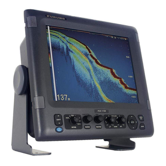
COLOR LCD SOUNDER FCV-1150
SAFETY INSTRUCTIONS ............................................................................ i
SYSTEM CONFIGURATION ...................................................................... iii
EQUIPMENT LISTS.................................................................................... iv
1. MOUNTING ............................................................................................ 1
1.1
Display Unit ..................................................................................................................1
1.2
Transducer ...................................................................................................................1
1.3
Water Temperature/Speed Sensor ..............................................................................2
2. WIRING .................................................................................................. 5
2.1
Interconnection .............................................................................................................5
2.2
Wiring Standard Equipment..........................................................................................6
2.3
Input/Output Sentences................................................................................................8
3. INITIAL SETTING ................................................................................ 10
3.1
Language Setting .......................................................................................................10
3.2
Transducer Data.........................................................................................................11
3.3
Speed/Water Temperature Sensor Calibration ..........................................................14
3.4
NMEA Port Setting .....................................................................................................16
3.5
Heaving Setting ..........................................................................................................17
APPENDIX TRANSDUCER 82B-35R .................................................AP-1
PACKING LIST ........................................................................................ A-1
OUTLINE DRAWINGS............................................................................. D-1
INTERCONNECTION DIAGRAM ............................................................ S-1
All brand and product names are trademarks, registered trademarks or service marks of their respective holders.
Installation Manual
www.furuno.com
Advertisement
Table of Contents

Related Manuals for Furuno FCV-1150


Summary of Contents for Furuno FCV-1150
-
Page 1: Table Of Contents
Installation Manual COLOR LCD SOUNDER FCV-1150 SAFETY INSTRUCTIONS ................i SYSTEM CONFIGURATION ..............iii EQUIPMENT LISTS..................iv 1. MOUNTING .................... 1 Display Unit ........................1 Transducer ........................1 Water Temperature/Speed Sensor ................2 2. WIRING ....................5 Interconnection ......................5 Wiring Standard Equipment..................6 Input/Output Sentences....................8 3. -
Page 3: Safety Instructions
Water leakage can sink the vessel. Also, confirm that the transducer will not loosen by ship's vibration. The installer of the equipment is solely responsible for the proper installation of the equipment. FURUNO will assume no responsibility for any damage associated with improper installation. - Page 4 CAUTION CAUTION Ground the equipment to The transducer cable must he handled prevent mutual interference. carefully, following the guidelines below. • Keep fuels and oils away from the Observe the following compass safe cable. distances to prevent interference to a •...
-
Page 5: System Configuration
SYSTEM CONFIGURATION Display unit CV-1150 NavNet 3D Navigator 12-24 VDC Satellite compass Rectifier PR-62 100/110/115/ 220/230 VAC 1 , 50/60 Hz Temperature sensor T-02MSB, etc. Speed/temp sensor ST-02MSB, etc. High Transducer Transducer : Standard supply : Optional supply : Local supply, External device... -
Page 6: Equipment Lists
EQUIPMENT LISTS Standard supply Name Type Code No. Remarks Display Unit CV-1150 Spare Parts SP02-05401 001-032-550 1 set See back of this manual. Accessories FP02-05700 000-011-976 1 set Installation Materials CP02-08301 001-032-560 1 set Option Name Type Code No. Remarks Transducer See next pages. - Page 7 Combination of transducer, thru-hull pipe and tank Output Frequency Ship type Transducer Thru-hull pipe Tank (kHz) 1k/1k 28/50 Steel 28F-8 TWB-6000(2) T-656 50B-9B 28/88 Steel 28F-8 TWB-6000(2) T-657 88B-8 50/88 Steel 50B-9B TWB-6000(2) T-658 88B-8 50/200 Steel 50/200-1T TFB-5000(1) T-603 50/200-1ST T-603F 1k/2k...
- Page 8 Output Frequency Ship type Transducer Thru-hull pipe Tank (kHz) 2k/3k 28/150 Steel 28F-18 TFB-7000(2) T-637 150B-12H TRB-1100(2) T-637-F 50/107 Steel 50B-12 TFB-7000(2) T-643 100B-10R TRB-1100(2) T-643-F 50/150 Steel 50B-12 TFB-7000(2) T-644 150B-12R TRB-1100(2) T-644-F 3k/2k 68/200 Steel 68F-30H TFB-7000(2) T-647 200B-8/8B TRB-1100(2) T-647-F...
- Page 9 Output Frequency Ship type Transducer Thru-hull pipe Tank (kHz) 3k/3k 38/150 Steel 38BL-15HR TFB-7000(2) T-683 150B-12H TRB-1100(2) T-683-F 38/200 Steel 38BL-15HR TFB-7000(2) T-683 200B-12H TRB-1100(2) T-683-F 50/88 Steel 50BL-24H TFB-7000(2) T-697 88F-126H TRB-1100(2) T-697-F Steel 50BL-24HR TFB-7000(2) T-682 88F-126H TRB-1100(2) T-682-F Steel 50F-24H...
- Page 10 Output Frequency Ship type Transducer Thru-hull pipe Tank (kHz) Steel 28F-18 TFB-5000(1) T-612 TRB-1000(1) T-612-F Steel 28BL-6HR TFB-5000(1) T-702 TRB-1000(1) T-702-F Steel 38BL-9HR TFB-5000(1) T-702 TRB-1000(1) T-702-F Steel 50B-12 TFB-5000(1) T-611 TRB-1000(1) T-611-F Steel 50BL-12 TFB-5000(1) T-702 TRB-1000(1) T-702-F Steel 50BL-12HR TFB-5000(1) T-702...
-
Page 11: Mounting
1. MOUNTING NOTICE Do not apply paint, anti-corrosive sealant or contact spray to coating or plastic parts of the equipment. Those items contain organic solvents that can damage coating and plastic parts, especially plastic connectors. Display Unit WARNING Turn off the power at the switchboard before beginning the installation. -
Page 12: Water Temperature/Speed Sensor
Water Temperature/ Speed Sensor Transom mount water temperature sensor T-02MTB • Fix the cable at a convenient location on the transom with the cable clamp. • When the cable is led through the transom board, make a hole of approx. 17 mm in diameter to pass the connector. - Page 13 Thru-hull mount water temperature sensor T-02MSB, T-03MSB Select a suitable mounting location considering the following points: • Select a mid boat flat position. The sensor does not have to be installed perfectly perpendicu- lar; however, the location should not be such that the transducer may be damaged when the boat is dry-docked.
- Page 14 Through-hull mount water temperature/speed sensor ST-02MSB, ST02-PSB Select a suitable mounting location considering the following: • Select a mid-boat flat position. The sensor does not have to be installed perfectly perpendicu- lar. The sensor must not be located where it might get damaged in dry-docking operation. •...
-
Page 15: Wiring
*: This unit cannot accept transducers of : Standard supply 53 to 65 kHz, 111 to 139 kHz and 171 to 183 kHz. : Option : Local supply, External device Wiring diagram for FCV-1150... -
Page 16: Wiring Standard Equipment
Note: Never connect the shield to #2 of [Composite transducer] the WAGO connector. BLK, RED: L side BLU, GRN: H side Fabrication of transducer cable Note: FCV-1150 cannot accept the transducers of 53 - 65 kHz, 111 to 139 kHz and 171 - 183 kHz. - Page 17 GPS receiver GP-310B and smart sensor). One connects to NMEA port J2 #1 to #2 and the other connects to the NMEA port J2 #3 to #4. A satellite compass can be connected to NMEA port J2 #5 to #6. Cable connected to NMEA port: Furuno cable MJ series Approx. 30 Shield Cut shield here and Clamp vinyl sheath with cable clamp.
-
Page 18: Input/Output Sentences
WAGO connector (for transducer and NMEA port) Press Opener (attached inner side of shield cover). 1. Twist conductors 2. Insert opener and press it down. 3. Insert core to hole. Twist. 4. Release opener. Core 5. Pull the core to confirm to make sure it is tightly fastened. - Page 19 Output sentences Sentence Data Remarks Depth below transducer Ver. 1.5 Depth below transducer and offset Ver. 2.0 With connection of water Water temperature temperature sensor Marker line position Ver. 2.0 SDmrk Mark position (L&L) and its additional data Speed thru water Navigation information Data of specified attribute (device name) Depth below sea surface...
-
Page 20: Initial Setting
3. INITIAL SETTING This chapter provides the information necessary for initial setup of the equipment. First turn on the power and set display language. Then, set transducer used, by model number (FURUNO trans- ducer only) or by specifications. Language Setting 1. -
Page 21: Transducer Data
Set the transducer model number properly. Wrong transducer setting can damage the transducer and void the warranty. Entering transducer data by transducer model The following table shows the transducers programmed in the FCV-1150. Type Output (kW) Type Output (kW) 28F-8... - Page 22 Note: The “XDCR Setting” dialog box (see the illustration that follows step 1 below) only appears when turning on the power after installation, after setting the desired language and the units of measurement (see section 3.1). To open the “XDCR Setting” dialog box after completion of the transducer setting, turn off the power, then turn on the power while pressing any key.
- Page 23 10.To connect to the NavNet 3D system, press to select “NavNet Mode” and then press the ENTER key. Select “On” and press the ENTER key. The following program versions can be connected to the FCV-1150. MFD8/12: 1950055-02.01 and later MFDBB: 1950064-02.01 and later 11.Press and hold down the [...
-
Page 24: Speed/Water Temperature Sensor Calibration
Note: The transducers of 53 - 65 kHz, 111 to 139 kHz and 171 - 183 kHz cannot be connected to the FCV-1150 because of noise. 1. At the XDCR Setting dialog box, select “XDCR Select” and press the ENTER key. - Page 25 3. Press to select "Temp" and then press the ENTER key. Temperature calibration screen 4. Press to set the value for the temperature calibration and then press the ENTER key. For example, if the temperature indication is 2.5°C higher than the actual value, set “-2.5°C”.
-
Page 26: Nmea Port Setting
• In/In: NMEA port J2 #1 & #2 changes to input port. (Available with connection of the GP-310B/ 320B and a wind sensor.) NMEA Output: Set the output data sentences. • Off: Outputs the "output data sentences" (see page 9). • On: Outputs the "output data sentences" of FCV-1150 and sentences which are input from other equipment. -
Page 27: Heaving Setting
TLL Output: Output the position specified by the MARK key to the plotter connected. • Off: Does not output latitude/longitude. • TLL: Outputs latitude/longitude. • FURUNO-TLL: Outputs latitude/longitude, depth and water temperature. This requires FURUNO-TLL enabled device. Port Monitor: Port Monitor provides information for the data sentences input from the NMEA port. - Page 28 7. Press to select “Stabi. Area“ and then press the ENTER key. 8. Press to select desired Stabi. Area and then press the ENTER key. When heaving exceeds the value set here, stabilization is stopped and the stabilizer icon at the top of the screen disappears. However, the heaving mode is kept “On“. When heaving is once again less than the value set here, stabilization is restarted and the stabilizer icon reappears.
-
Page 29: Appendix Transducer 82B-35R
APPENDIX TRANSDUCER 82B-35R The 82B-35R is a transducer with wide bandwidth of 65 kHz-110 kHz. It is constructed to provide protection against slamming. Transducer, thru-hull pipe and tank list Frquency Transducer Hull Tank Fasten inside Fasten outside (kHz) Material (Code No.) hull (Code No.) hull (Code No.) 28/82... - Page 30 Setting for dual frequency transmitting 1. Set the XDCR SELECT menu as follows (see page 12 and 13). Setting for “HF” connection Setting for “LF” connection 2. Press the [PWR] key to turn the power off, and turn it on again. 3.
- Page 36 : +81-(0)798-65-4200 A : DEC 2007 Printed in Japan All rights reserved. D : NOV . 16, 2011 Pub. No. IME-23780-D *00016773313* *00016773313* (REFU ) FCV-1150 *00016773313* *00016773313* * 0 0 0 1 6 7 7 3 3 1 3 *...
Need help?
Do you have a question about the FCV-1150 and is the answer not in the manual?
Questions and answers