Table of Contents
Advertisement
Quick Links
Advertisement
Table of Contents

Related Manuals for Furuno Color LCD Sounder FCV-620/585


Summary of Contents for Furuno Color LCD Sounder FCV-620/585
- Page 2 • This manual is intended for use by native speakers of English. • FURUNO will assume no responsibility for the damage caused by improper use or modification of the equipment or claims of loss of profit by a third party.
- Page 3 NOTICE A warning label is attached to the equipment. Do not remove the label. If the label is missing or damaged, contact a FURUNO agent or dealer about replacement. WARNING Name: To avoid electrical shock, do not Warning Label (1) remove cover.
- Page 4 The installer of the equipment is solely responsible for the proper installation of the equipment. FURUNO will assume no responsibility for any damage associated with improper installation. Use the specified power cable.
-
Page 5: Table Of Contents
TABLE OF CONTENTS FOREWORD ... v SYSTEM CONFIGURATION ... vi EQUIPMENT LISTS... vii 1. OPERATION ... 1 1.1 Control Description... 1 1.2 Power On/Off ... 2 1.3 Adjusting Display Contrast and Brilliance... 2 1.4 Choosing a Display Mode ... 2 1.5 Choosing Range ... -
Page 6: Foreword
We are confident you will see why the FURUNO name has become synonymous with quality and reliability. For over 50 years FURUNO Electric Com- pany has enjoyed an enviable reputation for innovative and dependable marine elec- tronics equipment. This dedication to excel- lence is furthered by our extensive global network of agents and dealers. -
Page 7: System Configuration
SYSTEM CONFIGURATION FCV-620 DISPLAY UNIT CV-620 Transducer 520-5PSD, 520-5MSD, 525-5PWD, 525ST-MSD, 525ST-PWD FCV-585 DISPLAY UNIT CV-585 Matching Box MB-1100* Transducer 520-5PSD, 520-5MSD, 525-5PWD, 525ST-MSD, 525ST-PWD Power supply 12-24 VDC GPS Navigator Water temperature sensor Water temperature/speed sensor ST-02MSB, ST-02PSB Water temperature sensor T-02MSB, T-02MTB, T-03MSB Power supply 12-24 VDC... -
Page 8: Equipment Lists
EQUIPMENT LISTS Standard supply for FCV-620 Name Display Unit CV-620 520-5PSD Transducer 520-5MSD 525-5PWD Triducer (transducer 525ST-MSD plus spd/temp sensor) 525ST-PWD Installation Materials • Cable assy. (1 pc., KON-004-02M, 000-156-405, for power and data) (CP02-07900) • Self-tapping screw (4 pcs., 5x25 SUS304, 000-162-610-10) •... - Page 9 EQUIPMENT LISTS Name • Flush mounting sponge (1 pc., 02-155-1081-1, 100-330-851-10) • Wing nut (4 pcs., M4 SUS304, 000-863-331) • Flat washer (4 pcs., M4 SUS304, 000-864-126) Accessories • Spring washer (4 pcs., M4 SUS304, 000-864-256) (FP02-05601) • Threaded rod (4 pcs., M4x50 SUS304, 000-162-679-10) •...
-
Page 10: Operation
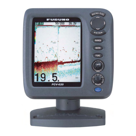
OPERATION Control Description Note: The FCV-620 and FCV-585 share the same features. For sake of brevity, this manual uses “FCV-620”. Control • Opens/closes menu. MENU/ESC • Escapes from current operation. • Moves cursor on the menu. • Adjusts settings. (TrackPad) •... -
Page 11: Power On/Off
1. OPERATION Power On/Off 1. Press the /BRILL key to turn on the power. The unit beeps, the startup screen appears, and then the equipment checks the ROM and RAM for proper operation. After the com- pletion of the equipment check, the last-used display appears. - Page 12 2. Rotate the MODE knob again to choose the display mode desired. The screen you chose appears soon there- after. Single frequency display Low frequency (50 kHz) The sounder uses ultrasonic signals to detect bottom conditions. The lower the frequency of the signal, the wider the detection area.
- Page 13 1. OPERATION Bottom zoom display This mode expands bottom and bottom fish on the left-half window. This mode is useful for determining bottom contour. When the bottom depth increases, the display automatically shifts to keep the bottom echo at the lower part of the screen.
-
Page 14: Choosing Range
Choosing Range The basic range may be chosen in Auto or Manual mode. 1. Press the RANGE key to open the range set- ting window. Range Auto Manual 15 ft 30 ft 60 ft These are 120 ft available with 200 ft Manual mode. -
Page 15: Measuring Depth
1. OPERATION Manual gain adjustment The GAIN knob adjusts the sensitivity of the receiver. Generally, use a higher gain setting for greater depths and a lower setting for shallower waters. CAUTION Use the proper gain setting. Incorrect gain may produce wrong depth indication, possibly resulting in a dangerous situation. -
Page 16: Shifting Range
the menu window (left) is displayed to gray. You may also use to move the cursor. 4. Use to choose the menu item desired and press the ENTER key. The selected setting box or window appears. Depth Size Small Medium Large [ENTER] : Set [MENU] : Cancel... -
Page 17: Suppressing Interference
1. OPERATION Sounder Pic. Advance : 1/1 Zoom Mode : Bottom Lock Shift Bottom Zone Interference : Auto Color Erase Clutter White Line White Marker : Medium Smoothing : On TX Power : Auto TX Rate : 10 Transducer* : 600W : Select [ENTER] : Enter... -
Page 18: Suppressing Low Level Noise
1.12 Suppressing Low Level Noise Low intensity "speckles" may appear over most of screen. This is mainly due to sediment in the water or noise. These can be suppressed by adjusting Clutter on the menu. Clutter appearance Note: Clutter cannot be adjusted when Fishing or Cruising is selected on the Auto Gain setting window. -
Page 19: A-Scope Display
1. OPERATION 1.14 A-Scope Display This display shows echoes at each transmission with amplitudes and tone proportional to their intensities, on the right of the screen. It is useful for estimating the kind of fish school and bottom composition. Note: In the dual frequency display, the A- Scope display is only available with the high fre- quency display. -
Page 20: Alarms
Note: To hide the fish symbol, choose Off at step 4 and press the ENTER key. 5. Press the MENU/ESC key twice to close the window. Fish Info 1. Press the MENU/ESC key to open the menu. 2. Use to choose Display and press the ENTER key. - Page 21 1. OPERATION tain distance from the bottom. Note that the bottom lock display must be turned on to use this alarm. Water temperature alarm: The water tempera- ture alarm alerts you when the water tempera- ture is within (inside alarm) the alarm range set or under/over (outside alarm) the range set.
-
Page 22: Func Key
8. Use to choose Span (or Radius for Arrival) and press the ENTER key. 9. Use to set the range of depth, tem- perature, speed or distance as appropriate. To shorten the alarm range marker use and to lengthen use 10.For the bottom alarm, temperature alarm, speed alarm or arrival alarm, press the ENTER key to finish, and then go to step 13. - Page 23 [ENTER] : Enter [MENU] : Quit Waypoint setting window Note1: When TLL or FURUNO-TLL is selected at TLL Output on the NMEA menu of the System menu, the latitude and longitude position at the cursor position is output to the navigator.
-
Page 24: Setting Up Nav Data Displays
1.18.2 Editing a registered waypoint 1. Press the MENU/ESC key to open the menu. 2. Use to choose Data and press the ENTER key. 3. Use to choose WPT List and press the ENTER key. 4. Use to choose a waypoint to be edited and press the ENTER key. -
Page 25: Menu Items
1. OPERATION XTE MARINA SPEED (SOG) PORT 0.20 27.3 WIND SPEED (STW) COMPASS WPT MARINA HEADING True SOG: Speed over STW: Speed relative Graphic displays DEPTH POSITION ° 23 45.6789 1234 ° 123 45.6789 COURSE True** SPEED (STW) ° 12.3 123.4 TRIP METER ODOMETER... - Page 26 Bottom Zone Above Below Border (above) Bottom zone Border (below) The sea-bed surface is shown only in the predefined area. [ENTER] : Set [MENU] : Cancel Bottom Zone setting window 2. Use to choose the border desired (Above or Below). 3.
- Page 27 1. OPERATION Display menu Display A-Scope : Off Depth Size : Small Zoom Marker : Off Temp Graph : Off Window Size Battery : Off Color Bar : On Palette : White Colors : 64 Header Info : On Nav Data1 Nav Data2 Fish Info : Off...
- Page 28 Data menu This menu mainly sets up how to display data input by external equipment. Data Go to WPT : Off WPT List Data Box 1 : Off Data Box 2 : Off Bearing : True Wind Spd/Dir : True Trip Source : Own Temp Source...
-
Page 29: System Menu
SYSTEM MENU Displaying System Sub Menu The System menu mainly consists of items which once set do not require frequent adjust- ment. This menu has nine sub menus. To dis- play each sub menu, do the followings. 1. Press the MENU/ESC key to open the menu. -
Page 30: Units Menu
Japanese. To change language, select lan- guage desired and press the ENTER key. Units Menu Units Depth : ft : °F Temp Fish Size : inch Speed : kt Wind : kt Distance : nm : Select [ENTER] : Enter [MENU] : Back Units menu... -
Page 31: Maintenance, Trouble- Shooting
MAINTENANCE, TROUBLE- SHOOTING WARNING ELECTRICAL SHOCK HAZARD Do not open the equipment. Only qualified personnel should work inside the equipment. Maintenance Regular maintenance is essential for good performance. Checking the items listed in the table below monthly will help keep your equip- ment in good shape for years to come. -
Page 32: Troubleshooting
Troubleshooting The table below provides basic trouble- shooting procedures which the user may follow to restore normal operation. Troubleshooting table If... then check... neither echo nor • battery voltage. fixed range scale • fuse. appears • power supply. • power cable. no echo appears •... -
Page 33: Test Pattern
3. MAINTENANCE, TROUBLESHOOTING Checking GAIN knob: Rotate the knob. The indication goes higher with clockwise rotation; lower with counterclockwise rota- tion. Press the knob. The knob corre- sponding on-screen circle "lights" in red if the knob is normal. Checking MODE knob: Rotate the knob, and corresponding on-screen circle "lights"... -
Page 34: Installation
INSTALLATION Display Unit Mounting considerations The display unit can be installed on a tabletop or flush mounted in a panel. When choosing a location keep the following in mind: • The temperature and humidity should be moderate and stable. • Locate the unit away from exhaust pipes and vents. -
Page 35: Thru-Hull Mount Transducer
4. INSTALLATION Thru-hull Mount Transducer Transducer mounting location The thru-hull mount transducer (520-5PSD, 520-5MSD) provides the best performance of all, since the transducer protrudes from the hull and the effect of air bubbles and turbu- lence near the hull skin is reduced. When the boat has a keel, the transducer should be at least 30 cm away from it. - Page 36 Typical thru-hull mount transducer installations Flat Washer Fairing Block Hull Deep-V Hull Flat Washer Hull Rubber Washer Flat Hull Typical thru-hull mount transducer installations Procedure for installing the thru-hull mount transducer 1. With the boat hauled out of the water, mark the location chosen for mounting the trans- ducer on the bottom of the hull.
-
Page 37: Transom Mount Transducer
4. INSTALLATION Transom Mount Transducer The transom mount transducer is very com- monly employed, usually on relatively small I/ O or outboard boats. Do not use this method on an inboard motor boat because turbulence is created by the propeller ahead of the trans- ducer. - Page 38 Remarks on installation • Turn off the engine and anchor the boat while installing the equipment. • Install the transducer in the engine room. • Except for installing the transducer to the bottom of hull, do not turn on its power so it may be damaged.
-
Page 39: Triducer
4. INSTALLATION b)Gently dismount the transducer with a knife or a piece of wood. c)Reattach the transducer elsewhere as shown in "Attaching the transducer." d)Check the installation again. Final preparation Support the transducer with a piece of wood to keep it in place while it is drying. Let the transducer dry 24-72 hours. - Page 40 Note 3: For single drive boat, mount on the starboard side at least 75 mm (3") beyond the swing radius of the propeller. 75 mm (3") minimum beyond swing radius Mounting location on single drive boat Note 4: For twin drive boat, mount between the drives.
- Page 41 4. INSTALLATION 3. If the bracket has been temporarily fas- tened to the transom, remove it. Apply a marine sealant to the threads of the three #10 x 1-1/4" self tapping screws to prevent water seeping into the transom. Screw the bracket to the hull.
-
Page 42: Optional Water Temperature/Speed Sensor
8. Position the two cable clamps and fasten them in place. If used, push the cable cover over the cable and screw it in place. 9. Route the cable to the instrument being careful not to tear the cable jacket when passing it though the bulkhead(s) and other parts of the boat. -
Page 43: Wiring
4. INSTALLATION Thru-hull mount water temperature sensor T-02MSB, T-03MSB • Select a suitable mounting location consid- ering the following points: • Select a mid boat flat position. The sensor does not have to be installed perfectly per- pendicular; however, the location should not be such that the transducer may be damaged when the boat is dry-docked. -
Page 44: Power Connector
Fuse holder Power supply lines (red and black) Cable tie How to fix fuse holders Establishing the ground The ground wire (1.25 sq or more, local supply) should be as short as possible. The signal line ground is isolated from the chassis ground, however the power line is not insu- lated. -
Page 45: Iec 61162-1 Data Sentences
4. INSTALLATION Matching box MB-1100 Part Type Code No. Matching MB-1100 000-041-000 Box* Crimp-on FV1.25-3, 000-538-113 Cord Lock** NC-1 000-516-650 *: With 10P connector cable **: For connecting two transducers Fabricating the transducer cable Fabricate the transducer cable as below and connect it to the matching box. -
Page 46: Adjustments After Installation
TLL Output Output the position specified by MARK key to the plotter connected. Off: Does not output latitude/longitude. TLL: Outputs latitude/longitude. FURUNO-TLL: Outputs latitude/longitude, depth and water temperature. Required FURUNO-TLL enabled device. Port Monitor Port Monitor provides information for the data sentences input to the 12-24 VDC/NMEA port. -
Page 47: Menu Tree
MENU TREE Sounder MENU key Display Alarm Pic. Advance (4/1, 2/1, 1/1 , 1/2, 1/4, 1/8, 1/16, Stop) Zoom Mode ( Bottom Lock , Bottom Zoom, Marker Zoom) Shift (0 - 2500 ft, 0 ft ) Bottom Zone Interference (Off, Low, Medium, High, Auto ) Color Erase (0 - 50 %, 0 % ) Clutter (0 - 100 %, 0 % ) White Line (0 - 50 %, 0 % ) - Page 48 NMEA Port ( In/Out , In/In) NMEA Output ( Off , On) WAAS Setup ( Off , WAAS-00 - WAAS-27) TLL Output (Off, TLL , FURUNO-TLL) Port Monitor Draft (-15.0 - +50.0 ft, +0.0 ft ) Gain ADJ 200 (-20 - +20, +0 ) Gain ADJ 50 (-20 - +20, +0 ) Temp (-20.0 - +20.0 °F, +0.0 °...
-
Page 49: Specifications
SPECIFICATIONS OF ECHO SOUNDER GENERAL TX Frequency Transmit Method Output Power FCV-620 FCV-585 TX Rate Pulse-length Sensitivity DISPLAY UNIT Display System FCV-620 FCV-585 Display Mode Expansion Mode Basic Range Unit Range Shift Zoom Range Display Advance Speed 8 steps (Lines/TX; 4/1, 2/1, 1/1, 1/2, 1/4, 1/8, 1/16, Freeze) Function Settings Display Color FCV-620/585... - Page 50 3. INTERFACE Input Data Sentences Output Data Sentences IEC61162-1 (NMEA0183 Ver 1.5/2.0/3.0), interval: 2 s 4. POWER SUPPLY FCV-620 FCV-585 5. ENVIRONMENTAL CONDITION Ambient Temperature Relative Humidity Waterproofing and Dust Proofing (IEC60529) Vibration 6. CHASSIS COLOR Display Unit IEC61162-1 (NMEA0183 Ver 1.5/2.0/3.0) Order of priority Latitude/Longitude: GGA>RMC>RMA>GLL Course (true): VTG>RMC>RMA...
- Page 51 DN: cn=Hatai, c=JP - 日本, o=Seigi, ou=Joho, 電子署名者 : Hatai 日付 : 2006.03.02 11:23:20 +09'00'...
- Page 52 Hatai 電子署名者 : Hatai DN: cn=Hatai, c=JP - 日本, o=Seigi, ou=Joho, email=yoshitoshi.hatai@furuno.co.jp 日付 : 2006.03.09 17:17:27 +09'00'...
- Page 54 XDR-P XDR-SHIELD XDR-M TEMP0V MJ-A10SRMD TEMP SPD0V/ST-SHIELD 12V-P1 MJ-A10SPF 02S4147,0.2m MJ-A6SRMD XDR-P XDR-SHIELD XDR-M 8m,φ5.4 TEMP0V TEMP SPD0V/ST-SHIELD 12V-P1 10m,φ5.4 MJ-A10SPF XDR-P XDR-SHIELD XDR-M MJ-A10SPF アカ 10m,φ12 クロ アカ クロ 10m,φ12 クロ ミドリ アオ アカ 10m,φ12...
- Page 56 (title and/or number and date of issue of the standard(s) or other normative document(s)) For assessment, see • EMC Test Report FLI 12-05-053 of 14 November 2005 prepared by Furuno Labotech International Co., Ltd. This declaration is issued according to the Council Directive of 3 May 1989 on the approximation of the laws of the Member States relating to electromagnetic compatibility (89/336/EEC).
Need help?
Do you have a question about the Color LCD Sounder FCV-620/585 and is the answer not in the manual?
Questions and answers