Table of Contents
Advertisement
Quick Links
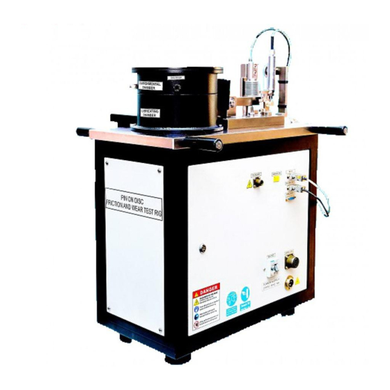
Pin On Disc Friction & Wear Test Rig
K93500 / K93590
Pin On Disc Machine
Operation and Instruction Manual
REV A
Koehler Instrument Company, Inc.
1595 Sycamore Avenue • Bohemia, New York 11716-1796 • USA
Toll Free: 1-800-878-9070 (US only) • Tel: +1 631 589 3800 • Fax: +1 631 589 3815
http://www.koehlerinstrument.com • e-mail: info@koehlerinstrument.com
Petroleum Testing & Analysis Instrumentation • Custom Design & Manufacturing
Page 1
Advertisement
Table of Contents

Related Manuals for Koehler K93500


Summary of Contents for Koehler K93500
- Page 1 Pin On Disc Friction & Wear Test Rig K93500 / K93590 Pin On Disc Machine Operation and Instruction Manual REV A Koehler Instrument Company, Inc. 1595 Sycamore Avenue • Bohemia, New York 11716-1796 • USA Toll Free: 1-800-878-9070 (US only) • Tel: +1 631 589 3800 • Fax: +1 631 589 3815 http://www.koehlerinstrument.com •...
- Page 2 Pin On Disc Friction & Wear Test Rig Page 2...
-
Page 3: Table Of Contents
Pin On Disc Friction & Wear Test Rig CONTENTS PART I GENERAL INFORMATION PART II DESCRIPTION PART III INSTALLATION PART IV OPERATION PART V MAINTENANCE PART VI CALIBRATION PART VII CIRCUIT DIAGRAM PART VIII BROUGHT OUT ITEMS LIST PART IX TROUBLE SHOOTING PART X SOFTWARE INSTALLATION GUIDE... -
Page 4: Part I
Pin On Disc Friction & Wear Test Rig PART I GENERAL INFORMATION WARRANTY The equipment is under warranty for a period of 12 months from the date of supply against manufacturing defects only. The damages occur due to improper use, power fluctuation etc., are not covered under this warranty. - Page 5 Pin On Disc Friction & Wear Test Rig SAFETY PRECAUTIONS The Pin on Disc Friction & Wear Test Rig is an electro-mechanical Device. Please follow the instructions carefully. Personnel injury may be resulted by improper operation. The equipment may be damage by improper operation. ...
-
Page 6: Description
Pin On Disc Friction & Wear Test Rig PART II DESCRIPTION The Pin on Disc Friction & Wear Test Rig is intended for determination of tribological properties of different materials. Ascertain the validity of law’s of friction (ii) Wear characteristics of the given specimen (iii) Determination of wear constant (iv) - Page 7 Pin On Disc Friction & Wear Test Rig Spindle AC Drive Step down transformer AC Motor 230V to 110V Fig.,No.,02 Environmental Chamber Lubricating Re circulating Chamber Fig.,No.,03 Page 7...
- Page 8 Pin On Disc Friction & Wear Test Rig Loading Lever Loading Pan Dead Weights Fig.,No.,04 Load up to 20 Kg can be applied on the specimen through loading lever arrangement, which consists of loading pan and dead weights. Page 8...
- Page 9 Pin On Disc Friction & Wear Test Rig 9 Pin ‘D’ Type Connector for LVDT 2 Pin allied connector for heater 9 Pin ‘D’ Type Connector for Load cell 2 Pin ‘K’ Type Thermocouple 19 Pin M.S.Connector connector 15 Pin ‘D’ Type Signal Resistance Control Output Connector Circuit Breaker (RCCB)
- Page 10 Pin On Disc Friction & Wear Test Rig Technical specifications of PIN ON DISC FRICTION & WEAR TEST RIG: Normal Load Range Up to 200N Frictional Force Range Up to 200N with a resolution of 1 N with tare facility Wear Measurement Range ±...
- Page 11 Pin On Disc Friction & Wear Test Rig PIN DISC FRICTION & WEAR TEST RIG -CONTROLLER Test parameters such as wear, frictional force, test speed, test duration and pin temperature can be read with the front panel of the controller box. The wear, frictional force and temperature of the specimen are continuously displayed.
- Page 12 Pin On Disc Friction & Wear Test Rig Back Panel of Controller MS Connector FUSE Data Acquisition Cable Signal Input Connector Fig. No.07 Data acquisition cable one end is fitted with the NI USB 6008 A-D card, other end has to be connected to PC, which sends signals received from Sensors to PC.
- Page 13 Pin On Disc Friction & Wear Test Rig POWER INPUT CABLE (Fig.No.08) It is a 3-core cable with 4 pin harting connector end to supply 110V input supply to machine. CONTROL CABLE (Fig.No.09) It is a 19 pin MS connector cable which carries power from the controller to machine panel. SIGNAL CABLE (Fig.No.10) This connects machine front panel to controller back panel, it sends the signals of frictional force and LVDT sensor to controller.
- Page 14 Pin On Disc Friction & Wear Test Rig DATA ACQUISTION SYSTEM INCLUDES. a) Data acquisition cable fixed with controller (USB Cable) DATA ACQUISITION SYSTEM Fig.No.11 Data Acquisition and Data Processing. Analog data is converted into digital and processed in the NI data card. It is logged to ...
-
Page 15: Installation
Pin On Disc Friction & Wear Test Rig PART III INSTALLATION Remove the top panel of controller and visually inspect for any damage. Place controller box on a table connect it to machine through control cable, power cable and signal input cable. -
Page 16: Operation
Pin On Disc Friction & Wear Test Rig PART IV OPERATION The operation of PIN ON DISC FRICTION & WEAR TEST RIG is made simple and user friendly by providing controls and displays on the front panel of the control box. The controls for operation are: Wear (displacement)- to be preset to zero before start of operation... - Page 17 Pin On Disc Friction & Wear Test Rig SPECIMEN FIXING DETAILS: Specimen height adjustment knob Specimen holder plate Lock nut Specimen holder Specimen Fixed jaw Adjustable Clamping screws Fig.No.12 Assembly of specimen holding unit Fig.No.13 & 14 Specimen holding unit to fix the loading lever assembly Fix the specimen holding unit to loading lever assembly Fig.
- Page 18 Pin On Disc Friction & Wear Test Rig Height adjustment block is given to ensure that the loading arm is parallel to the plane of the wear disc. Tighten the clamping screws on the adjustable jaw to hold the specimen pin firmly.
- Page 19 Pin On Disc Friction & Wear Test Rig Slider Assembly Clamping Nuts Scale (track radius in mm) Fig. No.18 Set required track radius by adjusting the traverse of the scale-slider assembly. Tighten the slider clamping nuts and ensure assembly is clamped firmly. Keep the required dead weights on the loading pan.
- Page 20 Pin On Disc Friction & Wear Test Rig Select the mode of operation (Time) by actuating MD selection switch. Enter the required data of Timer of the test using arrow buttons to change the hour, minute and MD soft button to set the time. Data entry takes place from the last digits i.e.
- Page 21 Pin On Disc Friction & Wear Test Rig LUBRICATING RE-CIRCULATING SYSTEM Tank Capacity – 3 Litres, , flow rate can be adjusted with the flow control valve min 10ml/min – 1 ltr/min. Viscosity Range – 90 SAE Max., Temperature – Ambient to 60 C Max.
- Page 22 Pin On Disc Friction & Wear Test Rig Knob for outlet Oil outlet nozzle nozzle distance adjustment Fig No. 22 Page 22...
- Page 23 Pin On Disc Friction & Wear Test Rig ENVIRONMENTAL CHAMBER WITH VIEW PORT The main objective is the pin on disc wear and friction test rig with an environmental chamber under inert gaseous atmosphere to study the friction and co-efficient of friction and wear & environmental chamber maintains a positive pressure of desired inert gases.
-
Page 24: Maintenance
Pin On Disc Friction & Wear Test Rig PART V MAINTENANCE Ensure connectors are secured tight. Loose contacts cause erratic functioning and error in readings. While not in use, the machine is to be fully covered to keep it free from dust. ... -
Page 25: Calibration
Pin On Disc Friction & Wear Test Rig PART VI CALIBRATION Frictional Force Calibration Fixture Fig No. 25 This procedure is to be followed once in six months and in case of replacement of sensor or display module, Page 25... - Page 26 Pin On Disc Friction & Wear Test Rig WEAR Place the leveling block under the loading arm. Loosen the lock screw. Move up the LVDT plunger by adjusting the thumbnut to display “Zero”. Lock the LVDT position by tightening the lock screw. Make the wear display “Zero” through ‘the data acquisition software’.
- Page 27 Pin On Disc Friction & Wear Test Rig FRICTIONAL FORCE Mount the loading pan on the calibration fixture. Suspend a loading pan to the load cell sensing head. Put 1 KG weight on the pan and observe the frictional force display on the controller front panel.
-
Page 28: Circuit Diagram
Pin On Disc Friction & Wear Test Rig PART VII CIRCUIT DIAGRAM Page 28... -
Page 29: Brought Out Items List
Pin On Disc Friction & Wear Test Rig PART VIII BROUGHT OUT ITEMS LIST ITEM NAME MODEL\PART NUMBER SPECIFICATIONS QUANTITY Line Filter Delta Electronics 240VAC,16A 20DBAG5 Glass Fuse with Protectron 10 A holder Rotary Switch L&T Salzer-AC121A-690 3 Pole ,16A Push button Elcom 16dia 1NO+1NC Contact... - Page 30 Pin On Disc Friction & Wear Test Rig Autonics MT4W 100-240VAC 50/60 HZ Indicator 0-2500 RPM SMPS BTH Mini Input-230VAC,2.5A Output-12VDC,1A Control Circuit Local Make IC-ULN2003 Card Resistor-2.2KΩ Cartridge Nex Thermal 2×200w Heater Emergency Elcom 1NC contact Switch Thermocouple R.tech K-Type Thermocouple 0-300°C Relay Base...
-
Page 31: Trouble Shooting
Pin On Disc Friction & Wear Test Rig PART IX TROUBLE SHOOTING Symptoms TROUBLESHOOTING METHODS REMARKS Motor not running 1. Ensure Ac Drive is ON 1. Power on 2. Check for RPM Potentiometer 2. Turn the knob to max 3. Check for cycle start pushbutton 3. - Page 32 Pin On Disc Friction & Wear Test Rig Insert the DVD into the drive, Copy the folder Pin On Disc Tester to D:\ drive .The software will not work if D:\ is not present in such case please allocate D:\ letter path Install the Software while in D:\ drive, click on Pin On Disc Tester Folder.
- Page 33 Pin On Disc Friction & Wear Test Rig Now click on Installer Folder and click on setup. Page 33...
- Page 34 Pin On Disc Friction & Wear Test Rig By default the installation directory will be C:\ drive. Page 34...
- Page 35 Pin On Disc Friction & Wear Test Rig Following setup screen will appear. Page 35...
- Page 36 Pin On Disc Friction & Wear Test Rig Click next to Continue Page 36...
- Page 37 Pin On Disc Friction & Wear Test Rig This screen will highlight components to be installed and click next. Page 37...
- Page 38 Pin On Disc Friction & Wear Test Rig Wait for installation to complete. Page 38...
- Page 39 Pin On Disc Friction & Wear Test Rig Click finish and restart the computer. Then plug in the data acquisition cable to USB port, the device driver will be automatically installs After completion- go to start menu>all program>Pin on Disc Friction and Wear Test Rig>Pin On Disc Test-Create Shortcut to Desktop Click on the Pin on Disc Tester icon to open the software.
- Page 40 Pin On Disc Friction & Wear Test Rig Front panel of the Software. Please Note: First open the software then switch on the controller power Page 40...
- Page 41 Pin On Disc Friction & Wear Test Rig The software consists of following modes Diagnostic Mode In this mode the user can check the interface between the PC and the machine. This mode is used for calibration purpose also, to bring the LVDT sensor to zero position (refer the user manual). Page 41...
- Page 42 Pin On Disc Friction & Wear Test Rig Test Parameter Mode In this mode user should enter the parameter values before starting the test and click save file button. Page 42...
- Page 43 Pin On Disc Friction & Wear Test Rig Test Analysis Mode In this mode the user can analysis test results and compare five different such files in one plot. Page 43...
- Page 44 Pin On Disc Friction & Wear Test Rig Auto Test Mode In this mode user can call the save file that was created in test parameter mode and press cycle start button in controller to begin the test. Page 44...
- Page 45 Pin On Disc Friction & Wear Test Rig How to start the test Click on Diagnostic mode Page 45...
- Page 46 Pin On Disc Friction & Wear Test Rig Ensure the LVDT voltage reading is made nearest zero ex: 0.05v (refer user manual) and user tare button Ensure Frictional force value to zero by Tare button as well and click main menu. Page 46...
- Page 47 Pin On Disc Friction & Wear Test Rig Now click on Test parameter Page 47...
- Page 48 Pin On Disc Friction & Wear Test Rig Enter all parameter such as Test name, Normal load applied, Test Duration, Sampling Time, avg Time, Test Rpm ,Pin Dia, Track Radius and specimen type and click save file . Sliding Distance in meters is automatically calculated by the software when user click save file button. Page 48...
- Page 49 Pin On Disc Friction & Wear Test Rig User can also recall the previously saved file by click edit/read file button and change the name or parameters accordingly and click save file button. Click on main menu . Page 49...
- Page 50 Pin On Disc Friction & Wear Test Rig Page 50...
- Page 51 Pin On Disc Friction & Wear Test Rig When user clicks on Auto mode a dialog box will appear select the desired file name to run the test. Page 51...
- Page 52 Pin On Disc Friction & Wear Test Rig The test parameters is shown on right side Ok then press cycle start button on the controller to begin the test. The following such screen is shown below. Few tests conducted By Magnum Engineers Page 52...
- Page 53 Pin On Disc Friction & Wear Test Rig User can click on online view button to enable single or multiple plot views Page 53...
- Page 54 Pin On Disc Friction & Wear Test Rig Test Completion Reports on materials Page 54...
- Page 55 Pin On Disc Friction & Wear Test Rig Test Duration: 30mins Specimen: Mild Steel Page 55...
- Page 56 Pin On Disc Friction & Wear Test Rig Test Duration : 30min Specimen : Teflon Page 56...
- Page 57 Pin On Disc Friction & Wear Test Rig Test Duration : 30min. Specimen : Aluminum Page 57...
Need help?
Do you have a question about the K93500 and is the answer not in the manual?
Questions and answers