Table of Contents
Advertisement
Quick Links
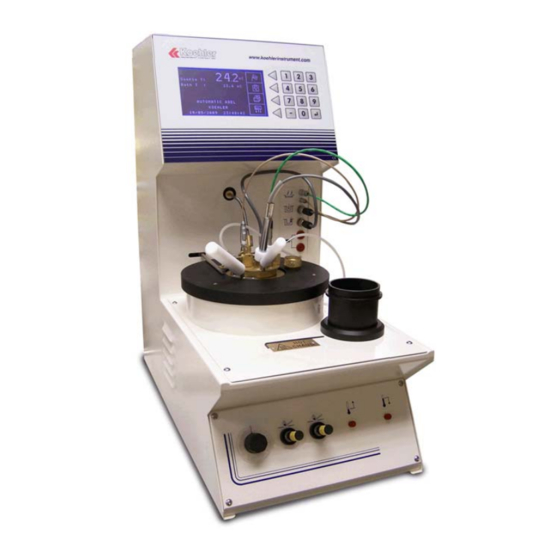
K877XX
Automatic Tag Closed Cup Flash Point
Tester
Operation and Instruction Manual
Koehler Instrument Company, Inc.
1595 Sycamore Avenue • Bohemia, New York 11716-1796 • USA
Toll Free: 1-800-878-9070 (US only) • Tel: +1 631 589 3800 • Fax: +1 631 589 3815
http://www.koehlerinstrument.com • e-mail: info@koehlerinstrument.com
Petroleum Testing & Analysis Instrumentation • Custom Design & Manufacturing
Advertisement
Table of Contents

Subscribe to Our Youtube Channel
Related Manuals for Koehler K877 Series


Summary of Contents for Koehler K877 Series
- Page 1 Automatic Tag Closed Cup Flash Point Tester Operation and Instruction Manual Koehler Instrument Company, Inc. 1595 Sycamore Avenue • Bohemia, New York 11716-1796 • USA Toll Free: 1-800-878-9070 (US only) • Tel: +1 631 589 3800 • Fax: +1 631 589 3815 http://www.koehlerinstrument.com •...
-
Page 2: Table Of Contents
CONTENTS CONTENTS........................... 2 I - GENERAL..........................4 - 1.1 – VERIFICATION AFTER TRANSPORT................4 - 1.2 – SAFETY INSTRUCTIONS ....................4 - 1.3 – IDENTIFICATION OF THE EQUIPMENT................ 4 - 1.4 – INSTRUCTIONS FOR USE..................... 5 - 1.5 – INSTALLATION INSTRUCTIONS .................. 5 II –... - Page 3 - 8.6 – PRINTING OUT OF LOG................... 27 IX – SAFETY DEVICES......................28 - 9.1 – SAFETY DEVICE - ABSENCE OF SAMPLE PROBE ..........28 - 9.2 – NO INCREASE IN SAMPLE PROBE TEMPERATURE..........28 - 9.3 – ELECTRICAL SAFETY DEVICE ................28 - 9.4 - SAMPLE TEMPERATURE SAFETY DEVICE............
-
Page 4: I - General
I – GENERAL - 1.1 – VERIFICATION AFTER TRANSPORT Check the condition of the packaging and make any reservations to the transport operator in the event of any damage. Compare the contents (accessories) with the list supplied. Check the condition of the accessories. - 1.2 –... -
Page 5: Instructions For Use
- 1.4 – INSTRUCTIONS FOR USE The equipment must be used solely: Using the methods indicated in the instructions. Using the accessories supplied and indicated in the instructions. In accordance with the test and start up procedures described in the instructions. - Page 6 The gas circuit of the equipment can be connected to mains gas of 50 mbar maximum with the pipes and collars supplied as accessories, or to a removable gas bottle, supplied as an option with its connection accessories. The equipment should be placed on a stable, strong table or laboratory bench.
-
Page 7: Technical Characteristics
II – TECHNICAL CHARACTERISTICS Field of use Determination of a flash point in a closed receptacle in accordance with the standards: ASTM D 56 IP 304... -
Page 9: Description Of The Equipment
III - DESCRIPTION OF THE EQUIPMENT - 3.1 - PRESENTATION (see presentation diagram) 3.1.1 – Control Panel 1 tactile touch keyboard (1) 1 liquid crystal backlight graphics display (2) 3.1.2 – Middle front panel The flashpoint detection thermocouple connector (3) ... -
Page 10: Working Zone
3.1.5 – Working zone Electrical plug connections (24) Rest receptacle (25) Bath (26) Flame presentation (27) or electric ignitor Pilot light (28) Flame presentation door control arm (29) Agitator connection rod (30) Temperature measuring probe rest (32) ... -
Page 14: Accessories Supplied With The Equipment
IV – ACCESSORIES SUPPLIED WITH THE EQUIPMENT - 4.1 – ACCESSORIES SUPPLIED AS STANDARD 1 mains cable 1 cover and a TAG cup 1 rest receptacle 1 flash detection thermocouple 1 ionising detection cable ... -
Page 15: Accessory Models
4.3 – ACCESSORY MODELS... -
Page 18: Methods And Brining Into Service
V – METHODS AND BRINING INTO SERVICE - 5.1 - STANDARDS This equipment complies with the following standards: ASTM D 56 IP 304 Determination of the flashpoint in a closed cup of petroleum products and liquid mixtures practically free of foreign matter. 5.2 –... -
Page 19: Connections To The Front Of The Equipment
Filling the bath: Remove the plug from the bath orifice Using a funnel, slowly pour in the liquid (water and glycol) until it runs through the overflow (discharged to the rear) Fill the bath under the receptacle with appropriate liquid (water if the tests are at positive temperatures, add glycol for negative temperatures) using the dipstick supplied ... -
Page 20: Powering On The Equipment
5.3.3 – Powering on the equipment Note: Ensure the mains electricity supply is compatible with the equipment. Throw the switch on the back of the equipment. Initialisation of the CPU requires a short wait during which the screen will remain blank. After about 20 seconds, the equipment is operational;... -
Page 21: General Description Of The Software
VI – GENERAL DESCRIPTION OF THE SOFTWARE 6.1 – MAIN STANDBY SCREEN 6.2 - MENUS FLOW CHART Note: Access to the various menus and submenus of the program is obtained by pressing the arrows to the right of the icons they designate. The screen is not a touch screen and excess pressure on the icons displayed on screen may damage the screen. - Page 22 Each menu and submenu is represented by an icon with the following significance: Note: in all cases pressing the key causes a return to the standby screen or the previous screen (except when waiting for numeric input).
-
Page 23: Starting A Test
VII – STARTING A TEST 7.1 – CONDUCT OF A TEST... - Page 25 7.2 – START OF A TEST IN ''SEARCH'' MODE FOR A PRODUCT SATISFYING THE SPECIFICATIONS OF THE TAG METHOD, OF WHICH THE FLASH POINT IS UNKNOWN Important: This method allows approximating the flash point. To determine the true value another test complying with the method for finding the true value must be performed.
-
Page 26: Printing
VIII – PRINTING - 8.1 - TYPES OF PRINTER Ticket printer (model supplied as standard). 80 column dot matrix printer (except laser printers). - 8.2 – PRINTING RESULTS OF TESTS IN PROGRESS Automatic on acknowledgement of the audible alarm at the end of the test. Two possibilities for displaying the result: select by pressing “-“on the keyboard (list or table of the results). -
Page 27: Printing Out Of Log
- 8.6 – PRINTING OUT OF LOG Printing out of the log supplies all the information necessary for ‘‘quality’’ monitoring of the equipment. -
Page 28: Safety Devices
IX – SAFETY DEVICES - 9.1 – SAFETY DEVICE - ABSENCE OF SAMPLE PROBE On starting the test, the equipment detects the fault and rejects the tests with a message and audible signal. - 9.2 – NO INCREASE IN SAMPLE PROBE TEMPERATURE Current test stopped with message and audible signal if no increase in temperature (3 °C) is recorded after 10 minutes of testing. -
Page 29: Gas Safety Device
An audible alarm sounds with display of ‘‘safety shutdown'' when the safety T° is reached. The test is then stopped and acknowledgement is necessary. The programmed difference between the expected T° and the safety T° remains the same irrespective of the expected T° entered. - 9.5 –... -
Page 30: Updating Of Software
X – UPDATING OF SOFTWARE Power on the equipment. Use the ''administrative'' pass word to access the item ‘‘new version'' in ''configuration/software configuration''. Note: the “administrative” pass word is supplied with the connector cable ‘‘kit’’ and the updating diskette. Follow the instructions on the screen. Link the serial port of the equipment with COM 1 of the PC and boot the PC using the updating diskette (boot program included). -
Page 31: Configuration
XI – CONFIGURATION This function allows accessing all programming, test and maintenance functions. Access can be protected by a password. When the apparatus get out of the workshop, the password is blank. - 11.1 – PASSWORD There is no need to enter the original password, simply validate it to access the following menus. -
Page 32: Safety Shutdown
- 11.2.3 – Safety shutdown Allows stopping a test at the expected temperature + X °C. X °C is the value entered as the safety shutdown setpoint (3 °C to10 °C). - 11.2.4 – Enter presumed temperature Offers the possibility of entering the expected temperature each time a test is started with deletion at the end of each test or storing in memory for the next test. -
Page 33: Print Out Temperature Gradient)
- 11.2.9 – Print out temperature gradient) Allows selecting: printing out the temperature gradient for the current test and the result at theend of the test. Or solely the result at the end of the test. (Modification of status by - 11.2.10 - ''Escaping'' from the software configuration item Press (excluding anticipated numeric input) -
Page 34: A - Sample Probe And Bath
- 11.3.3.A – Sample probe and bath Note : physical calibration of the measurement of the sample and bath temperature require a decade unit of resistors simulating a Pt 100 probe (resolution 0.01 ) and a special cable to link the equipment to the decade unit. Calibration of the total measuring chain of the sample and bath temperature (including the sensor) is the optimum calibration. -
Page 35: B - Barometric Pressure
Displaying the probe calibration values Allows checking the conversion point values of the probe calibration. Calibration by points In the case of accidental loss of probe calibration, it is possible to enter a calibration value using the conversions points previously printed out in the log. Calibration by conversion point requires entering the low and high temperatures corresponding to the high and low conversion points to be entered. -
Page 36: C - Electrical Network Image
The information in the log can be used for calibration by points, in the case of accidental loss of calibration. Displaying the pressure sensor calibration values Allows checking the conversion point values of the pressure sensor calibration. Calibration by points In the case of accidental loss of the barometric pressure calibration, it is possible to enter a calibration value using the conversions points previously printed out in the log. -
Page 37: Checks
Displaying the network image Allows checking the calibration values of the electrical supply network image. Calibration by points In the case of accidental loss of network image calibration, it is possible to enter a calibration value using the conversions points previously printed out in the log. Calibration by conversion point requires entering the conversion point values corresponding to the voltages displayed on the screen. -
Page 39: Incidents
XII – INCIDENTS xcess gas pressure may cause uncoupling of the internal connections of the equipment (internal flexible connections). tervention by a qualified technician is mandatory before the equipment is reused. bnormal heating may damage internal components and the gas pipes. Intervention by a qualified technician is mandatory before the equipment reused. -
Page 40: General Maintenance
XIII – GENERAL MAINTENANCE 13.1 - CALIBRATION heck the calibrations at least once a year. 13.2 – MISCELLANEOUS CHECKS he equipment should be cleaned as frequently as possible to ensure optimum use conditions (do not use strong solvents). n internal check of the equipment should be performed depending on the intensity of use. -
Page 41: Accessories And Part Numbers
XIV – LIST OF ACCESSORIES 14.1 – ACCESSORIES 14.2 – ADDITIONAL ACCESSORIES (options) 14.3 – ERROR CODES rouble code on the report:... -
Page 42: Your Contact
XVI - YOUR CONTACT oehler Instrument Company 1595 Sycamore Avenue Bohemia, NY 11716 el: 1 631 589 3800 Fax: 1 631 589 3815 Web: http://www.koeh lerinstrument.com... -
Page 43: Electrical/Electronic Diagrams
XVII – ELECTRICAL/ELECTRONIC DIAGRAMS...
Need help?
Do you have a question about the K877 Series and is the answer not in the manual?
Questions and answers