
Related Manuals for Samsung SSA-S2100


Summary of Contents for Samsung SSA-S2100
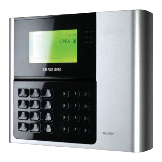
- Page 1 SSA-S2100 Standalone RFID Access Controller user manual imagine the possibilities Thank you for purchasing this Samsung product. To receive more complete service, please visit our website. www.samsungsecurity.com...
- Page 2 If this product fails to operate normally, contact the nearest service center. Never disassemble or modify this product in any way. (SAMSUNG is not liable for problems caused by unauthorized modifi cations or attempted repair.) . When cleaning, do not spray water directly onto parts of the product. Doing so may cause fi re or electric shock.
- Page 3 Apparatus shall not be exposed to dripping or splashing and no objects fi lled with liquids, such as vases, shall be placed on the apparatus. The Mains plug is used as a disconnect device and shall stay readily operable at any time. FCC Statement Caution : Any changes or modifi...
-
Page 4: Table Of Contents
contents PRODUCT INTRODUCTION Features What’s included At a glance Cable Color Scheme Cable Selection INSTALLATION AND EXTERNAL Installing the Wall Mount Bypass Diode Connection CONNECTION I/O Connection External Reader Connection INITIALIZATION Initializing the system To access the master mode Registering a master ID Name Display User Count Setup Language Setup... - Page 5 USER MANAGEMENT Registering ID in Quick mode Registering the ID To delete ID Viewing the ID list To check the number of registered IDs To remove all registered IDs To remove the master IDs Duress Mode Door Open Alarm Time Setup Arm/Disarm Two Men Operation Mode To check the number of events...
- Page 6 contents Event Memory Setup ADDITIONAL FEATURES ID Display WIEGAND Output Setup Voice Volume Setup One Time Read Version Check Input Test Output Test LCD Test Keypad Test READER Test Memory Test Communication Test Input Type Setup OTHER INFORMATION Menu Structure Default Settings TroubleShooting TROUBLESHOOTING...
-
Page 7: Product Introduction
(access and alert details, etc) on the connected computer. Keypad Registration Even if SSA-S2100/SSA-S2101 is not connected to the host PC, you can use the built-in keypad and LCD module to register or delete the card or confi gure necessary settings independently. Time Scheduling SSA-S2100/SSA-S2101 is featured by so-called time schedule, which allows you to instruct it to perform a specifi... - Page 8 External I/O Pins SSA-S2100/SSA-S2101 has 4 input pins and 4 output pins installed(2 relay and 2 TTL outputs) The input pins can receive signals from the Exit button and the Door Contact sensor, while the two relays can be connected to the Door Lock and the alarm device.
-
Page 9: What's Included
WHAT’S INCLUDED Check if the following items are included in the product package. Main Unit Wall Mount Cable (X 6) 3.5 X 40mm screws (X 4) Diode (X 2) Resistor (X 4) 3.5 X 12mm screws (X 4) (UF4004, 1N4001~4007) (2.2kΩ, 1/4W) 3 X 8mm screws (X 1) 6 X 30mm Plastic Anchor (X 4) -
Page 10: At A Glance
product introduction AT A GLANCE Front Panel This module displays the operation status of the product. The red indicator turns on when the product turns on. System Status LED The red indicator turns on when relay #1 becomes active. The yellow indicator turns on when relay #2 becomes active. 12 menu buttons ( ) are available for use. - Page 11 Rear Panel RJ45 Connector Used in TCP/IP communications. Used in TCP/IP communications. Tamper Switch Tamper switch. Fixing Hole Hole for a fi xing screw. 2-pin Connector Can be connected to the power cable. 3-pin Connector Preliminary connector for extension. 6-pin Connector Can be connected to the I/O cable.
-
Page 12: Cable Color Scheme
product introduction CABLE COLOR SCHEME ❖ 2-PIN Connector I/O Pins Signal Cable Color Power (+12V) DC +12V Earth-grounding GND (-) Black ❖ 3-PIN Connector I/O Pins Signal Cable Color RESERVED 1 Pink lwith White Stripes RESERVED 2 Sky blue with White Stripes RESERVED 3 Black ❖... -
Page 13: Cable Selection
CABLE SELECTION Description Cable Type Cable Type Product Power (DC12V) Belden #9409, 18 AWG, 2 Conductor, Unshielded (Maximum Allowable Distance : Within 3m) Belden #9409, 18 AWG, 2 Conductor, Unshielded (Maximum Allowable Distance : Within 3m) This product Reader (power and data) Belden #9512, 22 AWG, 4 Conductor, Shielded External reader This... -
Page 14: Installation And External Connection
installation and external connection INSTALLING THE WALL MOUNT Follow the instructions below to install the wall mount. Place the wall mount on the installation point and mark the 4 holes for the screws. Drill at least 4 of 6-32 holes. Drill a 1/2”... -
Page 15: Bypass Diode Connection
BYPASS DIODE CONNECTION If you connected an inductor (door locks or alarm device) to the output relay, there should occur a surge voltage while the inductor was turning on and off. If you do not connect a bypass diode to the relay, the surge voltage will cause damage to the electric circuit of the controller. - Page 16 installation and external connection I/O CONNECTION Input Connection Mon 12 / 12 / 2009 10 : 30 : 20 Door Contact Sensor: Yellow with the red stripe, GND Exit Button: Orange line, GND Connect 2.2K— to check for cut-off detection Door Contact Sensor Black - 100V-220V...
- Page 17 Output Connection Connect the 8-pin connector (relay connector) of this product as follows: COM (gray with red stripes) DOOR Mon 12 / 12 / 2009 NO (white with red stripes) 10 : 30 : 20 RELAY NC (blue with white stripes) COM (white) ALARM NO (purple)
-
Page 18: External Reader Connection
Connect the Wiegand data input line 1 of the proximity reader to the sky blue line • For a list of compliant readers (external readers), see the followings: SSA-S2100 - Standard 26bit Wiegand format proximity reader - Standard 26bit Wiegand + 8bit Burst format proximity/keypad reader... - Page 19 TCP/IP Communication Port Connection To implement TCP/IP communications for the host PC, follow the steps below: TCP/IP TCP/IP Mon 12 / 12 / 2009 Mon 12 / 12 / 2009 Mon 12 / 12 / 2009 10 : 30 : 20 10 : 30 : 20 10 : 30 : 20 Connect the RJ45 jack of the unit to the RJ45 plug, the LAN cable of the network system.
-
Page 20: Initializing The System
Initialization INITIALIZING THE SYSTEM Initializing the system using the Initialize switch Initialize the system using the Initialize switch on the rear of the product. Check the power terminal on the rear of the product and disconnect the power cable. INITIALIZE OK? While holding the Initialize switch, connect the power cable again. -
Page 21: To Access The Master Mode
TO ACCESS THE MASTER MODE Apply the power to the product. When the booting is done, press 8 consecutive times (00000000) and W E L C O M E ! ! press * * * * * * * * •... -
Page 22: Name Display
Enter the PIN for the master card to register and press EMPTY • PIN Range - SSA-S2100 : Numeric letters in 8 digits Ranges from 00000001 to 99999999 4. MASTER ID REG - SSA-S2101 : Numeric letters in 10 digits... -
Page 23: User Count Setup
USER COUNT SETUP You can select the maximum number of registered users to 10,000 or 20,000. If you set the maximum user count to 20,000, the maximum number of events will be changed to 10,000. Press the SETUP MENU button. Use the buttons to move to the MAX USER SETUP item and 5. -
Page 24: Date/Time Setup
initialization DATE/TIME SETUP Press the SETUP MENU button. Use the buttons to move to the SET DATE/TIME item and 2. SET DATE/TIME press YYYYMMDDhhmmssw _______________ Enter the values of year, month, day, hour, minute, second, and day of the week in sequence. •... -
Page 25: Baud Rate Setup
BAUD RATE SETUP This product supports 9600, 19200, 38400, and 57600 bps, and it is set to 57600 bps by default. An improper speed setting can cause a communication error so ensure that you specify the same speed in the same network. -
Page 26: Reader Mode Setup
reader mode setup READER #1 MODE READER#1 is the default reader that is built in this product. Press the SETUP MENU button. Use the buttons to move to the READER#1 MODE item and 3. READER#1 MODE press ID ONLY Use the buttons to select a reader mode. -
Page 27: Reader #1 Key Input
READER #1 KEY INPUT This enables you to use the keypad (numeric keypad) of READER #1 to enter the ID. If you want to use the registered ID (card number or PIN) to get access, set this mode to USE. Press the SETUP MENU button. -
Page 28: User Management
user management REGISTERING ID IN QUICK MODE To register ID Press the SETUP MENU button. Use the buttons to move to the REGISTRATION item and (QUICK MODE) press 1. REGISTRATION Use one of the following two ways to enter an ID: •... -
Page 29: Registering The Id
REGISTERING THE ID 1. REGISTRATION To register the ID card Press the SETUP MENU button. 1. REGISTRATION Use the buttons to move to the REGISTRATION item and 1:CARD 2:PIN press Press the button to select CARD. 1. REGISTRATION • For card registration, select the CARD to register the ID. SCANNIG…... - Page 30 PW_ TA TB model. RD MA MB LV - PIN Range SSA-S2100 : Numeric letters in 4 ~ 8 digits Ranges from 00000001 to 99999999 ID REGISTERED! SSA-S2101 : Numeric letters in 4 ~ 8 or 10 digits Ranges from 0001 to 99999999, 0000000001 to 4294967295...
-
Page 31: To Delete Id
TO DELETE ID A registered ID can be deleted by entering the ID using the card or keypad in ID DELETE mode. The number of the ID to delete will be displayed on the screen. Press the SETUP MENU button. 2.ID DELETE Use the buttons to move to the ID DELETE item and press... -
Page 32: To Check The Number Of Registered Ids
user management TO CHECK THE NUMBER OF REGISTERED IDs You can check the total number of registered IDs. Press the SETUP MENU button. Use the buttons to move to the REG. ID COUNT item and 5. REG. ID COUNT press 00123 The number of registered IDs will be shown on the screen. -
Page 33: To Remove The Master Ids
TO REMOVE THE MASTER IDs If you want to remove all master IDs (card IDs), use this menu. Press the SETUP MENU button. Use the buttons to move to the MASTER ID CLR item and 4. MASTER ID CLR press Press the button to delete all registered master IDs. -
Page 34: Door Open Alarm Time Setup
user management DOOR OPEN ALARM TIME SETUP In this menu, you can set the delay time until the product triggers the door open alarm if the door stays open after the Door Relay time. To use this function, the Door Contact sensor should have been installed on the entrance door. (see page 17) The default is ‘03’. -
Page 35: Two Men Operation Mode
TWO MEN OPERATION MODE With TWO MEN MODE active, the door will be opened if both administrator card and visitor card are entered in a row within 10 seconds. Press the SETUP MENU button. Use the buttons to move to the TWO MEN MODE item and 3.TWO MEN MODE press NOT USE... -
Page 36: To Remove All Events
user management TO REMOVE ALL EVENTS If the event memory is full or you want to change the number of IDs, you can use this menu to clear the event memory. Press the SETUP MENU button. Use the buttons to move to the EVENT CLEAR item and 2.EVENT CLEAR press 1:YES, 0:NO... -
Page 37: I/O Time Setup
I/O time setup EXIT BUTTON OUTPUT Press the SETUP MENU button. Use the buttons to move to the EXIT BUTTON item and 1.EXIT BUTTON press D R A R T 1 T 2 B Z 0 3 0 0 0 0 0 0 0 0 You can make input when the prompt blinks. -
Page 38: Auxiliary Input #1 Setup
I/O time setup AUXILIARY INPUT #1 SETUP Press the SETUP MENU button. Use the buttons to move to the AUX INPUT #1 item and 3.AUX INPUT#1 press D R A R T 1 T 2 B Z You can make input when the prompt blinks. 0 0 0 0 0 0 0 0 0 0 •... -
Page 39: Tamper Alarm Output Setup
TAMPER ALARM OUTPUT SETUP You can set the signal that you want to output if the device is dismantled forcibly. Press the SETUP MENU button. 5.TAMPER ALARM Use the buttons to move to the TAMPER ALARM item and press D R A R T 1 T 2 B Z 0 0 9 9 9 9 9 9 9 9 You can make input when the prompt blinks. -
Page 40: Duress Mode Output Setup
I/O time setup DURESS MODE OUTPUT SETUP You can specify the output time for Duress mode. Press the SETUP MENU button. Use the buttons to move to the DURESS ALARM item and 7.DURESS ALARM press D R A R T 1 T 2 B Z You can make input when the prompt blinks. -
Page 41: Door Open Timeout Setup
DOOR OPEN TIMEOUT SETUP You can set the alarm to sound if the door stays open after a specifi c wait time from when it opens. Press the SETUP MENU button. Use the buttons to move to the DOOR TIME OUT item and 9.DOOR TIME OUT press D R A R T 1 T 2 B Z... - Page 42 I/O time setup Output Setup for Level 2 IDs Accessing READER #1 Press the SETUP MENU button. Use the buttons to move to the RD1 ID OK LV2 item and 2.RD1 ID OK LV2 press • The operation time for each output is the same as in “Output Setup for D R A R T 1 T 2 B Z Level 1 IDs Accessing READER #1”...
-
Page 43: Reader #1 Error Output Setup
READER #1 ERROR OUTPUT SETUP READER #1 ID Error Output Setup Press the SETUP MENU button. Use the buttons to move to the RD1 ID ERROR item and press 5.RD1 ID ERROR You can make input when the prompt blinks. D R A R T 1 T 2 B Z 0 0 0 3 0 0 0 0 0 0 •... -
Page 44: Output Setup For Level Ids Accessing Reader #2
I/O time setup OUTPUT SETUP FOR LEVEL IDS ACCESSING READER #2 Output Setup for the event of Level 1 IDs accessing the READER #2 Press the SETUP MENU button. Use the buttons to move to the RD2 ID OK LV1 item and 8.RD2 ID OK LV1 press D R A R T 1 T 2 B Z... -
Page 45: Reader #2 Error Output Setup
Output Setup for Level 4 IDs Accessing READER #2 Press the SETUP MENU button. Use the buttons to move to the RD2 ID OK LV4 item and 11.RD2 ID OK LV4 press • The operation time for each output is the same as in “Output Setup for D R A R T 1 T 2 B Z Level 1 IDs Accessing READER #2”... - Page 46 I/O time setup READER #2 Time Schedule Error Output Setup Press the SETUP MENU button. Use the buttons to move to the RD2 T/S ERROR item and 13.RD2 T/S ERROR press • D R A R T 1 T 2 B Z The operation time for each output is the same as in “READER #2 ID Error 0 0 0 3 0 0 0 0 0 0 Output Setup”...
-
Page 47: Advanced Setup
advanced setup TIME UNIT SETUP You can use this menu to specify the time unit. Press the SETUP MENU button. Use the buttons to move to the TIME UNIT item and press 3.TIME UNIT UNIT: 1SEC Use the buttons to specify the time unit and press •... -
Page 48: Antipassback Mode
advanced setup ANTIPASSBACK MODE Antipassback mode is used to prevent an identical user from entering or exiting the door twice or more consecutively. This mode is available only with an Exit reader dedicated to detecting exits, which is not available in a system that is solely using the Exit button to exit the door. -
Page 49: Holiday Setup
Use the numeric buttons to enter start or end time in 8 digits. 1.TIME SCHEDULE • If an entry is invalid, the “INVALID NUMBER” message will appear. T/S CODE: 01 HOL INTERVAL: 00:00 – 00:00 Repeat steps 3 through 4 above to set other time schedules. Upon completion of all time schedules, press to exit from the menu. -
Page 50: Holiday Code Setup
advanced setup HOLIDAY CODE SETUP The Holiday Code setting allows you to link a Holiday Schedule to a Time Schedule.. A Time Schedule has 5 Time Intervals for holidays and the Time Intervals are applied only to the dates of this Holiday Schedule. The Holiday Code ‘00’... -
Page 51: Reader Mode Time Schedule
READER MODE TIME SCHEDULE READER #1 MODE TIME SCHEDULE There are 2 reader modes (in READER #1) including ID Mode and ID+PW Mode. Unless otherwise set specifi cally, all registered users should be verifi ed according to the reader mode in use. However you may allow entry with card only during a certain time interval for all users. -
Page 52: Voice Message Time Schedule
advanced setup VOICE MESSAGE TIME SCHEDULE The Voice Message Time Schedule function allows you to apply time schedules to the voice message output and mute them at other times. To apply a time schedule code, enter the time schedule code you want. Within the time range assigned by the time schedule, voice messages will be played while at other times, they will not be played. -
Page 53: Input Time Schedule Setup
INPUT TIME SCHEDULE SETUP You can assign a Time Schedule Code to each input to activate the input only during that period. The default Time Schedule Code for every input is “00”, which means no Time Schedule is applied to them. Changing these settings can be very useful when you want to activate PIR sensor during a certain period of time. -
Page 54: Event Memory Setup
additional features EVENT MEMORY SETUP Press the SETUP MENU button. Use the buttons to move to EVENT MEMORY and press 1.EVENT MEMORY NOT USE Use the buttons to select either USE or NOT USE and press • USE : When the event memory is full, it gives out an error message and 1.EVENT MEMORY maintains all events stored in the memory. -
Page 55: Wiegand Output Setup
WIEGAND OUTPUT SETUP Press the SETUP MENU button. Use the buttons to move to the WIEGAND OUTPUT item 7. WIEGAND OUTPUT and press NOT USE Use the buttons to select either USE or NOT USE and press • USE : It sends 26 bit Wiegand Output (34 bit for SSA-S2101 series) 7. -
Page 56: One Time Read
additional features ONE TIME READ If the menu is set to “USE”, the card authentication will not take place for the next 30 seconds after an instance of authenticating a registered card. Press the SETUP MENU button. Use the buttons to move to ONE TIME READ and press 4.ONE TIME READ NOT USE... -
Page 57: Input Test
INPUT TEST This feature allows you to test settings for each input. Press the SETUP MENU button. Use the buttons to move to the INPUT TEST item and press 2.INPUT TEST EX DC I1 I2 TP The corresponding value changes upon input. •... -
Page 58: Lcd Test
LCD TEST This feature allows you to test the LCD status. The SAMSUNG logo will appear rolling up and down. At this time you can check any abnormality in the LCD. Press the SETUP MENU button. Use the buttons to move to the LCD TEST item and press 4.LCD TEST... -
Page 59: Reader Test
Press any key to move to the parent menu. If the Data Memory has a problem, the “TEST FAILED” message will be displayed on the screen. If this is the case, contact the nearest Samsung Service Center for technical support. English59... -
Page 60: Communication Test
PRESS ANY KEY… Press any key to move to the parent menu. If the communication is malfunctioning, the “TEST FAILED!!!” message will be displayed. If this is the case, contact the nearest Samsung Service Center for technical support. 60_ Additional Features... -
Page 61: Input Type Setup
INPUT TYPE SETUP Either one of NO(00) or NC(01) is available for the input type. The default setting is ‘00(Normal Open)’. Press the SETUP MENU button. Use the buttons to move to the INPUT TYPE item and press 13.INPUT TYPE 0 0 : N O , 0 1 : N C E X D C I 1 I 2 T P You can make input when the prompt blinks. -
Page 62: Menu Structure
other information MENU STRUCTURE Menu Structure of the [F1] button You can set Language, Date/Time and READER modes. ENGLISH F1 button LANGUAGE ESPANOL PORTUGUES 한국어 SET DATE/ TIME ID ONLY READER #1 MODE ID+P/W ID ONLY READER #2 MODE ID+PW NOT USE RD#1 KEY INPUT NOT USE... - Page 63 Menu Structure of the [F3] button You can set Voice Volume, Arm/Disarm, Two Men Operation, One Time Read, Number of Users, and Name Display. F3 button VOICE VOLUME 0 (MUTE) ~ 4 (MAXIMUM) ARM/DISARM NOT USE TWO MEN MODE NOT USE ONE TIME READ 10,000 MAX USER SETUP...
- Page 64 other information Menu Structure of the [F5] button You can set Exit Key Output, Door Contact Sensor, Aux Input #1 and #2, Tamper Alarm Output, Cut Off Output, Duress Alarm Output, Arm/Disarm Output, Door Open timeout Output, Input/Output Time Schedule, Input Cut Off Check, and Input Type.
- Page 65 Menu Structure of the [F6] button You can set Output for Accessible levels for READER #1 and #2 ID, READER #1 and #2 ID Error Output, READER #1 and #2 Time Schedule Error Output, READER #1 and #2 Antipassback Error Output. F6 button RD1 ID OK LV1 RD1 ID OK LV2...
- Page 66 other information Menu Structure of the [F7] button You can register or delete IDs and register the master ID. You can also view the ID list, ID count and event count. CARD F7 button REGISTRATION ID DELETE ID LIST MASTER ID REG REG.
- Page 67 Menu Structure of the [F9] button You can check the system version. You can also test the input, output, LCD, keypad, reader, memory and communication status. F9 button FIRMWARE VER INPUT TEST OUTPUT TEST LCD TEST KEYPAD TEST READER TEST MEMORY TEST COMM TEST Menu Structure of the [F12] button...
-
Page 68: Default Settings
other information DEFAULT SETTINGS Output Settings for Input Sources Output Door Relay Alarm Relay TTL#1 TTL#2 Buzzer Input (DR) (AR) (T1) (T2) (BZ) [1] Exit Button [2] Door Contact [3] AUX Input #1 [4] AUX Input #2 [5] TAMPER Alarm [6] Cut Off Alarm [7] DURESS ALARM [8] ARM/DISARM OUT... - Page 69 Output Setting for Authentication Output Door Relay Alarm Relay TTL#1 TTL#2 Buzzer Input (DR) (AR) (T1) (T2) (BZ) [1] Reader#1 ID OK LV1 [2] Reader#1 ID OK LV2 [3] Reader#1 ID OK LV3 [4] Reader#1 ID OK LV4 [5] Reader#1 ID Error [6] Reader#1 T/S Error [7] Reader#1 APB Error [8] Reader#2 ID OK LV1...
-
Page 70: Troubleshooting
After all the initialization process is completed, the system will be operating on the normal mode and the screen will display the SAMSUNG logo, Date and Time information. If the trouble persists after following the procedures above, contact a designated service center. - Page 71 PROBLEM SOLUTION The “ACCESS DOOR ERR” message 1) If the unit used to operate properly before, it is likely that there has been an electric appears when a RF ID card is being read. shock that damaged the internal memory and data. Please initialize the unit as instructed in the manual.
-
Page 72: Product Specifi Cations
PRODUCT SPECIFICATIONS Item SSA-S2100 SSA-S2101 User 10,000 / 20,000 Users (Selectable) Event Buffer 20,000 / 10,000 Event Buffers (Selectable) Power / Current DC 12V / Max. 420mA 1ea: 26bit Wiegand, 1ea: 34bit Wiegand, Reader Port 8bit Burst for PIN for Anti-Pass-Back... - Page 73 Correct Disposal of This Product (Waste Electrical & Electronic Equipment) (Applicable in the European Union and other European countries with separate collection systems) This marking on the product, accessories or literature indicates that the product and its electronic accessories (e.g. charger, headset, USB cable) should not be disposed of with other household waste at the end of their working life.
Need help?
Do you have a question about the SSA-S2100 and is the answer not in the manual?
Questions and answers