
Related Manuals for Samsung SSA-R1001


Summary of Contents for Samsung SSA-R1001
- Page 1 SSA-R1001 SSA-R1101 Quick Guide Contents Product Introduction Installation and External Connection...
-
Page 2: Product Introduction
Product Introduction WHAT’S INCLUDED Check if the following items are included in the product package. What’s in cluded in SSA-R1001 3.5x40mm screws (x2) SSA-R1001 READER Module 3.5x25mm screws (x2) Quick Guide CD Manual Ferrite Core Bezel 6x30mm Plastic Anchor (x2) - Page 3 QUICK GUIDE QUICK GUIDE What’s included in SSA-R1101 3.5x40mm screws (x2) SSA-R1101 READER Module 3.5x25mm screws (x2) Quick Guide CD Manual Ferrite Core Bezel 6x30mm Plastic Anchor (x2) English_ English_...
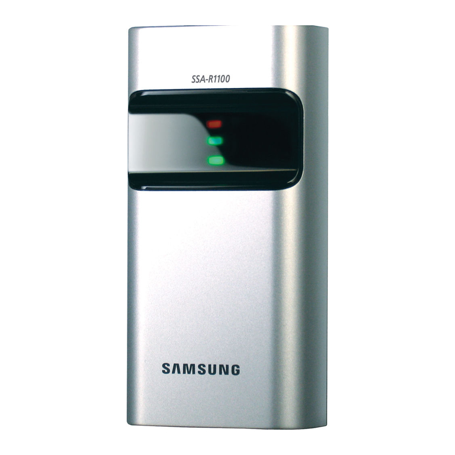
- Page 4 AT A GLANCE Front/Rear _Installation and External Connection _Product Introduction...
- Page 5 QUICK GUIDE QUICK GUIDE Displays the system operation status using red and green indicators. Buzzer Piezo buzzer. Connection Cable Used to connect to the power or I/O cable. Fixing Hole Fixing hole for wall-mounting. English_ English_...
-
Page 6: Cable Color Scheme
CABLE COLOR SCHEME Item Cable Color Signal Line Description DC +12V DC +12V supplied Power Black Earth-grounding for power Blue Buzzer Control BUZZER Control Input Port Input Yellow LED Control LED Control Input Port Green Out Wiegand 0 Wiegand Data 0 Output Port Output White Out Wiegand 1... -
Page 7: Installation
QUICK GUIDE Installation and External Connection - Inserted in the doorframe / attached to the wall INSTALLATION Two 6-32 or M3 holes are 3.3” (8.38 cm) away from Upper each other vertically; between the two exists one 1/2” 6-32 hole hole through which the reader cables are arranged. -
Page 8: Precautions On Installation
PRECAUTIONS ON INSTALLATION If installing on a metal wall If you install the reader on a metal wall, the read range may be reduced. To avoid this problem, it is recommended to insert the Metal spacer between the metal wall and the reader as shown Wall below. - Page 9 QUICK GUIDE If installing more than one reader side by side or front and back If you install more than one reader side by side or front and back, the read range may be reduced. In Minimum 20cm this case, if you present a card to one reader, the other reader may recognize the same card, meaning both readers read the same card simultaneously.
-
Page 10: External Connection
EXTERNAL CONNECTION Wiring Diagram SSA-R1001/SSA-R1101 Buzzer Control In Blue RS-232(TX) Purple LED Control In Yellow CONTROLLER Wiegand Data 0 Out Green Black RS-232(GND) Wiegand Data 1 Out White Black DC +12V POWER _Installation and External Connection... - Page 11 QUICK GUIDE Item Cable Color Connect the DC+12V to the red line. Power Supply Unit Connect GND to the black line. Connect the green line of the product to the Wiegand D0 input port of the controller. Wiegand Connection Connect the white line of the product to the Wiegand D1 input port of the controller. To control the LED indicators, connect the yellow line to the output port (relay) of the LED Control controller.
- Page 12 TEL: +82-70-7147-8740~60, FAX: +82-31-8018-3745 SAMSUNG TECHWIN EUROPE LTD. SAMSUNG TECHWIN AMERICA Inc. Samsung House, 1000 Hillswood Drive, Hillswood Business Park Chertsey, 1480 Charles Willard St, Carson, CA 90746, UNITED STATES Surrey, UNITED KINGDOM KT16 OPS Tol Free: +1-877-213-1222, FAX: +1-310-632-2195 TEL: +44-1932-45-5300, FAX: +44-1932-45-5325 www.samsungcctvusa.com...
- Page 13 SSA-R1001 SSA-R1101 Guide de prise en main rapide Table des matières Lancement du produit Installation et connexion externe...
- Page 14 Lancement du produit CONTENU Vérifi ez si les éléments suivants sont inclus dans l’emballage. Éléments inclus dans l’emballage du SSA-R1001 É Vis 3,5 x 40 mm (x2)) Châssis du Vis 3,5 x 25 mm (x2) Guide de prise en Module LECTEUR Manuel sur CD Tore magnétique...
- Page 15 GUIDE DE PRISE EN MAIN RAPIDE GUIDE DE PRISE EN MAIN RAPIDE Éléments inclus dans l’emballage du SSA-R1101 Vis 3,5 x 40 mm (x2) Châssis du Vis 3,5 x 25 mm (x2) Guide de prise en Module LECTEUR Manuel sur CD Tore magnétique SSA-R1101 Bride d’ancrage en plastique...
- Page 16 D’UN COUP D’OEIL Avant/Arrière _installation et connexion externe _Lancement du produit...
- Page 17 GUIDE DE PRISE EN MAIN RAPIDE GUIDE DE PRISE EN MAIN RAPIDE Voyants DEL Affi che l’état de fonctionnement du système à l’aide de voyants rouge et vert. Sonnerie Sonnerie piézoélectrique. Câble de connexion Utilisé pour le branchement de l’alimentation ou du câble E/S. Trou de fi...
- Page 18 SCHÉMA DES COULEURS DE CÂBLE Élément Couleur de câble Ligne de signaux Description Rouge CC +12 V CC + 12 V fournis Alimentation Noir Mise à la terre de l’alimentation Bleu Commande sonnerie Port d’entrée de la commande SONNERIE Entrée Jaune Commande DEL Port d’entrée de la commande DEL...
- Page 19 GUIDE DE PRISE EN MAIN RAPIDE Installation et connexion externe - Montage sur cadre de porte / fi xation au mur INSTALLATION Deux trous 6-32 ou M3 sont percés à une distance Haut verticale de 8,38 cm (3,3”), entre lesquels est pratiqué Trou 6-32 un trou de 1/2”...
-
Page 20: Précautions D'installation
PRÉCAUTIONS D’INSTALLATION En cas d’installation sur un mur métallique Si vous installez le lecteur sur un mur métallique, la plage de lectures pourra s’en trouver réduite. Pour éviter ce problème, il est recommandé d’insérer une cale d’espacement entre le mur métallique et le lecteur, tel métallique qu’illustré... - Page 21 GUIDE DE PRISE EN MAIN RAPIDE En cas d’installation de deux lecteurs côte à côte ou à l’avant et à l’arrière Si vous installez deux lecteurs côte à côte ou à l’avant et à l’arrière, la plage de lectures pourra s’en 20 cm trouver réduite.
-
Page 22: Connexion Externe
CONNEXION EXTERNE Schéma de câblage SSA-R1001/SSA-R1101 Entrée de commande sonnerie Bleu RS-232(TX) Mauve Entrée de commande DEL Jaune CONTRÔLEUR ORDINATEUR Sortie de données Wiegand 0 Vert Noir RS-232(GND) Sortie de données Wiegand 1 Blanc Rouge Noir CC +12 V ALIMENTATION... - Page 23 GUIDE DE PRISE EN MAIN RAPIDE Élément Couleur de câble Connectez le courant CC+12 V à la ligne rouge. Module d’alimentation Connectez GND à la ligne noire. Connectez la ligne verte du produit au port d’entrée Wiegand D0 du contrôleur. Connexion Wiegand Connectez la ligne blanche du produit au port d’entrée Wiegand D1 du contrôleur.
- Page 24 TEL: +82-70-7147-8740~60, FAX: +82-31-8018-3745 SAMSUNG TECHWIN EUROPE LTD. SAMSUNG TECHWIN AMERICA Inc. Samsung House, 1000 Hillswood Drive, Hillswood Business Park Chertsey, 1480 Charles Willard St, Carson, CA 90746, UNITED STATES Surrey, UNITED KINGDOM KT16 OPS Tol Free: +1-877-213-1222, FAX: +1-310-632-2195 TEL: +44-1932-45-5300, FAX: +44-1932-45-5325 www.samsungcctvusa.com...
- Page 25 SSA-R1001 SSA-R1101 Kurzanleitung Inhalt Produkteinführung Montage und externe Verkabelung...
- Page 26 Produkteinführung LIEFERUMFANG Überprüfen Sie, ob die folgenden Teile in der Produktverpackung enthalten sind. Was ist im Lieferumfang des SSA-R1001 enthalten 3,5 mm x 40 mm Schrauben (2 Stk.) Blende für ABLESE-Modul 3,5 mm x 25 mm Schrauben (2 Stk.) Kurzanleitung...
- Page 27 KURZANLEITUNG KURZANLEITUNG Was ist im Lieferumfang des SSA-R1101 enthalten 3,5 mm x 40 mm Schrauben (2 Stk.) Blende für ABLESE-Modul 3,5 mm x 25 mm Schrauben (2 Stk.) Kurzanleitung Handbuch auf CD Ferritkern SSA-R1101 6 x 30 mm Plastikdübel (2 Stk.) Deutsch_ Deutsch_...
-
Page 28: Auf Einen Blick
AUF EINEN BLICK Vordere/hintere _Montage und externe Verkabelung _Produkteinführung... - Page 29 KURZANLEITUNG KURZANLEITUNG Zeigt den Status des Systembetriebs mithilfe von roten und grünen Anzeigen. Signalgeber Piezo Signalgeber. Verbindungskabel Zum Verbinden des Ein-/Ausschalters oder I/O-Kabels. Befestigungsbohrung Befestigungsbohrung für Wandmontage. Deutsch_ Deutsch_...
- Page 30 FARBSCHEMA FÜR VERKABELUNG Position Kabelfarbe Signalleitung Beschreibung +12V DC Versorgung mit +12 V Gleichstrom Stromzufuhr Schwarz ERDUNG Erdungsanschluss Eingangsanschluss für SIGNALTON- Blau Signalton-Steuerung Steuerung Eingang Gelb LED-Anzeige Eingangsanschluss für LED-Anzeige Grün Ausgang Wiegand 0 Wiegand Data 0 Ausgangsanschluss Ausgang Weiß Ausgang Wiegand 1 Wiegand Data 1 Ausgangsanschluss RS-232 Ausgangsanschluss für...
-
Page 31: Montage
KURZANLEITUNG Montage und externe Verkabelung - Befestigung am Türstock/an der Wand MONTAGE Zwei Löcher für 6-32 oder M3 Schrauben befi nden sich Oben senkrecht untereinander in einem Abstand von 3,3” Loch für 6-32 Schraube (8,38 cm); zwischen den beiden befi ndet sich ein Loch 1,7”... - Page 32 MONTAGEHINWEISE Bei der Montage an einer Metallwand Wenn Sie das Lesegerät an einer Metallwand montieren, kann sich die Lesereichweite verringern. Zur Vermeidung dieses Problems wird empfohlen, zwischen Metallwand der Metallwand und dem Lesegerät wie unten dargestellt einen Abstandhalter einzufügen. Abstandhalter Lesegerät _Montage und externe Verkabelung...
- Page 33 KURZANLEITUNG Bei der Montage von mehr als einem Lesegerät nebeneinander oder vor- bzw. hintereinander Wenn Sie mehr als ein Lesegerät nebeneinander oder vor- bzw. hintereinander montieren, kann sich die Lesereichweite verringern. Wenn Sie in diesem Mindestens 20 cm Fall eine Karte zum Lesegerät führen, erkennt das andere Lesegerät die gleiche Karte, d.
- Page 34 EXTERNE VERKABELUNG Verdrahtungsplan SSA-R1001/SSA-R1101 Eingang Signalton-Steuerung Blau RS-232(TX) Lila Eingang LED-Anzeige Gelb STEUERUNG Ausgang Wiegand Data 0 Grün Schwarz RS-232(Erdung) Ausgang Wiegand Data 1 Weiß Schwarz +12V DC ERDUNG STROMQUELLE _Montage und externe Verkabelung...
- Page 35 KURZANLEITUNG Position Kabelfarbe Verbinden Sie das rote Kabel mit dem +12 V Gleichstromanschluss. Netzgerät Verbinden Sie das schwarze Kabel mit dem Erdungsanschluss. Verbinden Sie das grüne Kabel des Produkts mit dem Wiegand D0 Eingangsanschluss der Steuerung. Wiegand- Verbindung Verbinden Sie das weiße Kabel des Produkts mit dem Wiegand D1 Eingangsanschluss der Steuerung.
- Page 36 TEL: +82-70-7147-8740~60, FAX: +82-31-8018-3745 SAMSUNG TECHWIN EUROPE LTD. SAMSUNG TECHWIN AMERICA Inc. Samsung House, 1000 Hillswood Drive, Hillswood Business Park Chertsey, 1480 Charles Willard St, Carson, CA 90746, UNITED STATES Surrey, UNITED KINGDOM KT16 OPS Tol Free: +1-877-213-1222, FAX: +1-310-632-2195 TEL: +44-1932-45-5300, FAX: +44-1932-45-5325 www.samsungcctvusa.com...
- Page 37 SSA-R1001 SSA-R1101 Manual de consulta rápida Índice Información del producto Instalación y conexión externa...
-
Page 38: Información Del Producto
Información del producto COMPONENTES Compruebe si se incluyen los siguientes elementos en el paquete del producto. Componentes de SSA-R1001 2 tornillos de 3,5x40 mm Carcasa de Módulo de Manual de 2 tornillos de 3,5x25 mm CD de manual Núcleo de ferrita... - Page 39 MANUAL DE CONSULTA RÁPIDA MANUAL DE CONSULTA RÁPIDA Componentes de SSA-R1101 2 tornillos de 3,5x40 mm Carcasa de Módulo de Manual de 2 tornillos de 3,5x25 mm CD de manual Núcleo de ferrita SSA-R1101 LECTOR consulta rápida 2 tacos de plástico de 6x30 mm Español_ Español_...
- Page 40 VISTA Frontal/trasera _Instalación y conexión externa _Información del producto...
- Page 41 MANUAL DE CONSULTA RÁPIDA MANUAL DE CONSULTA RÁPIDA Muestra el estado d funcionamiento del sistema utilizando indicadores rojo y verde. Zumbador Zumbador piezoeléctrico. Cable de conexión Se utiliza para la alimentación o el cable de E/S. Orifi cio de fi jación Orifi...
- Page 42 ESQUEMA DE COLORES DE CABLES Elemento Color de cable Línea de señal Descripción Rojo CC 12V Se suministra +12V de CC Alimentación Negro Toma de tierra para alimentación Puerto de entrada de control de Azul Control de zumbador ZUMBADOR Entrada Amarillo Control de LED Puerto de entrada de control de LED...
-
Page 43: Instalación
MANUAL DE CONSULTA RÁPIDA Instalación y conexión externa - Insertado en el marco de la puerta / sujeto a la pared INSTALACIÓN Dos orifi cios 6-32 o M3 se ubican a 8,38 cm (3,3 pulg.) Parte superior verticalmente entre sí; entre los dos existe un orifi cio de Orifi... -
Page 44: Precauciones Sobre La Instalación
PRECAUCIONES SOBRE LA INSTALACIÓN Si se instala en una pared metálica Si instala el lector en una pared metálica, es posible que se reduzca el alcance de lectura. Para evitar este problema, se recomienda insertar el Pared espaciador entre la pared metálica y el lector como se metálica muestra a continuación. - Page 45 MANUAL DE CONSULTA RÁPIDA Si se instala más de un lector uno al lado del otro o confrontados Si instala más de un lector uno al lado del otro o confrontados, es posible que se reduzca el alcance Mínimo 20 cm de lectura.
-
Page 46: Conexiones Externas
CONEXIONES EXTERNAS Diagrama de cableado SSA-R1001/SSA-R1101 Entrada de control de zumbador Azul RS-232(TX) Violeta Entrada de control de LED Amarillo CONTROLADOR Salida 0 de datos Wiegand Verde Negro RS-232(GND) Salida 1 de datos Wiegand Blanco Rojo Negro DC +12V ALIM. - Page 47 MANUAL DE CONSULTA RÁPIDA Elemento Color de cable Unidad de Conecte DC+12V a la línea roja. alimentación Conecte GND a la línea negra. eléctrica Conecte la línea verde del producto a la puerta entrada de Wiegand D0 del controlador. Conexión Wiegand Conecte la línea blanca del producto a la puerta entrada de Wiegand D1 del controlador.
- Page 48 TEL: +82-70-7147-8740~60, FAX: +82-31-8018-3745 SAMSUNG TECHWIN EUROPE LTD. SAMSUNG TECHWIN AMERICA Inc. Samsung House, 1000 Hillswood Drive, Hillswood Business Park Chertsey, 1480 Charles Willard St, Carson, CA 90746, UNITED STATES Surrey, UNITED KINGDOM KT16 OPS Tol Free: +1-877-213-1222, FAX: +1-310-632-2195 TEL: +44-1932-45-5300, FAX: +44-1932-45-5325 www.samsungcctvusa.com...
-
Page 49: Guida Rapida
SSA-R1001 SSA-R1101 Guida rapida Sommario Presentazione del prodotto Installazione e collegamento esterno... -
Page 50: Presentazione Del Prodotto
Presentazione del prodotto CONTENUTO DELLA CONFEZIONE Controllare che i seguenti componenti siano compresi nel pacchetto del prodotto. Contenuto della confezione di SSA-R1001 Viti da 3,5x40 mm (x2) Mascherina di Modulo LETTORE Viti da 3,5x25 mm (x2) Guida rapida Manuale su CD... - Page 51 GUIDA RAPIDA GUIDA RAPIDA Contenuto della confezione di SSA-R1101 Viti da 3,5x40 mm (x2) Mascherina di Modulo LETTORE Viti da 3,5x25 mm (x2) Guida rapida Manuale su CD Nucleo in ferrite SSA-R1101 Tassello di plastica da 6x30 mm (x2) Italiano_ Italiano_...
-
Page 52: Panoramica Generale
PANORAMICA GENERALE Vista anteriore/posteriore _Installazione e collegamento esterno _Presentazione del prodotto... - Page 53 GUIDA RAPIDA GUIDA RAPIDA Visualizza lo stato di funzionamento del sistema utilizzando indicatori di colore rosso e verde. Avvisatore acustico Avvisatore acustico piezoelettrico Cavo di collegamento Utilizzato per effettuare il collegamento all’alimentazione o per collegare il cavo I/O. Foro di fi ssaggio Foro di fi...
- Page 54 SCHEMA DEI COLORI DEI CAVI Elemento Colore cavo Linea di segnale Descrizione Rosso CC +12V Alimentazione CC 12V Alimentazione Nero Collegamento a massa per alimentazione Controllo avvisatore Porta di ingresso controllo avvisatore acustico acustico Ingresso Giallo Controllo LED Porta di ingresso controllo LED Verde Out Wiegand 0 Porta di uscita 0 dati Wiegand...
-
Page 55: Installazione
GUIDA RAPIDA Installazione e collegamento esterno - Inserimento nel telaio della porta / attacco a parete INSTALLAZIONE Ci sono due fori per viti 6-32 o M3 distanti 3,3” (8,38 Parte superiore cm) cm l’uno dall’altro in verticale; tra i due è presente Foro per vite 6-32 un foro da 1/2”... -
Page 56: Precauzioni Per L'installazione
PRECAUZIONI PER L’INSTALLAZIONE Installazione su una parete metallica Se il lettore viene installato su una parete metallica, il campo di lettura potrebbe diminuire. Per evitare questo problema, si raccomanda di inserire il Parete distanziale tra la parete metallica e il lettore come indicato metallica sotto. - Page 57 GUIDA RAPIDA Installazione di più lettori fi anco a fi anco oppure fronte/retro Se si installano più lettori fi anco a fi anco oppure fronte/retro, il campo di lettura potrebbe diminuire. Minimo 20 cm In questo caso, se si fa passare una scheda su un lettore, questa potrebbe essere riconosciuta anche dall’altro lettore: la stessa scheda verrebbe quindi #Lettore 1...
-
Page 58: Schema Elettrico
COLLEGAMENTO ESTERNO Schema elettrico SSA-R1001/SSA-R1101 Ingresso controllo avvisatore acustico RS-232(TX) Viola Ingresso controllo LED Giallo CONTROLLER Uscita 0 dati Wiegand Verde Nero RS-232 (massa) Uscita 1 dati Wiegand Bianco Rosso Nero CC +12V ALIMENTAZIONE _Installazione e collegamento esterno... - Page 59 GUIDA RAPIDA Elemento Colore cavo Collegare l’alimentazione CC 12V al cavo rosso. Unità di alimentazione Collegare la massa al cavo nero. Collegare il cavo verde del prodotto alla porta di ingresso Wiegand D0 del controller. Connessione Wiegand Collegare il cavo bianco del prodotto alla porta di ingresso Wiegand D1 del controller. Per controllare gli indicatori LED, collegare il cavo giallo alla porta di uscita (relè) del Controllo LED controller.
- Page 60 TEL: +82-70-7147-8740~60, FAX: +82-31-8018-3745 SAMSUNG TECHWIN EUROPE LTD. SAMSUNG TECHWIN AMERICA Inc. Samsung House, 1000 Hillswood Drive, Hillswood Business Park Chertsey, 1480 Charles Willard St, Carson, CA 90746, UNITED STATES Surrey, UNITED KINGDOM KT16 OPS Tol Free: +1-877-213-1222, FAX: +1-310-632-2195 TEL: +44-1932-45-5300, FAX: +44-1932-45-5325 www.samsungcctvusa.com...
Need help?
Do you have a question about the SSA-R1001 and is the answer not in the manual?
Questions and answers