
Related Manuals for Avipas SWIT-AV-1362


Summary of Contents for Avipas SWIT-AV-1362
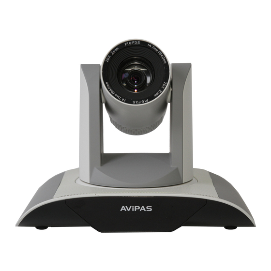
- Page 1 Model: AV-1362 H.264 HD Video Conferencing Camera User Manual V1.1 Please Read this User Manual throughout before using.
- Page 2 Attentions Electric Safety Installation and operation must accord with electric safety standard Caution to transport Avoid stress,vibration and soakage in transport,storage and installation. Polarity of power supply The power supply of the product is ±12V,the max electrical current is 2A .Polarity of the power supply drawing.
- Page 3 To make sure no obstacle in rotation range. Never power on before installation is completed. Don’t disassemble discretionarily. We are not responsible for any unauthorized modification or dismantling. Attention Electromagnetic filed under certain rate may affect camera image!
- Page 4 This Limited Warranty covers any defects in material under normal use during the Warranty Period. During the Warranty Period, AVIPAS Inc. will repair or replace, at no charge and products that proves defective because of improper material, under normal use and maintenance.
-
Page 6: Table Of Contents
Content 1. Fast Installation ................................. 6 1.1 Camera Interface Explanation ........................6 1.2 Power on Initial Configuration ........................7 1.3 Video output ..............................7 1.4 BRACKET MOUNTING ..........................8 2. Product overview ..............................11 2.1 Product introduction ............................. 11 2.2 Main Features ............................... 13 2.3 Technical specification.......................... -
Page 7: Fast Installation
6.2 Troubleshooting ............................63 1. Fast Installation 1.1 Camera Interface Explanation... -
Page 8: Power On Initial Configuration
Figure 1.1. AV-1362 series Camera lens RS232 control interface (input ) Camera base 10/100M Network interface Remote Controller Receiver light DVI-I interface(including HDMI signal) Bottom DIP switch 10. USB3.0 interface Tripod screw hole 11. DC12V Input Power Supply Socket Installation Orientation Hole 12. -
Page 9: Bracket Mounting
1) video output from LAN Network cable connection port: AV-1362--No. 8 in Figure1.1. Webpage Login: open your browser and enter 192.168.5.163 in the address bar (factory default); press Enter to enter into the login page; click on the “player is not installed,please download and install!"... - Page 11 2) Upside-down installation steps...
-
Page 12: Product Overview
2. Product overview 2.1 Product introduction 2.1.1 Product model Model No.: AV-1362 Model NO.X—XXX—XXX—XX IR ---IR remote controller WR---wireless remote controller AV-1362---USB3.0 interface 20x optical zoom lens S---1080P60 downward compatibility M---1080P30downward compatibility Please refer to corresponding features in this manual. - Page 13 2.1.2 Dimension Figure 2.2 Camera dimension 2.1.3 Accessory When you unpack,check that all the supplied accessories are included:...
-
Page 14: Main Features
Model NO. AV-1362 Power adapter 1piece RS232 cable 1piece Standard User manual 1piece Double-side glue shim 4pcs IR Remote controller or Accessory wireless controller 1piece Optional USB3.0 cable Wall mounting bracket(optional) Upside-down mounting bracket(optional) 2.2 Main Features 2.2.1 Camera performance This series camera offers perfect functions,superior performance and rich interfaces. - Page 15 moves smoothly and very quickly to designated position. 5)Multi-Format Video Outputs: support DVI (HDMI), USB,wired LAN and wireless LAN interfaces. 6) 6)Multiple remote controls: There is IR remoter and 2.4G wireless remote for options. The 2.4G wireless remote controller will not be affected by angle,distance or IR interference. Support transparent transmission function.
-
Page 16: Technical Specification
2.3 Technical specification Model AV-1362 Camera Parameter Optical Zoom 20X,f=4.7~94mm Sensor 1/2.8 inch high quality HD CMOS sensor 16: 9 2.07 megapixel AV-1362 model: 1920X1080P60/50/30/25;1280X720P60/50/30/25;960X540P30;640X360P30;6 Effective Pixels 40X480P30;352X288P30;960X540P30 Video Format AV-1362 model :U3 compatible with U2: 960X540P30; 640X360P30; 1280X720P10/15; 720X576P50; 720X480P60; 640X480P30;... - Page 17 Image Code Stream Dual stream output Video Compression H.264,H.265 Format Control Signal Interfac RS-232 Ring through RS232 output Control Protocol VISCA/Pelco-D/Pelco-P; Baud Rate: 115200/9600/4800/2400bps Audio Input Interface Double track 3.5mm linear input; Audio Compression AAC/MP3/PCM Audio compression Format HD IP Interface 100M IP port(100BASE-TX);...
-
Page 18: Interface Instruction
Working Temperature -10℃~+50℃ Dimension 258mmX172mmX168mm Weight 1.54KG Remote Operation (IP) Remote Upgrade,Reboot and Reset Accessory power supply,RS232 control cable,remoter,manual,warranty card 2.4 Interface instruction 2.4.1 External Interface External interface of AV-1362 model: RS232 input,LAN,DVI(HDMI)output,USB3.0 output,DC12V power interface. Figure 2.3 AV-1362 model external interface diagram 2.4.2 Bottom DIP Switch AV-1362 model Bottom DIP Switch diagram shown in Figure 2.4,... - Page 19 Figure 2.4 Bottom DIP Switch diagram AV-1362 model two DIP switches are set to ON or OFF to select different modes of operation as shown in Table 2.3 Table 2.3 DIP Switch setting Explanation Working mode USB3.0 software upgrade mode ARM software upgrade mode Note: Working mode can be applicable for web upgrade.
- Page 20 Table 2.4 Rotary Dial corresponding to the video formats Dial-up video format Dial-up video format 1080P60 720P30 1080P50 720P25 1080I60 1080P59.94 1080I50 1080I59.94 720P60 720P59.94 720P50 1080P29.97 1080P30 720P29.97 Display the video Figure 2.5 Rotary Dial diagram 1080P25 format set on the menu Note: 1.After switching DIP,you need to restart the camera to take effect.
- Page 21 No Connection 1) RS232 (DB9) Port Definition Port Definition Data Carrier Detect Receive Data Transmit Data Data Terminal Ready System Ground Data Set Ready Request to Send Clear to Send Ring Indicator 2) VISCA networking as shown below:...
-
Page 22: Application Instruction
Camera cascade connection method Camera 1 Camera 2 1.DTR 1.DTR 2.DSR 2.DSR 3.TXD 3.TXD 4.GND 4.GND 5.RXD 5.RXD 6.GND 6.GND 7.IR OUT 7.OPEN 8. NC 8.OPEN Note: AV-1362 model only has RS232 input interface. 3. Application Instruction 3.1 Video Output 3.1.1 Power-On Initial Configuration Connecting the power,camera will have initial configuration,IR indicator light will be flashing. - Page 23 3.1.2 Video output Connect to the video output cable: the user select the output mode according to the machine model. Figure 1.4.1 is for your reference (output interface introduction for each product) 1) Network output: connect this product and your computer through network cable,then open the browser,enter the camera IP address (factory default 192.168.5.163) in the address bar,then to the login page and input a user name and password (factory default are “admin”) ,Finally enter the preview page,and the image comes out.
-
Page 24: Remote Controller
3.2 Remote controller 3.2.1 Keys Instruction 1. Standby key After 3S long press ,the camera will step into standby mode. Long press 3S again,the camera will initial configuration again and back to HOME position. (Note: If power-on mode is turned on and Preset 0 is set,and there is no operation within 12s,it will automatically point to the specified preset position. - Page 25 Press key :Up Press key :Down Press key :Left Press key:Right “HOME” key: Return to the middle position or enter into the next level menu 9,BLC control key Back light ON / OFF: Turn on or off the back light 10.
- Page 26 1080P25 720P30 17) 【 #】 + 【#】 + 【9】 :Switch the video format to 720P25 3.2.2 Applications Finishing initialization,it can receive and execute the IR commands. Press the remote controller button,the indicator light is flashing; release the button,the indicator light stops flashing. Users can control the pan/tilt/zoom,setting and running preset positions via the IR remote controller.
- Page 27 ZOOM IN: press “ZOOM “ key ZOOM OUT: press “ZOOM ” key Press and hold the key,the camera will keep zooming in or zooming out and stops as soon as the key is released. 4) Focus Control Focus (near):Press ”【focus+】” key (Valid only in manual focus mode) Focus (far): Press “【focus-】“key (Valid only in manual focus mode)
-
Page 28: Menu Setting
not existed. 3. Preset clearing : to clear a preset position,the user can press the “【CLEAR PRESET】” key first and then press the number key 0-9 to clear the relative preset; Note : press the“ 【 #】 ” key three times continually to cancel all the presets. - Page 29 MENU =============== Language English (Setup) (Camera) (P/T/Z) (Video Format) (Version) LANGUAGE: Language setting,Chinese / English (Restore Default) SETUP: System setting CAMERA OPTION: Camera setting [← →]Change Value [↑↓]Select PTZ OPTION: Pan tilt setting [Menu]Back [Home]OK VERSON: camera version setting Restore Default: Reset setting [↑↓] Select: for selecting menu [←...
- Page 30 SETUP =============== Protocol Auto Visca Address Visca Address Fix PELCO-P Address PELCO-D Address Baud rate 9600 PROTOCOL: VISCA/Pelco-P/Pelco-D/Auto [← →]Change Value [↑↓]Select Visca ADDR: VISCA=1~7 Pelco-P=1~255,Pelco-D =1~255 [Menu]Back Baud rate: 2400/4800/9600/115200 Visca Address Fix: On/Off [← →]修改 [↑↓]选择 [菜单]返回 3.3.3 Camera setting Move the pointer to the (CAMERA) in the Main Menu,click the【HOME】key and enter the (CAMERA) as follow, CAMERA...
- Page 31 COLOR: Enter into color setting Image: Enter into image setting Focus: Enter into focus setting Noise Reduction: Enter into noise reduction Style: default,standard,clear,bright and soft for options 1) EXPOSURE SETTING Move the pointer to the (EXPOSURE) in the Main Menu,click the【HOME】and enter the (EXPOSURE SET) as follow, EXPOSURE ================...
- Page 32 Manual and Iris priority mode) BRIGHTNESS: 0~23 (only available in Brightness priority mode) DRC: Dynamic range ,1~8 and OFF for options. 2) COLOR SETTING Move the pointer to the (COLOR) in the Main Menu,click the【HOME】and enter the (COLOR SET) as follow, COLOR ================...
- Page 33 IMAGE =============== Brightness Contrast Sharpness Flip-H Flip-V B&W-Mode Color Gamma Default DZoom Close Brightness: 0~14 [← →]Change Value [↑↓]Select Contrast: 0~14 [Menu]Back Sharpness: 0~15 Flip-H: horizontal flip, On/Off Flip-V: vertical flip,On/Off B&W mode: color,B/W for options Gamma: default,0.45,0.50,0.55,0.63 DZoom: digital zoom options: On/Off DCI:Dynamic Contrast: Off,1~8 4) FOCUS Move the pointer to the (FOCUS) in the Menu,click the【HOME】and enter the (FOCUS) as follow,...
- Page 34 FOCUS ================ Focus Mode Auto AF-Zone Center AF-Sensitivity Focus mode: Auto,manual [← →]Change Value [↑↓]Select AF-Zone: Up,middle,down [Menu]Back AF-Sensitivity: High,middle,low 5) NOISE REDUCTION Move the pointer to the (NOISE REDUCTION) in the Menu,click the【HOME】and enter the (NOISE REDUCTION) as follow, NOISE REDUCTION ================...
- Page 35 P/T/Z ================= Speed by zoom Zoom speed Image Freezing Acc Curve Slow Speed by zoom: Only effective when use remote controller,On/ Off optional. When zoom in,the PT control speed by remoter decreases proportionally. [← →]Change Value [↑↓]Select [Menu]Back Zoom speed: Set the zoom speed for remote controller,1~8 Image Freezing: On/Off Acc curve : accelerating curve,Fast/slow for options.
- Page 36 follows.Note: Version information will be different for different models and manufacture date. VERSION ================ MCU Version 2.0.0.15 2015-12-18 Camera Version 2.0.0.13 2015-12-18 AF Version 2.0.0.6 2015-12-11 Lens 12X(20X) MCU Version: Display MCU version information Camera Version: Display camera version information [Menu]Back AF Version: Display the focus version information Lens: Display the lens zoom...
-
Page 37: Network Connection
4.Network Connection 4.1 Connecting Mode Direct connection: Connect the camera and computer by network connecting cable. Internet connection mode: Connect the camera to Internet by Router or Switch and user can log in the device by browser. Note: Please do not put the power and network cable in places where can be easily touched to prevent video quality lowered by unstable signal transmission due to poor contact of cables. - Page 39 Note:The IP address to be added cannot be same with that of other computers or devices.The existence of this IP address needs to be verified before adding. Click the “Start” and select “Operation” to input cmd as picture below to verify if the network segment has been successfully added.
-
Page 40: Ie Log In
Click “OK” and open the DOS command window,input ping 192.168.5.26 and press Enter key,it will show message as below: which means network segment adding is succeed. User can also to verify network connection as steps above mentioned after the finish of camera self-check. If IP is default,open DOS command window and input 192.168.5.163,then press Enter key,then network connection is normal. - Page 41 2)Download/Install Plug in When first using IE browser to access the web conferencing camera,the login page will appear “Playback plug-in is not installed,please download and install!”. Click on this message,download and install MRWebXinstall.exe,according to information prompts. After installing the plug,enter user name and password,click and Sign (initial default user name and password: "admin",users can change the user name and password on their own after entering) into the Web client management interface.
- Page 42 4.2.4 Configuration Click Configuration to enter into the device parameters setting page There are the following options: Local configuration,audio configuration,video configuration,network configuration,PTZ configuration,internet access configuration,system configuration,detailed description see the following table. Menu Explanation Including video preview mode,record video packing time,record video storage Local configure route settings etc.
- Page 43 Switch: Choose to enable the audio or not. Compressing format: Set audio compressing format and the device will reboot automatically after change (default MP3,PCM,AAC optional) Sampling frequency: Set sampling frequency and the device will reboot automatically after change (default 44100,16000,32000 and 48000 optional) Sampling precision: Set sampling precision (default 16bits) Compressing code rate: Set audio compressing code rate (default 64bits,32,48,96,128bits optional) Note:...
- Page 44 Click the "Save" button to display the "saved successfully" message,then settings take effect. 2) Stream Release Switch: To turn on/off the main / secondary stream. Protocol: primary / secondary stream applies RTMP protocol. Host Port: server port number (default 1935,0-65535 optional) Host Address: server IP addresses (default 192.168.5.11) Stream Name: choose a different stream name (live / av0,live / av1 optional).
- Page 45 (default 50Hz,closed,60Hz optional). Gain limit: set the gain limits,auto, active when it is status of aperture or brightness priority(default 7,0-15 optional). Dynamic range: set the dynamic range (default 2,1-8 and OFF optional). Shutter speed: active when it is status of manual or shutter-priority (default 1 / 90,1 / 90,1 / 100,1 / 1/120 / 180,1 / 250,1 / 350,1 / 500,1 / 725 1 / 1000,1 / 1500,1 / 2000,1 / 3000,1 / 1/4000 / 6000,1 / 10000 optional).
- Page 46 Sharpness: Set the sharpness value (default 4,0-15 optional). Black and white mode: Set black and white mode (default color,black/white optional ). Gamma: Gamma value setting (default,0.45,0.50,0.52,0.55 optional). Dynamic contrast: dynamic contrast setting(default close,1~8 optional) Flip Horizontal: Set Flip Horizontal (default Off,On optional). Flip Vertical: Set vertical flip (default Off,On optional).
- Page 47 Click on the "Save" button and display the "Save successful" message,then valid 5)Character Size Main stream character size: Set the character size of the display,the device will restart automatically after changed and saved (default 24,24,16 optional) Secondary stream character size: Set the character size of the display,the device will restart automatically after changed and saved(default 16,24,16 optional) Click on the "Save"...
- Page 48 2) Ethernet parameters DHCP: Enable or disable obtain IP automatically can be set. Save changes and reboot the device to takes effect ( Default:OFF) IP Address: Set the IP address,save changes and reboot the device to takes effect (default 192.168.5.163) Note: This IP address is the same with the one used to login Web page.
- Page 49 Equipment installation address: Users can add their own Local SIP Port: 5060 Range 0-65535 GB28181 Server Address: IP address of the computer Server SIP Port: 5060 Range 0-65535 Server ID: 34020000002000000001 Click on the "Save" button,it will be valid when display "Save successful". 4.2.7 System configuration 1) Device Properties Device Name: Set the device name (the default Camera1,user can add their own)
- Page 50 synchronization,or set manually) Computer Time: Set the computer synchronization valid Set the time manually: Click calendar icon on the right to set time manually (only effective when time setting is MANUAL) 3) User Management Select users: Set the user type (the default administrator,Common User 1,Common User 2 optional) User name: set the user name (Select User Administrator default admin;...
- Page 51 b, Restore default setting through camera menu menu c, Restore default setting using shortcut key combination* # 6 restore on remote controller If use option a,the account and passwords will also be restored to default. 5) Restore factory setting Click on pop-up "Restore Factory Defaults" button and choose “yes” or “no”,then the device will restart automatically and restore factory setting .
-
Page 52: Serial Communication Control
2)WiFi hot link Click on the “search” button to search the WIFI hotspot. Double-click the dialog box after searched user WIFI hotspot,and then input password to connect WIFI. It connected successfully after shown “successful connect” window. 3)Wireless WiFi login page If you do not check the above configuration DHCP (automatically obtain IP),then open the browser,enter the wireless network IP address in the address bar (default 192.168.1.250),press Enter to log construction;If you checked DHCP,then you obtain IP automatically,just login specific router or switch user... - Page 53 Error Messages Command packet Note Returned when the command format is different or Syntax Error z0 60 02 FF when a command with illegal command parameters is accepted Returned when a command cannot be executed due to Command Not current conditions. For example,when commands z0 61 41 FF Executable controlling the focus manually are received during auto...
- Page 54 8x 01 04 47 0p 0q 0r 0s pqrs: Zoom Position CAM _Zoom Focus Direct 0t 0u 0v 0w FF tuvw: Focus Position Auto 8x 01 04 35 00 FF 3000K 8x 01 04 35 01 FF 4000k 8x 01 04 35 02 FF CAM_WB One Push mode 8x 01 04 35 03 FF...
- Page 55 Reset 8x 01 04 0D 00 FF 8x 01 04 0D 02 FF Bright Setting CAM_Bright Down 8x 01 04 0D 03 FF Direct 8x 01 04 4D 00 00 0p 0q FF pq: Bright Positon 8x 01 04 3E 02 FF Exposure Compensation ON/OFF 8x 01 04 3E 03 FF Reset...
- Page 56 8x 01 04 61 03 FF 8x 01 04 66 02 FF CAM_PictureFlip Image Flip Vertical ON/OFF 8x 01 04 66 03 FF P=0-E 0:60% 1:70% 2:80% 3:90% 4:100% 5:110% 6:120% CAM_ColorSaturat Direct 8x 01 04 49 00 00 00 0p FF 7:130% 8:140% 9:150%...
- Page 57 CAM_SettingReset Reset 8x 01 04 A0 10 FF Reset Factory Setting CAM_Brightness Direct 8x 01 04 A1 00 00 0p 0q FF pq: Brightness Position CAM_Contrast Direct 8x 01 04 A2 00 00 0p 0q FF pq: Contrast Position 8x 01 04 A4 00 FF Flip-H 8x 01 04 A4 01 FF CAM_Flip...
- Page 58 8x 01 06 02 VV WW AbsolutePosition 0Y 0Y 0Y 0Y 0Z 0Z 0Z 0Z FF 8x 01 06 03 VV WW RelativePosition 0Y 0Y 0Y 0Y 0Z 0Z 0Z 0Z FF Home 8x 01 06 04 FF Reset 8x 01 06 05 FF 8x 01 06 07 00 0W W:1 UpRight 0:DownLeft 0Y 0Y 0Y 0Y 0Z 0Z 0Z 0Z FF...
- Page 59 y0 50 0A FF Shutter priority y0 50 0B FF Iris priority y0 50 0D FF Bright CAM_ShutterPosIn 8x 09 04 4A FF y0 50 00 00 0p 0q FF pq: Shutter Position CAM_IrisPosInq 8x 09 04 4B FF y0 50 00 00 0p 0q FF pq: Iris Position CAM_Gain 8x 09 04 2C FF...
- Page 60 CAM_IDInq 8x 09 04 22 FF y0 50 0p 0q 0r 0s FF pqrs: Gamma ID y0 50 02 FF IR_ReceiveInq 8x 09 06 08 FF y0 50 03 FF y0 07 7D 01 04 00 FF Power ON/OFF y0 07 7D 01 04 07 FF Zoom tele/wide y0 07 7D 01 04 38 FF AF ON/OFF...
-
Page 61: Pelco-D Protocol Command List
B:1080i59.94 C:720P59.94 D:1080P29.97 E:720P29.97 Pan-tiltMaxSpeedIn ww: Pan Max Speed zz: Tilt Max 8x 09 06 11 FF y0 50 ww zz FF Speed y0 50 0w 0w 0w 0w wwww: Pan Position zzzz: Tilt Pan-tiltPosInq 8x 09 06 12 FF Position 0z 0z 0z 0z FF Note: [X] in the above table indicates the camera address to be operated,【y】=【x + 8】. -
Page 62: Pelco-P Protocol Command List
Focus Far 0xFF Address 0x00 0x80 0x00 0x00 Focus Near 0xFF Address 0x01 0x00 0x00 0x00 Stop 0xFF Address 0x00 0x00 0x00 0x00 Set Preset 0xFF Address 0x00 0x03 0x00 Preset ID Clear Preset 0xFF Address 0x00 0x05 0x00 Preset ID Call Preset 0xFF Address... -
Page 63: Camera Maintenance And Troubleshooting
Zoom In 0xA0 Address 0x00 0x20 0x00 0x00 0xAF Zoom Out 0xA0 Address 0x00 0x40 0x00 0x00 0xAF Stop 0xA0 Address 0x00 0x00 0x00 0x00 0xAF Focus Far 0xA0 Address 0x01 0x00 0x00 0x00 0xAF Focus Near 0xA0 Address 0x02 0x00 0x00 0x00... - Page 64 6.2 Troubleshooting 1) No video output —— a,Check whether the camera power supply is connected,the voltage is normal,the power indicator is lit. b,Whether the machine could do self-inspection after restarted. c,Check whether the bottom of the DIP switch is the normal operating mode (see Table 1.2 and Table 1.3) d,Check whether the video output cable or video display is normal 2) No image sometimes...
- Page 65 b,Check whether the network cable is connected properly(Ethernet port yellow light flashes to indicate normal network cable connection) c,Check whether your computer is added the segment and the segment is consistent with the IP address of the camera d,Click "Start" and select "Run" and then type “cmd” in the computer;Click "OK" then turn on a DOS command window to enter ping 192.168.5.163.
Need help?
Do you have a question about the SWIT-AV-1362 and is the answer not in the manual?
Questions and answers