Table of Contents
Advertisement
Quick Links
Advertisement
Table of Contents

Subscribe to Our Youtube Channel
Related Manuals for Ramsey Winch RPH 8000T


Summary of Contents for Ramsey Winch RPH 8000T
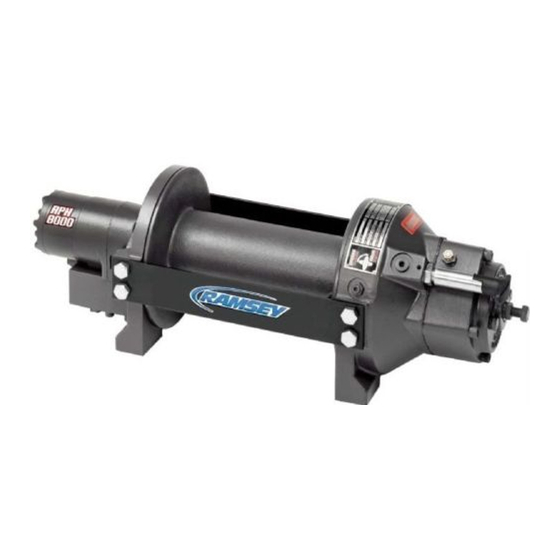
- Page 1 OPERATING, SERVICE AND MAINTENANCE MANUAL MODEL RPH 8000T PLANETARY WINCH INTENDED PURPOSE for RAMSEY RPH 8000T: Vehicle Recovery and Pulling of Loads CAUTION: READ UNDERSTAND THIS MANUAL BEFORE INSTALLATION AND OPERATION OF WINCH. SEE WARNINGS!
-
Page 2: Warranty Information
If the need should arise, warranty procedure is outlined on the back of your self-addressed postage paid warranty card. Please read and fill out the enclosed warranty card and send it to Ramsey Winch Company. If you have any problems with our winch, please follow instructions for prompt service on all warranty claims. Refer to back page for limited warranty. -
Page 3: Winch Mounting
WINCH MOUNTING ESSENTIAL MOUNTING INSTRUCTIONS TO MAINTAIN ALIGNMENT OF PLANETARY WINCH COMPONENTS It is most important that this winch be mounted securely so the three major sections (the motor end, the cable drum and the gear-housing end) are properly aligned. Excessive bushing wear and difficulty in freespooling are usually symptoms of misalignment. -
Page 4: Cable Installation
CABLE INSTALLATION A decal on the top of the end bearing indicates the spooling direction of the cable. Also, a letter “A” or “B” is stamped in the end bearing on the brake end indicating rotation. If the decal is damaged or unreadable, contact Customer Service for additional instructions to determine proper direction. -
Page 5: Hydraulic System Requirements
HYDRAULIC SYSTEM REQUIREMENTS Refer to the performance charts below to properly match your hydraulic system to the winch performance. charts consist of: (1) line pull (LB) first layer vs. working pressure (PSI), and (2) line speed, first layer (FPM) vs. flow (GPM). -
Page 6: Operation
OPERATION The best way to get acquainted with how your winch operates is to make test runs before you actually use it. Plan your test in advance. Remember that you hear your winch, as well as see it operate. Get to recognize the sounds of a light steady pull, a heavy pull, and sounds caused by load jerking or shifting. -
Page 7: Troubleshooting Guide
TROUBLE SHOOTING GUIDE CONDITIONS POSSIBLE CAUSE CORRECTION DRUM WILL NOT ROTATE Winch not mounted squarely, Check mounting. Refer to WINCH AT NO LOAD causing end bearings to bind MOUNTING page 2. up drum. Brake damaged Inspect and replace brake. Gears damaged Inspect and replace damaged gears. -
Page 8: Adjusting The Brake
ADJUSTING THE BRAKE All parts of the oil-cooled automatic safety brake are bathed in oil. When the brake wears to the point that the load begins to drift, the brake can be adjusted as follows: 1. Loosen the lock nut on the adjusting screw (see drawing on page 10). 2. - Page 9 INSTRUCTIONS FOR OVERHAUL OF RAMSEY WINCH MODEL RPH-8,000T DISASSEMBLY Remove breather plug and reducer (item #34 & #39) from winch. Drain oil from winch by removing plug (item # 40). Remove motor (item #35), and coupling (item #31) from winch by unscrewing capscrews (item #24).
- Page 10 Remove tie plates (item #13) from end bearings (items #7 & #8) by unscrewing capscrews (item #18), as shown. Slide motor end bearing (item #7) from drum (item #1) and drum from gear housing end bearing (item #8). Remove input shaft (item #12) from end bearing. Inspect teeth of gear (item #5) for signs of wear. If necessary replace gear by removing snap ring (item #47) and thrust washer (item #50).
-
Page 11: Indicator Light Assembly
Remove brake housing (item #9) from end bearing (item #8) by unscrewing (4) capscrews (item #23). Remove plate (item #12) and light assembly, if present. Remove gasket (item #33), coil spring (item #48), flat spring (item #3), retainer plate (item #11), composition brake discs (item #32) and cam plate (item #4). Remove hub (item #10), and brake shaft (item #55) with plug (item #42)-which is press-fitted in the hub I.D. - Page 12 Remove o-ring (item #36) and bushing (item #15) from motor end bearing (item #7). Press new bushing onto end bearing and dip o-ring in oil and seat into groove of end bearing. Remove seal (item #45) from gear housing end bearing (item #8). Loosen nut (item #27) and remove nylon setscrew (item #22) and remove ring gear (item #6) from gear housing end bearing, if necessary.
- Page 13 Generously apply grease (MOBILITH SHC 007) to teeth of ring gear (item #6), teeth of planet gears in drum (item #1) and to bushing in end bearings (item #7 & #8). Apply grease to teeth of gear (item #5) and to splines of shaft (item #12).
- Page 14 Before installing motor, check brake adjustment (refer to page 7 - ADJUSTING THE BRAKE). Place splined end of coupling (item #31), with spirol pin (item #41) installed, inside of motor end bearing housing (item #7) and slide over splines on end of input shaft. Place o-ring (item #38) around motor pilot. Mount motor (item #35) to end bearing by aligning key on motor shaft with keyway in coupling.
- Page 17 PARTS LIST RPH-8000T WITH MANUAL CLUTCH SHIFTER ITEM QTY. PART NO. DESCRIPTION 234165 DRUM ASS’Y. “Y” 234166 DRUM ASS’Y. “STD.” 276048 SHIFTER ASS’Y. 306035 SPRING-FLAT, BRK. 314017 CAM PLATE-BRAKE “A” ROTATION 314018 CAM PLATE-BRAKE “B” ROTATION 334174 GEAR-OUTPUT, SUN 444084 GEAR-RING 338296 END BEARING-MOTOR...
- Page 19 PARTS LIST RPH-8000T WITH MANUAL CLUTCH SHIFTER AND CLUTCH ENGAGEMENT INDICATOR LIGHT ITEM QTY. PART NO. DESCRIPTION 234165 DRUM ASS’Y. “Y” 234166 DRUM ASS’Y. “STD.” 236020 LIGHT ASS’Y. 276048 SHIFTER ASS’Y. 306035 SPRING-FLAT, BRK. 314017 CAM PLATE-BRAKE “A” ROTATION 314018 CAM PLATE-BRAKE “B”...
- Page 21 PARTS LIST RPH-8,000T WITH AIR-CYLINDER CLUTCH SHIFTER ITEM QTY. PART NO. DESCRIPTION 234165 DRUM ASS'Y. "Y" 234166 DRUM ASS'Y. "STD." 236020 LIGHT ASS'Y. 276049 SHIFTER ASS'Y.-AIR 306035 SPRING-FLAT, BRK. 314017 CAM PLATE-BRAKE “A” ROTATION 314018 CAM PLATE-BRAKE “B” ROTATION 334174 GEAR-OUTPUT, SUN 444084 GEAR-RING...
-
Page 24: Limited Warranty
Manufacturer, of such part that shall appear to the Manufacturer, upon inspection of such part, to have been defective in material or workmanship. This warranty does not obligate RAMSEY WINCH to bear the cost of labor or transportation charges in connection with the replacement or repair of...
Need help?
Do you have a question about the RPH 8000T and is the answer not in the manual?
Questions and answers