Table of Contents
Advertisement
Available languages
Available languages
Quick Links
OPERATING, SERVICE AND
MAINTENANCE MANUAL
CAUTION: READ AND UNDERSTAND THIS MANUAL BEFORE INSTALLATION AND
OPERATION OF WINCH. SEE WARNINGS!
Ramsey Authorized Representative in the Community:
Intended Purpose: Vehicle recovery and pulling of loads
RAMSEY WINCH COMPANY
P. O. Box 581510 - Tulsa OK 74158-1510 USA
Phone: (918) 438-2760 Fax: (918) 438-6688
Visit us at http://www.ramsey.com
(Please contact for regulatory inquiries only. )
English (Original Instructions) . . . . . . . . . . . . . . . 1
Français (Traduction des instructions originales) . . 19
Deutsch (Übersetzung der Originalanleitung) . . . . . 38
Español(Traducción de las instrucciones originales) 56
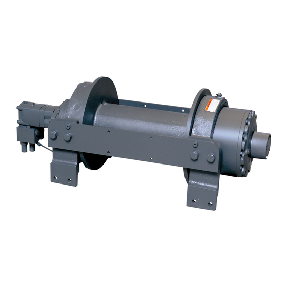
MODEL RPH 133,4
INDUSTRIAL
PLANETARY WINCH
Alura Group BV
P.O. Box 18626
2502 EP The Hague
The Netherlands
Tel: (31) (0) 70 362-4896
Fax: (31) (0) 70 346-7299
OM-914217-0611-A
Advertisement
Chapters
Table of Contents

Subscribe to Our Youtube Channel
Related Manuals for Ramsey Winch RPH 133,4


Summary of Contents for Ramsey Winch RPH 133,4
- Page 1 Français (Traduction des instructions originales) . . 19 MAINTENANCE MANUAL Deutsch (Übersetzung der Originalanleitung) ..38 Español(Traducción de las instrucciones originales) 56 MODEL RPH 133,4 INDUSTRIAL PLANETARY WINCH Intended Purpose: Vehicle recovery and pulling of loads CAUTION: READ AND UNDERSTAND THIS MANUAL BEFORE INSTALLATION AND OPERATION OF WINCH.
- Page 2 Machinery Directive 2006/42/EC aux termes de la directive Machines 2006/42/EC Here with we declare that winch model RPH 133,4 com- Nous déclarons par la présente que le modèle de treuil plies with the following directive provided that the USER RPH 133,4 est conforme à...
-
Page 3: Table Of Contents
TABLE OF CONTENTS SPECIFICATIONS ............1 WARNINGS . -
Page 4: Specifications
SPECIFICATIONS* First Layer Line Pull 133,4 kN (30000 lb) Noise Level 76 db Ambient Temperature Range -28C to 60C (-20F to 140F) Gear Reduction 31:89:1 261 kg (575 lb) Weight (without rope) LAYER OF ROPE 133,4 111,2 95,3 83,3 Line pull per layer 30,000 24,900 21,400... -
Page 5: Hydraulic System Requirements
Refer to the performance charts below to properly match your hydraulic system to the winch performance. The charts consist of: (1) Line Pull first layer kN (lb) vs. Working Pressure bar (PSI). (2) Line Speed, first layer MPM (FPM) vs. flow LPM (GPM). HYDRAULIC SYSTEM REQUIREMENTS Motor spool (open center) control valve Emergency Stop:... -
Page 6: Clutch Operation
Use (8) 5/8 inch diameter grade 5 or better bolts to attach mounting frame to wrecker. ROPE INSTALLATION The RPH 133,4 winch has two tapered pockets cast into the drum. One pocket is for installations with the wire rope wound over the drum. The other pocket is for an underwound wire rope. -
Page 7: Maintenance
MAINTENANCE Adhering to the following maintenance schedule will keep your winch in top condition and performing as it should with a minimum of repair. A. WEEKLY 1. Check the oil level and maintain it to the oil level plug. If oil is leaking out, determine location and repair. 2. -
Page 8: Instructions For Overhaul
INSTRUCTIONS FOR OVERHAUL 1. Drain oil from gear housing item #11 by removing plug item #47 from end bearing. Remove reducer and relief fitting items #41 & #46. If new air cylinder is required, remove air cylinder item #37 from adapter item #4 by removing (4) capscrews item #26. Remove breather vent item #42. - Page 9 3. Remove brake assembly screws item #18 from brake #38a to access (2) mounting screws item #23 attaching brake adapter plate #38d to end bearing item #10. CAUTION: Brake is spring loaded by clutch spring and must be restrained against end bearing as mounting screws item #23 are removed.
- Page 10 5. Pull drum assembly item #1 upward from end bearing item #11. Remove quad-rings item #44 & #45 from grooves in drum bushings. Remove input shaft item #13, clutch spring item #49 and washer item #33 from end bearing item #11. Examine key item #12 and input shaft for signs of wear, replace if damaged.
- Page 11 6. Remove output coupling item #9 and coupling shaft item #7 from end bearing item #11. Examine bearings item #15, pressed in output coupling item #9, for signs of wear. Replace bearings, if necessary, by pressing old bearings from coupling and press new bearings item #15 into each end of output coupling item #9.
- Page 12 8. NOTE: DETERMINE MOUNTING CONFIGURATION OF WINCH (R.H. or L.H. MOUNTED) BEFORE ATTACHING UPRIGHT FRAME TO WINCH, TO ASSURE PARTS ARE MOUNTED TO PROPER SIDE, REFER TO WINCH MOUNTING CONFIGU- RATIONS, STEP 16 PAGE 12. Seat well oiled quad-rings item #44 & #45 into groove of bushing in each end of drum assembly item #1, as shown.
- Page 13 10. Apply RTV sealing compound to ring gear mounting surface of end bearing item #10. Place ring gear onto end bearing, aligning holes in ring gear with holes and gear housing end bearing. Use (2) capscrews to temporarily secure ring gear to end bearing. Place (2) gear carrier assemblies into ring gear meshing carrier gears with ring gear.
- Page 14 12. Align key way of coupling with key on end of input shaft inside end bearing assembly. Slide coupling over end of shaft. Place gasket item #38e into position on motor mounting surface of end bearing item #10. Use (2) screws item #23 to attach adapter plate item #38d to motor end bearing.
-
Page 15: Mounting Configurations
14. Apply Permatex to threads of plug item #47. Thread plug into tapped hole in bottom of gear housing end bearing item #11. Pour approx. 1.2 liters (2.50 pints) of SAE 80W-140 oil into end bearing. Check oil level by removing oil plug noted below. Insert relief fitting item #41 and thread reducer item #46 into end bearing at oil fill hole. - Page 20 ROPE TENSIONER OVERHAUL Refer to the Rope Tensioner Parts Diagram on the following page for the assembly of the Rope Tensioner. The rope tensioner requires an independent, adjustable air supply of between 3,4 bar (50 PSI) and 6,2 bar (90 PSI). Do not operate the winch with the tensioner energized against a bare drum.
- Page 21 PARTS LIST FOR TENSIONER ASSEMBLY ITEM NO. QTY PART NUMBER DESCRIPTION 265021 TENSIONER ASSEMBLY 304186 TENSION BAR 346046 362295 SPACER 365038 TUBE 408227 BRACKET ASSEMBLY 414278 CAPSCREW 3/8-16NC X 3/4 LG HXHD GR5 414545 CAPSCREW 1/2-13NC X 3.5 LG HX HD GR5 418069 NUT 1/2-13NC HX 418080...
- Page 22 Español(Traducción de las instrucciones originales).58 TREUIL À PLANÉTAIRE INDUSTRIEL, MODÈLE RPH 133,4 Utilisation prévue : dépannage de véhicule et traction de charges MISE EN GARDE : LIRE ET COMPRENDRE CE MANUEL AVANT D'INSTALLER ET D'UTILISER LE TREUIL. LIRE LES AVERTISSEMENTS ! RAMSEY WINCH COMPANY P.O.
- Page 23 TABLE DES MATIÈRES CARACTÉRISTIQUES TECHNIQUES ......... . .20 AVERTISSEMENTS .
-
Page 24: Caractéristiques Techniques
CARACTÉRISTIQUES TECHNIQUES* Traction du câble, première couche 133,4 kN (13 608 kg) Niveau sonore 76 dB Plage de températures ambiantes -28 ºC à 60 ºC Poids de démultiplication 31:89:1 (sans le câble) 261 kg COUCHE DE CÂBLE 133,4 111,2 95,3 83,3 Traction du câble, par couche 30,000... -
Page 25: Caractéristiques Du Système Hydraulique
Reportez-vous aux diagrammes de performances ci-dessous pour établir une correspondance entre votre système hydraulique et le fonctionnement de votre treuil. Ces diagrammes sont constitués des éléments suivants : (1) Traction du câble, première couche en kN / Pression de fonctionnement en bars. (2) Vitesse du câble, première couche en m/min / Débit en l/min. -
Page 26: Fonctionnement De L'embrayage
MONTAGE DU CADRE DU TREUIL Utilisez (8) boulons de 15,9 mm de diamètre de grade 5 ou plus pour fixer le cadre de montage sur la dépanneuse. POSE DU CÂBLE Le treuil RPH133,4 comporte deux logements effilés, moulés dans le tambour. L'un d'eux s'emploie pour les installations requérant un enroulement du câble par-dessus le tambour. -
Page 27: Entretien
ENTRETIEN L'observation du calendrier de maintenance suivant vous permettra de maintenir votre treuil en bon état et garantira un fonctionnement avec un minimum de réparations. A. HEBDOMADAIRE 1. Vérifiez le niveau d'huile et maintenez-le au niveau du bouchon. En cas de fuite d'huile, déterminez l'emplacement de la fuite et réparez. -
Page 28: Instructions De Révision
INSTRUCTIONS DE RÉVISION 1. Retirez le bouchon cylindrique (pièce n° 47) du palier d'extrémité pour vidanger l'huile de la boîte d'engrenages (pièce n° 11). Retirez le réducteur n° 41 et le raccord de dégagement n° 46. S'il s'avère nécessaire de changer le cylindre pneumatique, retirez-le de l'adaptateur n° 4 en enlevant les (4) vis d'assemblage n°... - Page 29 3. Retirez les vis n° 18 du frein n° 38a pour accéder aux (2) vis de fixation n° 23 servant à fixer la plaque adaptatrice du frein n° 38d sur le palier d'extrémité n° 10. MISE EN GARDE : le ressort du frein est comprimé...
- Page 30 5. Tirez le tambour n° 1 vers le haut par le palier d'extrémité n° 11. Retirez les joints quad-ring n° 44 et 45 des rainures des bagues du tambour. Retirez l'arbre d'entrée n° 13, le ressort d'embrayage n° 49 et la rondelle n°...
- Page 31 6. Retirez le raccordement de sortie n° 9 et l'arbre de raccordement n° 7 du palier d'extrémité n° 11. Examinez les paliers n° 15 dans le raccordement de sortie n° 9 afin de déceler tout signe d'usure éventuel. Changez-les si besoin est en les sortant et en les remplaçant par des neufs (pièce n° 15) dans chaque extrémité...
- Page 32 8. REMARQUE : DÉTERMINEZ LA CONFIGURATION DE MONTAGE DU TREUIL (MONTAGE DROIT OU GAUCHE) AVANT DE FIXER LE CADRE VERTICAL SUR LE TREUIL, AFIN DE VOUS ASSURER QUE LES PIÈCES SONT MONTÉES DU BON CÔTÉ. RÉFÉREZ-VOUS AUX CONFIGURATIONS DE MONTAGE DU TREUIL, À L'ÉTAPE 16 DE LA PAGE 29. Placez des joints quad-ring bien huilés (pièces n°...
- Page 33 10. Appliquez un mastic d'étanchéité de vulcanisation à la température ambiante sur la surface de montage de la couronne du palier d'extrémité (pièce n° 10). Placez la couronne sur le palier d'extrémité, en alignant les trous de la couronne sur les trous du palier d'extrémité de la boîte d'engrenages. Fixez temporairement la couronne sur le palier d'extrémité...
- Page 34 12. Alignez la rainure de clavette du raccordement avec la clavette à l'extrémité de l'arbre d'entrée à l'intérieur du palier d'extrémité. Faites glisser le raccordement sur l'extrémité de l'arbre. Placez le joint statique (pièce n° 38e) sur la surface de montage du moteur du palier d'extrémité (pièce n° 10). Utilisez (2) vis (pièce n° 23) pour fixer la plaque adaptatrice (pièce n°...
-
Page 35: Configurations De Montage
14. Appliquez du Permatex sur les filets du bouchon (pièce n° 47). Insérez le bouchon dans le trou taraudé au bas du palier d'extrémité de la boîte d'engrenages (pièce n° 11). Versez environ 1,2 l d'huile SAE 80W-140 dans le palier d'extrémité. - Page 40 RÉVISION DU TENDEUR DE CÂBLE Reportez-vous au schéma des pièces du tendeur de câble à la page suivante pour le montage du tendeur de câble. Le tendeur de câble nécessite une alimentation en air indépendante et réglable entre 3,4 bars et 6,2 bars. Ne faites pas fonctionner le treuil alors que le tendeur est sous tension et lorsque le tambour est à...
- Page 41 LISTE DES PIÈCES POUR LE MONTAGE DU TENDEUR N° PIÈCE QTÉ RÉFÉRENCE DESCRIPTION 265021 TENDEUR 304186 BARRE DE TENSION 346046 GOUPILLE 362295 ENTRETOISE 365038 TUBE 408227 SUPPORT 414278 VIS D'ASSEMBLAGE - 3/8-16 NC x 19 mm, TÊTE HEX., GR. 5 414545 VIS D'ASSEMBLAGE 1/2-13 NC x 89 mm, TÊTE HEX., GR.
- Page 42 Verwendungszweck: Fahrzeug-Abschlepp-/Bergungsarbeiten und Ziehen von Lasten ACHTUNG: VOR DER INSTALLATION UND INBETRIEBNAHME DER WINDE MUSS DIESES HANDBUCH GELESEN UND VERSTANDEN WERDEN. SIEHE WARNHINWEISE! RAMSEY WINCH COMPANY P. O. Box 581510 - Tulsa, OK 74158-1510, USA Telefon: +1 (918) 438-2760 Fax: +1 (918) 438-6688 Besuchen Sie uns: http://www.ramsey.com...
- Page 43 INHALTSVERZEICHNIS INHALTSVERZEICHNIS ............39 WARNHINWEISE .
-
Page 44: Warnhinweise
TECHNISCHE DATEN* Seilzugkraft, erste Lage 133,4 kN Lärmpegel 76 db Umgebungstemperaturbereich -28 bis 60 °C Getriebeuntersetzungsgewicht 31:89:1 (ohne Seil) 261 kg SEILLAGE 133,4 111,2 95,3 83,3 Seilzugkraft pro Lage 30,000 24,900 21,400 18,700 * Seilkapazität pro Lage m/min * Seilgeschwindigkeit bei 56,7 l/min * Diese technischen Daten basieren auf dem empfohlenen Drahtseil (20 mm Drahtstärke, Sorte 1960) und einem 195 cm... -
Page 45: Hydraulikanforderungen
Zur richtigen Wahl der Hydraulik für die Leistung der Winde ist auf die folgenden Leistungsdiagramme Bezug zu nehmen. Die Diagramme zeigen: (1) Seilzugkraft (kN), erste Lage im Vergleich zum Arbeitsdruck (bar). (2) Seilgeschwindigkeit, erste Lage (m/min) im Vergleich zur Förderrate (l/min). HYDRAULIKANFORDERUNGEN Wegeventil (Motor-Durchflusssystem) erforderlich Notstopp:... -
Page 46: Kupplungsbetrieb
Mindestdurchmesser von 15,9 mm verwendet werden. INSTALLATION DES SEILS Bei der RPH 133,4 Winde sind zwei konische Taschen in die Seiltrommel gegossen. Eine Tasche wird für Installationen verwendet, bei denen das Drahtseil über die Trommel gewickelt wird. Die andere Tasche wird verwendet, wenn das Seil unter der Trommel durchgeführt wird. -
Page 47: Wartung
WARTUNG Bei Einhaltung der folgenden Wartungsintervalle bleibt die Winde stets im optimalen Zustand mit maximaler Leistung und minimalem Reparaturaufwand. A. WÖCHENTLICH 1. Ölstand prüfen und ggf. bis zur Ölstandsschraube auffüllen. Bei einem Ölleck dessen Lage ausfindig machen und reparieren. Das Überdruckventil an der Oberseite des Getriebekastens überprüfen. Sicherstellen, dass es nicht verstopft ist. -
Page 48: Anleitung Zum Überholen
ANLEITUNG ZUM ÜBERHOLEN 1. Das Öl aus dem Getriebekasten (Nr. 11) ablassen. Dazu den Stopfen (Nr. 47) aus dem Endlager entfernen. Reduzierstück und Überdruckventil (Nr. 41 und 46) entfernen. Wenn der Luftzylinder ersetzt werden muss, den Luftzylinder (Nr. 37) durch Entfernen der vier (4) Kopfschrauben (Nr. 26) vom Adapter (Nr. - Page 49 3. Die Schrauben der Bremsenbaugruppe (Nr. 18) entfernen, um auf die zwei 2 Befestigungsschrauben (Nr. 23) zuzugreifen, die die Bremsenadapterplatte (Nr. 38d) am Endlager (Nr. 10) befestigt. ACHTUNG: Bremse ist durch Kupplungsfeder federbetätigt und muss beim Entfernen der Befestigungsschrauben (Nr. 23) gegen das Endlager zurückgehalten werden. Kupplung (Nr. 8) und Dichtring (Nr.
- Page 50 5. Die Trommelbaugruppe (Nr. 1) nach oben aus dem Endlager (Nr. 11) ziehen. Die Vierlippendichtungen (Nr. 44 und 45) aus den Rillen in den Seiltrommelbuchsen entfernen. Antriebswelle (Nr. 13), Kupplungsfeder (Nr. 49) und Unterlegscheibe (Nr. 33) aus dem Endlager (Nr. 11) entfernen. Den Keil (Nr.
- Page 51 6. Die Abtriebskupplung (Nr. 9) und die Kupplungswelle (Nr. 7) vom Endlager (Nr. 11) ausbauen. Die in die Abtriebskupplung (Nr. 9) gepressten Lager (Nr. 15) auf Anzeichen von Verschleiß untersuchen. Die Lager ggf. ersetzen. Dazu die alten Lager aus der Kupplung stemmen und neue Lager (Nr. 15) an beiden Enden der Abtriebskupplung (Nr.
- Page 52 8. ANMERKUNG: VOR DEM BEFESTIGEN DES AUFRECHTEN RAHMENS AN DER WINDE DIE MONTAGEKONFIGURATION (RECHTS- ODER LINKSSEITIGE MONTAGE) BESTIMMEN, UM SICHERZUSTELLEN, DASS DIE TEILE AUF DER RICHTIGEN SEITE MONTIERT WERDEN (SIEHE MONTAGEKONFIGURATIONEN, SCHRITT 16, AUF SEITE 50). Gut geölte Vierlippendichtungen (Nr. 44 und 45) wie gezeigt in die Buchsenrille an beiden Enden der Seiltrommel (Nr.
- Page 53 10. RTV-Dichtmittel (RTV=bei Raumtemperatur ausvulkanisiert) auf die Montagefläche zwischen Hohlrad und Endlager (Nr. 10) auftragen. Das Hohlrad auf das Endlager stecken und die Löcher im Hohlrad auf die Löcher im Endlager des Getriebekastens ausrichten. Unter Verwendung von zwei (2) Kopfschrauben das Hohlrad vorübergehend am Endlager befestigen.
- Page 54 12. Keilnut der Kupplung auf Keil am Ende der Antriebswelle im Inneren der Endlagerbaugruppe ausrichten. Die Kupplung auf das Wellenende schieben. Den Dichtring (Nr. 38e) auf der Motormontagefläche des Endlagers (Nr. 10) anbringen. Unter Verwendung von zwei (2) Schrauben (Nr. 23) die Adapterplatte (Nr. 38d) am motorseitigen Lager befestigen. Die Kopfschrauben auf 115 Nm festziehen.
-
Page 55: Montagekonfigurationen
14. Auf Gewinde der Verschlussschraube (Nr. 47) Permatex auftragen. Die Verschlussschraube in das Schraubenloch im Boden des Getriebekasten-Endlagers (Nr. 11) schrauben. Ca. 1,2 l SAE 80W-140 Öl in das Endlager füllen. Wie unten gezeigt die Ölstandsschraube entfernen und den Ölstand prüfen. Das Überdruckventil (Nr. - Page 60 SEILSPANNER - ÜBERHOLUNG Für den Zusammenbau des Seilspanners siehe die Teilezeichnung auf der nächsten Seite. Der Seilspanner erfordert eine unabhängige, verstellbare Luftversorgung zwischen 3,4 bar und 6,2 bar. Die Winde nicht betreiben, wenn der Spanner aktiviert ist und gegen eine bloße Trommel anliegt. Die Winde darf nur betrieben werden, falls bei aktiviertem Spanner mindestens eine Wicklung von Seil auf der Trommel aufgespult ist.
- Page 61 TEILELISTE FÜR SPANNERBAUGRUPPE ARTIKEL-NR. ANZ. TEILE-NR. BESCHREIBUNG 265021 SPANNERBAUGRUPPE 304186 SPANNERSTANGE 346046 BOLZEN 362295 ABSTANDHALTER 365038 ROHR 408227 HALTERUNGSBAUGRUPPE 414278 KOPFSCHRAUBE - 3/8-16NC x 19 MM, SECHSKANT, SORTE 5 414545 KOPFSCHRAUBE - 1/2-13NC x 89 MM, SECHSKANT, SORTE 5 418069 MUTTER, 1/2-13NC, SECHSKANT 418080 MUTTER, 5/8-11NC, SECHSKANT...
- Page 62 Español(Traducción de las instrucciones originales). 56 MANTENIMIENTO CABESTRANTE PLANETARIO INDUSTRIAL MODELO RPH 133,4 Uso pretendido para: recuperación de vehículos y arrastre de cargas PRECAUCIÓN: LEER Y ENTENDER ESTE MANUAL ANTES DE INSTALAR Y UTILIZAR EL CABESTRANTE. OBSERVAR LAS ADVERTENCIAS. RAMSEY WINCH COMPANY P.O.
- Page 63 CONTENIDO ESPECIFICACIONES ............58 ADVERTENCIAS .
-
Page 64: Especificaciones
ESPECIFICACIONES* Tracción del cable de la primera capa 133,4 kN (13.608 kg) Nivel sonoro 76 dB Temperatura ambiente De -28º C a 60º C Peso con reducción de 31:89:1 engranajes (sin cable) 261 kg CAPA DE CABLE 133,4 111,2 95,3 83,3 Tracción de cable por capa 30,000... -
Page 65: Requisitos Del Sistema Hidráulico
Consultar los gráficos de funcionamiento que figuran más abajo para ajustar el sistema hidráulico al funcionamiento del cabestrante. Los gráficos son los siguientes: (1) Tracción del cable de la primera capa, en kN, en función de la presión de trabajo, en bares (PSI); (2) Velocidad del cable, primera capa, en MPM, en función del flujo en LPM. REQUISITOS DEL SISTEMA HIDRÁULICO Válvula de control (con ensanche en el centro) de la bobina del motor Parada de emergencia:... -
Page 66: Funcionamiento Del Embrague
MONTAJE DEL BASTIDOR DEL CABESTRANTE Emplear (8) pernos de 15,9 mm de diámetro de clase 5 o mejores para conectar el bastidor de montaje al camión-grúa. INSTALACIÓN DEL CABLE METÁLICO El cabestrante RPH133,4 tiene dos receptáculos cónicos fundidos en el tambor. Uno de los receptáculos es para instalaciones con el cable metálico enrollado en el tambor. -
Page 67: Mantenimiento
MANTENIMIENTO El adherirse al siguiente calendario de mantenimiento hará que el cabestrante esté en excelentes condiciones de funcionamiento y con el mínimo de reparaciones. A. SEMANAL 1. Comprobar el nivel de aceite y mantenerlo hasta el tapón del nivel del aceite. Si existe una fuga de aceite, determinar la ubicación y reparar. -
Page 68: Instrucciones Para Verificar El Cabestrante
INSTRUCCIONES PARA VERIFICAR EL CABESTRANTE 1. Purgar el aceite de la caja de engranajes (elemento núm. 11) sacando el tapón (elemento núm. 47) del cojinete final. Quitar el reductor y la conexión de alivio (elementos núm. 41 y 46). Si se necesita un nuevo cilindro de aire, retirar el cilindro de aire (elemento núm. 37) del adaptador (elemento núm. 4), apartando los (4) tornillos de casquete (elemento núm. - Page 69 3. Retirar los tornillos del conjunto del freno (elemento núm. 18) del freno (elemento núm. 38a) para acceder a los (2) tornillos de montaje (elemento núm. 23) que conectan la placa del adaptador del freno (elemento núm. 38d) al cojinete final (elemento núm. 10). PRECAUCIÓN: el freno se acciona con el muelle del embrague y debe contenerse con el cojinete final cuando se quitan los tornillos de montaje (elemento núm.
- Page 70 5. Tirar del conjunto del tambor (elemento núm. 1) hacia arriba desde el cojinete final (elemento núm. 11). Quitar los anillos cuádruples (elementos núm. 44 y 45) de las ranuras de los cojinetes del tambor. Retirar del cojinete final (elemento núm. 11) el eje de entrada (elemento núm. 13), el muelle del embrague (elemento núm. 49) y la arandela (elemento núm.
- Page 71 6. Retirar el acoplamiento de salida (elemento núm. 9) y el eje del acoplamiento (elemento núm. 7) del cojinete final (elemento núm. 11). Examinar si los cojinetes (elemento núm. 15), colocados con presión sobre el acoplamiento de salida (elemento núm. 9), presentan señales de desgaste. Si es necesario, cambiar los cojinetes; para ello, ejercer presión sobre los cojinetes desgastados para quitarlos del acoplamiento y presionar los nuevos cojinetes (elemento núm.
- Page 72 8. NOTA: DETERMINAR LA CONFIGURACIÓN DE MONTAJE DEL CABESTRANTE (MONTAJE DERECHO O IZQUIERDO) ANTES DE CONECTAR EL BASTIDOR VERTICAL AL CABESTRANTE, PARA ASEGURARSE DE QUE LAS PIEZAS SE MONTAN EN EL LADO CORRECTO. CONSULTAR LAS CONFIGURACIONES DE MONTAJE DEL CABESTRANTE, PASO 16, PÁGINA 69. Asentar los anillos cuádruples bien lubricados (elementos núm.
- Page 73 10. Aplicar compuesto obturador RTV en la superficie de montaje de la corona dentada del cojinete final (elemento núm. 10). Colocar la corona dentada en el cojinete final, alineando los agujeros de ésta con los agujeros y el cojinete final de la caja de engranajes. Usar (2) tornillos de casquete para fijar temporalmente la corona dentada al cojinete final.
- Page 74 12. Alinear la chavetera del acoplamiento con la chaveta en el extremo del eje de entrada dentro del conjunto del cojinete final. Deslizar el acoplamiento sobre el extremo del eje. Poner la empaquetadura (elemento núm. 38) en la posición adecuada de la superficie de montaje del motor del cojinete final (elemento núm.
-
Page 75: Configuraciones De Montaje
14. Aplicar Permatex a las roscas del tapón (elemento núm. 47). Enroscar el tapón en el agujero roscado situado en la parte inferior del cojinete final de la caja de engranajes (elemento núm. 11). Verter unos 1,2 l de aceite SAE 80W-140 en el cojinete final. - Page 80 VERIFICACIÓN DEL TENSADOR DEL CABLE Consulte el diagrama de piezas del tensador del cable que se incluye en la siguiente página para ver cómo se monta el tensador. El tensador del cable necesita que exista una fuente de aire independiente y ajustable de entre 3,4 bares y 6,2 bares.
- Page 81 LISTA DE PIEZAS DEL CONJUNTO DEL TENSADOR NÚM. DE CANTIDAD NÚM. DESCRIPCIÓN ELEMENTO DE PIEZA 265021 CONJUNTO DEL TENSADOR 304186 BARRA DEL TENSADOR 346046 VÁSTAGO 362295 ESPACIADOR 365038 TUBO 408227 CONJUNTO DE SOPORTE 414278 TORNILLO DE CASQUETE 3/8-16NC X 19 mm, CABEZA HEXAGONAL, CLASE 5 414545 TORNILLO DE CASQUETE 1/2-13NC X 89 mm,...
Need help?
Do you have a question about the RPH 133,4 and is the answer not in the manual?
Questions and answers