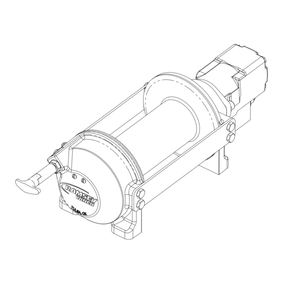
Summary of Contents for Ramsey Winch HD-P800
- Page 1 OPERATING, SERVICE AND MAINTENANCE MANUAL MODEL HD-P8000 PLANETARY WINCH CAUTION: READ AND UNDERSTAND THIS MANUAL BEFORE INSTALLATION AND OPERATION OF WINCH. SEE WARNINGS!
-
Page 2: Table Of Contents
TABLE OF CONTENTS INTRODUCTIONS ..............1 WARRANTY INFORMATION . -
Page 3: Warranty Information
Please read and fill out the enclosed warranty card and send it to Ramsey Winch Company. If you have any problems with your winch, please follow instructions for prompt service on all warranty claims. -
Page 4: Winch Mounting
WINCH MOUNTING ESSENTIAL MOUNTING INSTRUCTIONS TO MAINTAIN ALIGNMENT OF PLANETARY WINCH COMPONENTS: It is most important that this winch be mounted securely so that the three major sections (the motor end, the cable drum, and the gear housing end) are properly aligned. Excessive bushing wear and difficulty in freespooling are usu- ally symptoms of misalignment. -
Page 5: Cable Installation
CABLE INSTALLATION An “A” or “B” decal on the clutch end bearing indicates the spooling direction of the cable. Also, a letter “A” or “B” is stamped in the end bearing on the clutch end indicating rotation direction. If the decal is damaged or unreadable, contact Customer Service for additional instructions to determine proper direction. -
Page 6: Hydraulic System Requirements
HYDRAULIC SYSTEM REQUIREMENTS Refer to the performance charts below to properly match your hydraulic system to the winch performance. The charts consist of: (1) Line Pull first layer (lb.) vs. Working Pressure (PSI) (2) Line Speed, first layer (FPM) vs. flow (GPM) SYSTEM REQUIREMENTS MOTOR SPOOL (OPEN CENTER) CONTROL VALVE REQUIRED 2500 PSI RELIEF VALVE SETTING... -
Page 7: Operation
OPERATION The best way to get acquainted with how your winch operates is to make test runs before you actually use it. Plan your test in advance. Remember, you hear your winch as well as see it operate. Get to recognize the sounds of a light steady pull, a heavy pull, and sounds caused by load jerking or shifting. -
Page 8: Troubleshooting Guide
TROUBLESHOOTING GUIDE CONDITIONS POSSIBLE CAUSE CORRECTION/ACTION DRUM WILL NOT ROTATE Winch not mounted squarely, causing end bearing Check mounting. Refer to Winch Mounting, page 2. AT NO LOAD to bind up Gears damaged Inspect and replace damaged gears DRUM WILL NOT ROTATE Winch not mounted squarely, causing end bearing Check mounting. - Page 9 INSTRUCTIONS FOR OVERHAUL HD-P8000 SERIES WINCH Take note of mounting configurations for proper mounting of parts during re-assembly. Replace all gas- kets, o-rings, and seals during re-assembly. Disconnect tube (item #41) from elbow fittings (items #24) on bottom of end bearing and counterbalance valve (item #42).
- Page 10 Remove retaining rings (items #39 & 46) with screwdriver. Remove brake parts from end bearing. NOTE POSITION OF O-RINGS AND BACKUP RINGS BEFORE REMOVAL. Examine brake discs (items #4) and stators (items #3) for signs of wear, and replace if necessary. Examine o-rings (items #28 and 29) and backup rings (items #31 and 33) in brake piston (item #5), as well as o- ring (item #30) and backup ring (item #32) in backup brake piston (item #6) for signs of wear.
- Page 11 Remove tie plates (items #11) from end bearings by unscrewing capscrews (items #15). Slide motor end bearing (item #8) and drum (item #1) from gear housing end bearing. Remove input shaft (item #10) from end bearing. Inspect shaft and and output sun gear (item #7) for damage and replace if necessary.
- Page 12 Generously apply grease (MOBILITH SHC 007) to teeth of ring gear (item #26), teeth of planet gears in drum (item #1), and to bushing (item #12) in gear housing end bearing. Apply a small amount of grease to base of bushing (item #13) on motor end bearing.
- Page 13 Set winch with gear housing end down on work surface. Install well-oiled o-rings and backup rings into grooves on outside of brake piston and backup brake piston as shown in cross-section A-A below. Piston, backup piston, brake discs and stators must be clean and free of grease and oil. Insert brake discs (item #4) and stators (item #3) into gear end alternating, with stators first and last.
- Page 14 Insert springs (item #40) into pockets in back of brake piston. The two empty pockets should be on opposite sides. Install roll pin (item #35) into new motor coupling below bottom of spline teeth. Insert motor coupling (item #23), engaging it with the discs and the input shaft. Place gasket (item #25) on mounting surface of motor (item #27).
- Page 15 NOTES...


Need help?
Do you have a question about the HD-P800 and is the answer not in the manual?
Questions and answers