Table of Contents
Advertisement
Quick Links
Advertisement
Table of Contents

Related Manuals for Festo CMSH


Summary of Contents for Festo CMSH
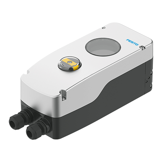
- Page 1 CMSH Positioner Operating instruc- tions 8162856 2021-10 [8162858]...
- Page 2 Translation of the original instructions...
-
Page 3: Table Of Contents
Adjusting position indicator on the CMSH-S-........24... - Page 4 Completion of commissioning of the CMSH-........
-
Page 5: About This Document
About this document About this document Applicable Documents All available documents for the product è www.festo.com/sp. Product version This document refers to the following product versions: Product Version CMSH from hardware revision 1.0.0 from software revision 1.0.0 Tab. 1: Product version The product version can be determined from the product labelling or the local user interface. -
Page 6: Safety
Return to Festo Hazardous substances can endanger the health and safety of personnel and cause damage to the environment. To prevent hazards, the product should only be returned upon explicit request by Festo. – Consult your regional Festo contact. – Complete the declaration of contamination and attach it to the outside of the packaging. -
Page 7: Product Overview
Inspection window for the display actuators in accordance with IEC 60534-6-1 Shaft of the integrated position sensor 4 housing cover screws for displacement/angle measurement (for product variant CMSH-S-...) Pneumatic manifold block Housing bottom part Functional earth (FE), equipotential bonding Festo — CMSH — 2021-10... -
Page 8: Product Variant Cmsh
– 1 digital input for triggering functions – 1 input for an external position sensor Electrical connection, optional module CMSH-…-V2-... – 1 analogue output for position feedback – 2 digital outputs for feedback of the device status and the position limit values –... -
Page 9: Operation And Display
The process views show current process values as well as information on the operating status. The process views are automatically shown on the display when the device is switched on again or if there is no interaction on the user interface for a long time. Festo — CMSH — 2021-10... - Page 10 Tab. 5: Key functions in the process views Status and information in the information area The following status and information can be displayed in the information area of the process views: Symbol Information/status Manual operation Active control signal at the digital input Festo — CMSH — 2021-10...
- Page 11 Active messages are called up when the upper key is pressed in the process views è Key functions. The symbol belonging to the upper operating key indicates the current device status in accordance with NAMUR recommendation NE 107 è Tab. 5 Key functions in Festo — CMSH — 2021-10...
- Page 12 Messages that affect the position sensor, pressure sensor or temperature sensor. Other Other messages Tab. 8: Message groups A detailed description of the messages, possible causes and notes on error elimination can be found in chapter è 8.2 Messages. Festo — CMSH — 2021-10...
- Page 13 – Apply: exit the settings view and accept changes. – Call a routine, action or wizard. – Edit parameters: open settings view. Left key – Change selection: switch to the previous menu entry or selection option. – Reduce parameter values. Festo — CMSH — 2021-10...
- Page 14 The critical action is not executed until the question is confirmed. Pattern Lower key for changing the Lower key for accepting the focused parameter change General principle — Numerical value entry Festo — CMSH — 2021-10...
- Page 15 With step-by-step value entry, a parameter value can be changed with the left and right keys. The value currently stored in the system is displayed in the upper area and the permitted value range in the lower area of the view. Festo — CMSH — 2021-10...
-
Page 16: Function
The CMSH is a digital, electropneumatic positioner. It controls the position of a process valve that is actuated by a pneumatic drive. The CMSH is a 4 … 20 mA loop powered 2-wire device. An additional power supply is therefore not required. - Page 17 – Working port (2) and (4) on the positioner are closed. – Drive holds last position. Tab. 11: Safety position If the power supply is switched on again, the last operating status is effective immediately. Festo — CMSH — 2021-10...
-
Page 18: Assembly
Assembly Assembly Mounting the pneumatic manifold block CAPS on the CMSH-...-V-SD-... Positioner CMSH-...-V-SD-... Pneumatic manifold block CAPS 4 retaining screws Fig. 9: Mounting of pneumatic manifold block CAPS • Fasten the pneumatic manifold block CAPS to the positioner with 4 retaining screws. -
Page 19: Mounting Cmsh-S-Vde1
5.2.2 Mounting CMSH-S-VDE1-… on the semi-rotary drive This chapter describes the attachment of the positioner to a semi-rotary drive in accordance with VDI/VDE 3845-1, IEC 60534-6-2. -
Page 20: Mounting Cmsh-S-Vde2
Shaft adapter 4 M5x8 retaining screws 4 M6x10 retaining screws Fig. 11: Mount CMSH-S-VDE1-… on semi-rotary drive 1. Determine the direction of rotation of the semi-rotary drive. 2. Fasten the mounting adapter to the semi-rotary drive with 4 M5x8 retaining screws. - Page 21 Assembly 5.2.3.1 Mounting CMSH-S-VDE2-… on control plate DADG-FM-F9-VDE2 Semi-rotary drive DFPD-...C-VDE2 Control plate DADG-FM-F9-VDE2 Seals 2 M6x20 retaining screws Housing cover Positioner CMSH-S-VDE2-… Shaft adapter Fig. 12: Mounting CMSH-S-VDE2-… on control plate DADG-FM-F9-VDE2 1. Make sure that the control plate is mounted on the semi-rotary drive.
- Page 22 Assembly 5.2.3.2 Mounting CMSH-S-VDE2-… on adapter plate VABA of valve terminal VTOP Semi-rotary drive DFPD-...C-VDE2 Adapter plate VABA Seals 2 M6x20 retaining screws Housing cover Positioner CMSH-S-VDE2-… Fig. 13: Mounting CMSH-S-VDE2-… on adapter plate VABA of valve terminal VTOP 1. Make sure that the control plate is mounted on the semi-rotary drive.
-
Page 23: Mounting On Linear Drives
Assembly Mounting on linear drives 5.3.1 Mounting CMSH-SE-VDE1-D-… on linear drive DFPI-...-E-NB3 This chapter describes the attachment of the positioner to the linear drive with the adapter kit DADG-AK-F6-A2. Use adapter kit DADG-AK-F6-A2 for linear drive DFPI-...-E-NB3, accessories è 3 Additional information. -
Page 24: Adjusting Position Indicator On The Cmsh-S
Housing cover Positioner CMSH-SE-VDE2-D-… Seals Linear drive DFPI-...-E-NB3VM12 Fig. 15: Mounting CMSH-SE-VDE2-D-… on linear drive DFPI-...-E-NB3VM12 1. Make sure that the control plate is mounted on the linear drive. 2. Unscrew the 4 housing cover screws and remove the housing cover. -
Page 25: Installation
• The fittings, pressure gauge and silencer are not in scope of delivery. • Pressure gauge connections are only available with product variant CMSH-...-V-..• The working port (4) is only available for product variant CMSH-...-D-... and, depending on the version, for product variant CMSH-...-SD-.. - Page 26 Insert seals. – Ensure that the seals are correctly positioned. 3. Select suitable fittings and silencers. Select pressure gauges suitable for the CMSH-...-V-... product variant è 3 Additional information. 4. Screw the fittings, silencers and pressure gauges into the corresponding pneumatic ports.
-
Page 27: Electrical Installation
2. Select a suitable cable connector or insert a blanking plug. – Observe the temperature range. – The cable connector must comply with protection class IP67. – Connecting thread: M20x1.5 für CMSH-...-M20-..., 1/2 NPT for CMSH-...-N12-... 3. Unscrew the housing cover screws. 4. Remove the housing cover. -
Page 28: Wiring Diagram
+81/-82 Digital input for triggering functions Analogue input for external position sensor Tab. 12: Terminals Option: CMSH-…-V2 CMSH-…-V2: additional analogue output and digital input and additional digital outputs. Fig. 19: Wiring diagram CMSH-...-V2 Terminal Designation Function +31/-32 Analogue output for position feedback... -
Page 29: Checking And Setting Parameters In The Menu Views
7.2.1 Menu structure of the menu views The following overview shows all the menus and parameters available in the device in the menu views. Not all menus and parameters are available for all product variants. Festo — CMSH — 2021-10... - Page 30 Operating time Actual position Target position Actuator Diagnosis Armature Activation Reset actuator (counter) Counter Reset armature (counter) Partial stroke test Partial stroke test PST state PST execution Fig. 20: Menu structure of the menu views Festo — CMSH — 2021-10...
- Page 31 Assembly Related Actuator type Actuator function Position sensor type Safety position Device Exhaust position Extension Modules Assembly Related Display Display Language Unit pressure Unit temperature Display Orientation Fig. 21: Menu structure of the menu views Festo — CMSH — 2021-10...
-
Page 32: Guided Setup' Menu
These parameters and other parameters can also be opened and edited via the ‘Settings’ menu è 7.2.4 ‘Settings’ menu. Menu option Reference Language è Language Display Orientation è Display Orientation Actuator type è Actuator type Festo — CMSH — 2021-10... - Page 33 The ‘Actuator type’ parameter defines the drive type to which the positioner is attached. Sine correc- tion can be activated for linear drives with lever kinematics for position detection. Value Description rotary Factory setting linear — linear with lever — Tab. 18: Actuator type Festo — CMSH — 2021-10...
- Page 34 Stroke limitation and tight closing cannot be active simultaneously at one end position. Value Description inactive Factory setting: tight closing inactive. Lower value active Tight closing for upper value of the tight closing limit active. Festo — CMSH — 2021-10...
- Page 35 – After changes in the system structure – After reset to factory settings The permissible stroke range and the controller parameters are determined during initialisation. This involves both end positions being approached in succession independently of the pending setpoint value. Festo — CMSH — 2021-10...
-
Page 36: Operation Mode' Menu
In this operating mode, the setpoint position is entered manually. The selected position is approached at the analogue input independently of the setpoint specification. If the left key is actuated, the setpoint position specification is reduced. If the right key is actuated, the setpoint position specification is increased. Festo — CMSH — 2021-10... -
Page 37: Settings' Menu
7.2.4 ‘Settings’ menu Menu option Description Parameterization Basic parameterisation can be carried out in this area. è 7.2.4.1 Parameterization Control The parameters relevant for the control can be configured in this area. è 7.2.4.2 Control Festo — CMSH — 2021-10... - Page 38 Tab. 27: Parameterization ‘Setpoint’ menu Setpoint direction The ‘Setpoint direction’ parameter defines the relationship between the externally applied setpoint value and the setpoint position. The direction of action is determined independently of the setpoint characteristic curve. Festo — CMSH — 2021-10...
- Page 39 Value Description linear Factory setting: linear characteristic curve 1:25 Equal-percentage characteristic curve 1:33 1:50 25:1 Inverse equal-percentage characteristic curve 33:1 50:1 user defined User-defined characteristic curve Tab. 29: Type of curve Festo — CMSH — 2021-10...
- Page 40 0.0% 0.0 … 98.0% Factory setting: 0.0% 5.0% 0.1 … 98.1% Factory setting: 5.0% … 95.0% 1.9 … 99.9% Factory setting: 98.0% 100.0% 2.0 … 100.0% Factory setting: 100.0% Tab. 30: Interpolation points Festo — CMSH — 2021-10...
- Page 41 Tab. 31: Mode If stroke limitation is active in an end position, the tight-closing function can no longer be activated there. If it is not possible to change the mode, a message appears on the display. Festo — CMSH — 2021-10...
- Page 42 Mode The ‘Mode’ parameter defines the stroke limitation mode. Stroke limitation can be activated at one or both end positions. Festo — CMSH — 2021-10...
- Page 43 The ‘Lower value’ parameter defines the lower value of the stroke limit. This value must be at least 10.0% below the upper stroke limit. Value range Description 0.0 … 90.0% Permissible setting range, factory setting: 0.0% Tab. 35: Lower value Festo — CMSH — 2021-10...
- Page 44 ‘Type of curve’ parameter for the position feedback è ‘Setpoint’ menu. Value Description INAKTIVE Factory setting: no inversion of the position feedback. AKTIVE Inversion of the position feedback. Tab. 38: Curve inversion Festo — CMSH — 2021-10...
- Page 45 ‘User parameters’ menu è 7.2.4.2 Control. Tab. 40: Control mode Deadband The ‘Deadband’ parameter defines the value of the static deadband. The deadband defines a range around the setpoint position within which the closed-loop controller does not react to deviations. Festo — CMSH — 2021-10...
- Page 46 This smoothing can prevent overshooting behaviour in particular. It can lead to an improved settling time for very large drives if the trajectory planning is deactivated. Festo — CMSH — 2021-10...
- Page 47 2 can be configured in this area. DI2 logic è ‘Digital Input 2’ menu DI2 function DI2 target position DO switching mode The switching characteristics of digital outputs 1 and 2 can be defined in this area. è DO switching mode Festo — CMSH — 2021-10...
- Page 48 Initialisation is executed. Hold last TPOS Last setpoint position is held. Hold user TPOS User-defined setpoint position is maintained è ‘Digital input 1’ menu. Close outputs Working port (2) and working port (4) are closed. Festo — CMSH — 2021-10...
- Page 49 Working port (2) and working port (4) are closed. Exhaust output 2 Working port (2) is exhausted. Working port (4) is pressurised. Pressurize out 2 Working port (2) is pressurised. Working port (4) is exhausted. Festo — CMSH — 2021-10...
- Page 50 The high level is output at digital output 1 if the assigned function or the status to be acknowledged is active. Tab. 53: DO1 logic DO1 function The ‘DO1 function’ parameter defines the statuses that are fed back via the digital output. Festo — CMSH — 2021-10...
- Page 51 1. Multiple selections are possible. Option Value Description range Maintenance req. active, Maintenance required inactive Factory setting: inactive Out of spec. active, Outside the specification inactive Factory setting: inactive Festo — CMSH — 2021-10...
- Page 52 Tab. 59: DO2 function DO2 lower value The ‘DO2 lower value’ parameter defines the lower limit value for monitoring the actual position. This value must be reached or undershot in order to generate feedback at digital output 2. Festo — CMSH — 2021-10...
- Page 53 Tab. 62: DO2 state configuration 7.2.4.4 Device Menu option Description Assembly Related The assembly-related parameters can be configured in this area. Actuator type è ‘Assembly Related’ menu Actuator function Position sensor type Safety position Exhaust position Festo — CMSH — 2021-10...
- Page 54 Tab. 64: Actuator type Actuator function The ‘Actuator function’ parameter defines the function of the attached drive. Value Description SINGLEACTING Factory setting for CMSH-...-S-..., cannot be changed DOUBLEACTING Factory setting for CMSH-...-D-..., cannot be changed SINGLEACTING CMSH-...-SD-... : DOUBLEACTING Both SINGLEACTING and DOUBLEACTING can be selected in this var- iant.
- Page 55 Internal potentiometer Factory setting for CMSH-S-... EXTERNAL External potentiometer Factory setting for CMSH-SE-..., cannot be changed Tab. 66: Position sensor type A change to the parameter requires a renewed initialisation è 7.2.5 ‘Initialization’ menu. Safety position The ‘Safety position’ parameter defines the pneumatic initial position of the positioner in the event of electrical power failure.
- Page 56 Factory setting FAHRENHEIT — Tab. 72: Unit temperature Display Orientation The ‘Display Orientation’ parameter defines the display direction of the device. The display can be adjusted in 90° steps. Value Description 0° Factory setting 90° — Festo — CMSH — 2021-10...
-
Page 57: Initialization' Menu
Operation unit The description of the operating unit is displayed in this area. è 7.2.6.2 Operation unit Tab. 74: ‘Identification’ menu 7.2.6.1 Device Device-specific information is displayed in this area. These parameters cannot be changed. Festo — CMSH — 2021-10... -
Page 58: Service' Menu
‘Service’ menu Menu option Description Festo support The link to the Festo Support Portal is displayed in this area in the form of a data matrix code. Signal values The current values/statuses at the analogue inputs, analogue outputs, digital inputs and digital outputs are displayed in this area. -
Page 59: Diagnosis' Menu
è 7.2.8.2 ‘Counter’ menu Partial stroke test The Partial Stroke Test can be executed and its status called up in this area. è 7.2.8.3 ‘Partial stroke test’ menu Tab. 78: ‘Diagnosis’ menu Festo — CMSH — 2021-10... - Page 60 ‘Counter’ menu item and can also be threshold number of reset there è 7.2.8.2 ‘Counter’ menu. changes in direction Factory setting: inactive of drive: 500,000 Festo — CMSH — 2021-10...
- Page 61 Message ID: 1558, there is usually a deviation between the factory setting: external setpoint position specification and request for end posi- the actual position. tions Factory setting: inactive Tab. 79: Activation Festo — CMSH — 2021-10...
- Page 62 – Adjust the parameters for execution of the movement. – Adjust the limit values for the result evaluation and assign them corresponding to the NAMUR status groups. – Execute the reference manoeuvre. A valid reference manoeuvre is a prerequisite for executing a PST. Festo — CMSH — 2021-10...
- Page 63 Fig. 32: Movement with PST execution If the characteristics lie above or below the user-defined thresholds, a message is generated and the Partial Stroke Test is aborted. The following diagram shows the tolerance range of the position limitation: Festo — CMSH — 2021-10...
- Page 64 Tab. 83: Partial Stroke Test configuration parameters Messages about a PST abort Each message is displayed in a separate message view è 4.1.3.3 Message views. The message text is shown in abbreviated form on the display. Festo — CMSH — 2021-10...
- Page 65 1103 P_high 1) Factory setting Tab. 84: Messages about a PST abort Additional messages for Partial Stroke Test If the following criteria are met, a message is generated. The Partial Stroke Test is not aborted. Festo — CMSH — 2021-10...
-
Page 66: Completion Of Commissioning Of The Cmsh
Fact_duration 1) Factory setting Tab. 85: Additional messages for Partial Stroke Test Completion of commissioning of the CMSH-... • Place the housing cover on the positioner and tighten the 4 housing cover screws. – Make sure that the seal is positioned correctly. - Page 67 – With external potentiom- pressure – Drive outside the oper- eter: check attachment ating range of the potenti- position of the potentiom- ometer eter. – Incorrect configuration of – Adjust configuration of the safety position safety position. Festo — CMSH — 2021-10...
- Page 68 – Wait until the PST is fin- PST reference test running manoeuvre ished. – Cancel PST reference manoeuvre manually. – Faulty PST reference – Start PST reference PST: Reference test run necessary manoeuvre manoeuvre. Only possible via EDD and DTM. Festo — CMSH — 2021-10...
- Page 69 – Check supply pressure. Below defined supply – Adjust threshold value if pressure limit shot – Clogged filter necessary. – Too many consumers on – Check filter. – If necessary, install buffer the compressed air line volume. Festo — CMSH — 2021-10...
- Page 70 – Low supply pressure compared to refer- if necessary. – Increased resistance in the – Check supply pressure. ence – Check compressed air compressed air lines – Wear of the positioner lines. – Replace positioner. Festo — CMSH — 2021-10...
- Page 71 – Movement caused by – Check for external forces. when back at starting – If necessary, adjust values position x1 external forces – Increased noise of the of the tolerance target position sensor position (Tol_target). Festo — CMSH — 2021-10...
- Page 72 – Check the mobility of the 1103 PST stopped: Above upper pressure limit upper pressure limit drive or process valve. – Check supply pressure. exceeded – Difficult movement, e.g. due to increased fric- tion – Supply pressure too low Festo — CMSH — 2021-10...
- Page 73 – Check whether the posi- 1298 Initialization failed: Incorrect potentiom- ating range of the potenti- tioner is correctly mounted eter value ometer on the drive. – With external potentiom- eter: check attachment position of the potentiom- eter. Festo — CMSH — 2021-10...
- Page 74 – Drive outside the oper- – Check whether the posi- 1302 Incorrect value: Potentiometer ating range of the potenti- tioner is correctly mounted ometer on the drive. – With external potentiom- eter: check attachment position of the potentiom- eter. Festo — CMSH — 2021-10...
- Page 75 – Incorrect configuration of – Check specification of the the safety position external potentiometer. – Check pneumatic connec- tion. – Check configuration of the safety position. Festo — CMSH — 2021-10...
- Page 76 — tioner in manual mode – Operation of the posi- 1597 Manual operation — tioner in manual mode 1) Corresponds to NAMUR recommendation NE 107 2) Can be changed by the user Tab. 87: Messages Festo — CMSH — 2021-10...
-
Page 77: Disassembly
Safety position: Fail in Place - close working port (2) and working port (4) Mounting position CMSH-... Type of mounting CMSH-...-VDI1-... With accessories in accordance with VDI/VDE 3845 CMSH-...-VDI2-... With accessories in accordance with VDI/VDE 3847-2 Festo — CMSH — 2021-10... -
Page 78: Pneumatic Data
G 1/4 CMSH-...-N14-... 1/4 NPT Connection for pressure gauge CMSH-...-G14-...-V-... G 1/8 CMSH-...-N14-...-V-... 1/8 NPT Tab. 89: Pneumatic data 10.3 Electrical data Analogue input AI Terminals +11/-12 Nominal signal range 4 … 20 mA with HART Festo — CMSH — 2021-10... - Page 79 Tab. 92: Electrical data Digital input DI1/DI2 Terminals DI1 +81/-82 DI2 +85/-86 Characteristics of inputs IEC 61131-2, type 3 (PLC) Input ‘logic 0’ -3 … 5 VDC Input ‘logic 1’ 11 … 30 VDC Reverse-polarity protection Festo — CMSH — 2021-10...
- Page 80 0.2 … 1.5 mm Conductor cross section, flexible 0.2 … 1.5 mm Conductor cross section AWG/kcmil 24 … 16 mm Flexible conductor cross section with wire end sleeve without 0.25 … 1.5 mm plastic sleeve Festo — CMSH — 2021-10...
-
Page 81: Operating And Environmental Conditions
CE marking è www.festo.com/sp 1) All product variants Tab. 96: Operating and environmental conditions 10.5 Materials CMSH-... Material housing Die-cast aluminium, polyester coating Material of the inspection window Material of the screws High-alloy stainless steel Festo — CMSH — 2021-10... - Page 82 Technical data CMSH-... Material of the seals NBR, EPDM, silicone Note on materials RoHS-compliant Tab. 97: Materials CMSH-S-… Material of the shaft High-alloy stainless steel Material of the shaft adapter High-alloy stainless steel Tab. 98: Materials Festo — CMSH — 2021-10...
- Page 84 Copyright: Festo SE & Co. KG 73734 Esslingen Ruiter Straße 82 Deutschland Phone: +49 711 347-0 Internet: © 2021 all rights reserved to Festo SE & Co. KG www.festo.com...
Need help?
Do you have a question about the CMSH and is the answer not in the manual?
Questions and answers