Festo CMSX C-U-F1 Series Operating Instructions Manual
Hide thumbs
Also See for CMSX C-U-F1 Series:
- Operating instructions manual (9 pages) ,
- Translation of the original instructions (7 pages)
Table of Contents
Advertisement
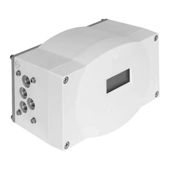
Positioner
CMSX-...-C-U-F1-...
(en) Operating instructions
Original: de
Positioner CMSX
. . . . . . . . . . . . . . . . . . . . . . . . . . . . . . . . . . . . . . . . . . . . . .
For detailed specifications on the product, a complete description and the
declaration of conformity è www.festo.com/sp
1
Layout
1.1 CMSX-S-... (rotary)
1
2
3
3
aA
aJ
aB
1
Housing cover
2
Inspection window for LCD display
3
Housing screws
4
Blanking plug
5
Cable entry with cable connector
6
Mounting thread
Fig. 1
Festo AG & Co. KG
Postfach
73726 Esslingen
Germany
+49 711 347-0
www.festo.com
8059561
1602a
[8059563]
4
5
6
6
9
6
6
6
7
Shaft
8
Mechanical coupling
9
Back plate
aJ
Housing
aA
Pneumatic connections (G1/8)
aB
Earth terminal
1.2 CMSX-SE-... (linear)
3
aJ
9
1
Housing cover
2
Inspection window for LCD display
3
Housing screws
4
Cable entry with cable connector
for external displacement encoder
5
Cable entry with cable connector
for electrical connecting cable
Fig. 2
English
8
1
LCD display
2
Terminal strip 1 (pin 1 ... 14)
3
Terminal strip 2 (pin 1 ... 3)
4
Terminal strip 3 (pin 15, 16)
7
Fig. 3
8
Pin
Designation Description
Terminal strip 1 (pin 1 ... 14)
1
Usp+
2
Usp-
3
Isp+
4
Isp-
5
+24 V DC
6
0 V DC
7
I-
8
I+
9
–
10
ALARM
11
D-OUT1
12
D-OUT2
13
+24 V DC
14
0 V DC
Terminal strip 2 (pin 1 ... 3)
1
0 V DC
2
U+
3
+5 V DC
Terminal strip 3 (pin 15, 16)
15
D-IN+
16
D-IN-
1) Permits split circuits if separate power supply units are used
Fig. 4
1
2
3
4
5
8
7
6
Mounting thread
7
Base plate
8
Housing
9
Pneumatic ports (G1/8)
aJ
Earth terminal
1
7
6
5
4
5
Set key
6
Sub key
7
Add key
8
Earth terminal
Voltage input signal +
Voltage input signal -
Current input signal +
Current input signal -
Operating voltage supply; 24 V DC
Operating voltage supply; 0 V DC
Current output signal -
Current output signal +
Connected at plant to earth terminal
Alarm digital output
Digital output Out 1
Digital output Out 2
Load voltage supply for outputs;
24 V DC
Load voltage supply for outputs; 0 V DC
Operating voltage -
Sensor signal actual value (0 ... 5 V DC)
Operating voltage +
Digital input +
Digital input -
6
6
6
6
6
2
3
Input setpoint value 0 ... 10 V
Input setpoint value
4 ... 20 mA, 0 ... 20 mA
Supply to electronics and
valves
Output actual value 4 ... 20 mA
Do not modify the cable
Alarm output
Status output
Supply to digital outputs
Supply to digital outputs
External displacement
encoder
1)
Control input
1)
Control input
Advertisement
Table of Contents

Related Manuals for Festo CMSX C-U-F1 Series


Summary of Contents for Festo CMSX C-U-F1 Series
- Page 1 1.2 CMSX-SE-... (linear) Positioner CMSX-...-C-U-F1-... Festo AG & Co. KG Postfach 73726 Esslingen Germany +49 711 347-0 Housing cover Mounting thread www.festo.com Inspection window for LCD display Base plate Housing screws Housing (en) Operating instructions 8059561 Cable entry with cable connector...
- Page 2 – Comply with all legal requirements for the handling of hazardous substances and the transport of dangerous goods. For return to Festo è Chapter 2. Fig. 6 – Store the product in a cool, dry, UV- and corrosion-protected environment. En...
- Page 3 Installation CMSX-SE-... (linear) Note Installation should only be conducted by qualified specialized personnel. 5.1 Mechanical Note • Protect the underside of the device from splash water, rain and moisture by selecting an appropriate mounting position. • Observe the direction of rotation of the quarter turn actuator. •...
- Page 4 5.2 Pneumatic Note Note The signal value is unstable when different voltage sources are used for signal Recommendation: Use push-in fittings of type QS-1/8-...-I and tubes of type value and power supply. PUN. • Provide a bridge to the earth terminals of the signal value and the power sup ply pin 4 and pin 6.
- Page 5 Automatic operation OPERAT Auto Commissioning should only be conducted by qualified personnel. level PID controller stopped ACTUAT Stopped For detailed instructions on commissioning è www.festo.com/sp Main menu Current input activated; 4 … 20 mA CONFIG SIGNAL 4-20mA level OPEN Anti-clk...
- Page 6 6.4 Menu structure SP:50.0% VP:50.1% --> 50.0% ACTUAT OPERAT VP:50.1% Running Auto --- 50.0% ACTUAT OPERAT VP:50.1% Stopped Manual ***50.0% VP:50.1% - - MENU - - - - MENU - - - - MENU - - - - MENU - - - - MENU - - - - MENU - - 2 CONFIG...
- Page 7 - - MENU - - 3 PARA •PARA• •PARA• •PARA• •PARA• •PARA• •PARA• •PARA• SPMIN Deadband PID-P PID-D SPMA X PID-P PID-D SPMIN SPMA X DEADBAND 1.0% 100% 100% - - MENU - - 4 CURVE •CURVE• •CURVE• •CURVE• •CURVE• •CURVE•...
- Page 8 Aluminium • Observe the local specifications for environmentally friendly disposal. – Cable connection • Dispose of the product in an environmentally friendly manner. 1) Only in combination with a mounting adapter according to accessories (è www.festo.com/catalogue Fig. 17 Trouble-shooting Note...
Need help?
Do you have a question about the CMSX C-U-F1 Series and is the answer not in the manual?
Questions and answers