Table of Contents
Advertisement
Quick Links
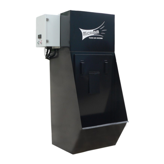
MODEL WC2500
Installation and Operation Manual
Important:
This manual contains specifi c cautionary statements relative to worker safety. Read this manual thoroughly and follow
as directed. It is impossible to list all the hazards of dust control equipment. All persons involved with the equipment or
systems should be instructed how to operate in a safe manner.
Advertisement
Table of Contents

Related Manuals for MICRO-AIR WC2500


Summary of Contents for MICRO-AIR WC2500
- Page 1 MODEL WC2500 Installation and Operation Manual Important: This manual contains specifi c cautionary statements relative to worker safety. Read this manual thoroughly and follow as directed. It is impossible to list all the hazards of dust control equipment. All persons involved with the equipment or...
- Page 2 MICRO AIR WC2500 ® CLEAN AIR SYSTEMS MODEL WC2500 SPECIFICATIONS ASSEMBLY OF UNIT: INPUT VOLTAGE: Determine the location where the air cleaner is to be 208-230V / 460V 60Hz 3 Phase installed. Be sure to allow suffi cient room around the unit...
- Page 3 WC2500 MICRO AIR ® CLEAN AIR SYSTEMS All electrical work must be done by a GENERAL MAINTENANCE: 1. No lubrication is required for the motor because it is a qualifi ed electrician according to local, state permanent pre-lube design. Excessive dirt should be and national codes.
- Page 4 2. Remove the exhaust grille. 3. Place Hepa fi lter support, Hepa fi lter and Hepa fi lter enclosure on top of the WC2500. 4. Align the holes of the Hepa fi lter enclosure with those on the blower cabinet.
- Page 5 1. Remove the bolts and washers from the exhaust grille. 2. Remove the exhaust grille. 3. Place A-frame fi ler housing on top of the WC2500. 4. Align the holes of the A-frame fi lter enclosure with those on the blower cabinet.
- Page 6 MICRO AIR WC2500 ® CLEAN AIR SYSTEMS Offgas Motorized Damper. Inlet Collar. Automatic Fill Valve. Overfl ow Port Low Level Sensor. Drain Port. WC2500 CONNECTION DETAIL...
- Page 7 WC2500 MICRO AIR ® CLEAN AIR SYSTEMS 208/230/460 Volt Wiring Diagram...
- Page 8 MICRO AIR WC2500 ® CLEAN AIR SYSTEMS WC2500 PARTS LIST ITEM PART NO. DESCRIPTION ITEM PART NO. DESCRIPTION P2564 5 HP Motor 34532-01 Sludge Rake 34530-01 Motor Mounting Plate 38295-03 AF Mag Gauge Assy P2566 Blower Housing P7073 MERV 16 After Filter...
Need help?
Do you have a question about the WC2500 and is the answer not in the manual?
Questions and answers