
Subscribe to Our Youtube Channel
Related Manuals for MICRO-AIR OM 3510


Summary of Contents for MICRO-AIR OM 3510
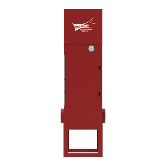
- Page 1 AIR CLEANERS Model OM 3510 OWNER’S MANUAL CAUTION Read complete instructions before operating. Please file for future reference.
-
Page 2: Package Contents
Step 4. Use 3/8” x 2” lag bolts or 3/8” bolts and nuts to secure OM 3510 to structure. *Add 35lb. per charcoal module as option CAUTION: The size and weight of the OM 3510 requires two persons or PACKAGE CONTENTS mechanical means to lift and hold during mounting. - Page 3 AIR FLOW ADJUSTMENT prevent loosening of nuts due to Vibration. The OM 3510 is equipped with variable diameter pulleys on the motor and blower Connect the unit to the oil mist source as explained in Step 6 of to allow the air flow to be adjusted to the installation requirements. The pulleys are set the wall mounting instructions.
-
Page 4: Operation
The pressure switch is also The OM 3510 motor / blower module can be rotated so that exhaust air orientation sensitive. To readjust the switch, remove the hole exits from the side of the unit. - Page 5 UNITS WITH HEPA OR CHARCOAL OP- Place supports (2) in cabinet at a dimension of 13 ¼” and secure with self TIONS FOR OM 3510 tapping screw. On units with optional HEPA or charcoal filters, an adjustable filter track kit is Place track (1) in cabinet so it rests upon supports and ½”...
- Page 6 OM3510 HEPA OR CHARCOAL AS FIRST AND SECOND MAIN FILTERS Place supports (2) in cabinet at a dimension of 24 15/16” and secure with self tapping screws. Place track (1) in cabinet so it rests upon supports and ½” diameter pin is located behind brackets on supports. Place handle (3) on supports so that it rests in notches.
- Page 7 After filling module, discard plastic bag and reinstall fill cover removed in step 2. NOTE: The OM 3510 requires two modules when used as a second main filter and four modules when used as a first and second main filter.
- Page 8 OM3510 OPTIONAL SILENCER INSTALLATION Remove Exhaust Grille from unit as shown in FIG. 10. Slide Silencer over Blower Assembly. Align holes from Silencer with those located on sides of the Blower Assembly. Attach Silencer to Blower Assembly using 3/8” bolt, lockwasher, & flat washer. Center Exhaust Grille over hole in Silencer &...
- Page 9 OM3510 ITEM PART NO. DESCRIPTION ITEM PART NO. DESCRIPTION ITEM PART NO. DESCRIPTION 38071-01 Cabinet Weldment P1710 4.95" Blower Pulley NOT SHOWN 38046-01 Optional Floor Stand 38024-01 Inlet Plenum P1974 5.93" Blower Pulley NOT SHOWN 38050-01 Silencer 38049-01 Wall Bracket (2 ea. required) P1711 6.93"...
- Page 10 OM3510 OM 3510 Wiring Diagram...
- Page 11 OM3510 NOTES:...
-
Page 12: Troubleshooting Chart
OM3510 TROUBLESHOOTING CHART CAUTION: Before disassembling the unit or doing any inspection of the parts, make certain that the power has been cut off and the blower has come to a complete stop. Never run the unit with the access door open or removed. Problem Possible Cause Remedy...
Need help?
Do you have a question about the OM 3510 and is the answer not in the manual?
Questions and answers