Table of Contents
Advertisement
Quick Links
2012/3/62012/3/6
IMBA-G412IS A ATX Mo th e rb o a rd
IEI Te c h n o lo g y Co rp .
MODEL:
IMBA-G412IS A
ATX Mo th e rb o a rd fo r In te l® Co re ™2 Du o /Qu a d CP U,
800/1066/1333 MHz FS B, DDR3, VGA, LAN, S ATA 3Gb /s ,
P CIe x16, P CI, IS A, US B, HD Au d io , Ro HS Co m p lia n t
Re v. 2.00 – 6 Ma rc h , 2012
Us e r Ma n u a l
P a g e i
Advertisement
Table of Contents

Subscribe to Our Youtube Channel
Related Manuals for IEI Technology IMBA-G412ISA-R20


Summary of Contents for IEI Technology IMBA-G412ISA-R20
- Page 1 2012/3/62012/3/6 IMBA-G412IS A ATX Mo th e rb o a rd IEI Te c h n o lo g y Co rp . MODEL: IMBA-G412IS A ATX Mo th e rb o a rd fo r In te l® Co re ™2 Du o /Qu a d CP U, 800/1066/1333 MHz FS B, DDR3, VGA, LAN, S ATA 3Gb /s , P CIe x16, P CI, IS A, US B, HD Au d io , Ro HS Co m p lia n t Us e r Ma n u a l...
- Page 2 ii3/6/2012164 IMBA-G412IS A ATX Mo th e rb o a rd Re vis io n Date Version Changes 6 March, 2012 2.00 Update the version number 20 January, 2012 1.01 Update the BIOS section 26 October, 2010 1.00 Initial release P a g e ii...
- Page 3 2012/1/202012/1/20 IMBA-G412IS A ATX Mo th e rb o a rd Co p yrig h t COP YRIGHT NOTICE The information in this document is subject to change without prior notice in order to improve reliability, design and function and does not represent a commitment on the part of the manufacturer.
-
Page 4: Table Of Contents
iv1/20/2012164 IMBA-G412IS A ATX Mo th e rb o a rd Ta b le o f Co n te n ts 1 INTRODUCTION ......................1 1.1 I ......................2 NTRODUCTION 1.2 B ........................2 ENEFITS 1.3 F ........................3 EATURES 1.4 C ...................... - Page 5 2012/1/202012/1/20 IMBA-G412IS A ATX Mo th e rb o a rd 3.2.11 Power Connector .................... 27 3.2.12 RS-232 Serial Port Connectors ..............28 3.2.13 RS-232/422/485 Serial Port Connector ............29 3.2.14 SATA Drive Connectors ................. 30 3.2.15 SMBus Connector ..................30 3.2.16 SPI Flash Connector ..................
- Page 6 vi1/20/2012164 IMBA-G412IS A ATX Mo th e rb o a rd 4.6 E ........... 58 XTERNAL ERIPHERAL NTERFACE ONNECTION 4.6.1 Audio Connector ....................58 4.6.2 PS/2 Keyboard and Mouse Connection ............59 4.6.3 LAN Connection ....................60 4.6.4 Parallel Device Connection ................61 4.6.5 Serial Device Connection ................
- Page 7 2012/1/202012/1/20 IMBA-G412IS A ATX Mo th e rb o a rd 5.7.2 South Bridge Chipset Configuration .............. 102 5.8 E ........................104 A BIOS OPTIONS ......................106 B TERMINOLOGY ....................... 110 C ONE KEY RECOVERY .................... 114 C.1 O ..............115 ECOVERY NTRODUCTION C.1.1 System Requirement ..................
- Page 8 viii1/20/2012164 IMBA-G412IS A ATX Mo th e rb o a rd Lis t o f Fig u re s Figure 1-1: IMBA-G412ISA ......................2 Figure 1-2: Connectors ........................4 Figure 1-3: Dimensions (mm) ......................5 Figure 1-4: Data Flow Diagram ...................... 6 Figure 3-1: Connectors and Jumpers ..................
- Page 9 2012/1/202012/1/20 IMBA-G412IS A ATX Mo th e rb o a rd Figure 4-2: Remove Protective Cover ..................45 Figure 4-3: CPU Socket Load Plate ..................... 45 Figure 4-4: Insert the Socket LGA775 CPU ................46 Figure 4-5: Cooling Kits ....................... 47 Figure 4-6: Securing the Heat sink to the IMBA-G412ISA ............
- Page 10 x1/20/2012164 IMBA-G412IS A ATX Mo th e rb o a rd Figure C-14: Select a Local Source Drive ................127 Figure C-15: Select a Source Partition from Basic Drive ............127 Figure C-16: File Name to Copy Image to ................128 Figure C-17: Compress Image ....................128 Figure C-18: Image Creation Confirmation ................129 Figure C-19: Image Creation Complete ..................129 Figure C-20: Image Creation Complete ..................129...
- Page 11 2012/1/202012/1/20 IMBA-G412IS A ATX Mo th e rb o a rd Lis t o f Ta b le s Table 1-1: Technical Specifications ....................9 Table 2-1: Packing List ......................... 13 Table 2-2: Optional Items ......................14 Table 3–1: Internal Peripheral Connectors ................18 Table 3–2: External Peripheral Connectors ................
- Page 12 xii1/20/2012164 IMBA-G412IS A ATX Mo th e rb o a rd Table 4-3: Clear BIOS Jumper Settings ..................51 Table 4-4: COM 2 Function Select Jumper Settings ..............52 Table 4-5: CompactFlash® Setup Jumper Settings ..............53 Table 4-6: LCD Voltage Selection Jumper Settings ..............54 Table 4-7: USB Power Select Jumper Settings .................
- Page 13 2012/1/202012/1/20 IMBA-G412IS A ATX Mo th e rb o a rd BIOS Me n u s BIOS Menu 1: Main ........................69 BIOS Menu 2: Advanced ......................70 BIOS Menu 3: CPU Configuration ....................71 BIOS Menu 4: IDE Configuration ....................72 BIOS Menu 5: IDE Master and IDE Slave Configuration ............
-
Page 15: Introduction
2012/1/202012/1/20 IMBA-G412IS A ATX Mo th e rb o a rd Ch a p te r In tro d u c tio n P a g e 1... -
Page 16: Introduction
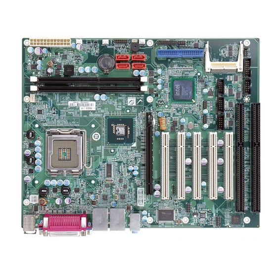
21/20/2012164 IMBA-G412IS A ATX Mo th e rb o a rd 1.1 In tro d u c tio n Figure 1-1: IMBA-G412ISA The IMBA-G412ISA is an ATX motherboard with an 800/1066/1333 MHz front side bus. The LGA775 socket accepts Intel® Core™2 Duo/Quad processors and the motherboard supports two DDR3 DIMMs up to 4.0 GB each (8.0 GB total). -
Page 17: Features
2012/1/202012/1/20 IMBA-G412IS A ATX Mo th e rb o a rd 1.3 Fe a tu re s Some of the IMBA-G412ISA motherboard features are listed below: ATX form factor RoHS compliant LGA775 CPU socket Supports two DDR3 DIMMs ... -
Page 18: Connectors
41/20/2012164 IMBA-G412IS A ATX Mo th e rb o a rd 1.4 Co n n e c to rs The connectors on the IMBA-G412ISA are shown in the figure below. Figure 1-2: Connectors P a g e 4... -
Page 19: Dimensions
2012/1/202012/1/20 IMBA-G412IS A ATX Mo th e rb o a rd 1.5 Dim e n s io n s The main dimensions of the IMBA-G412ISA are shown in the diagram below. Figure 1-3: Dimensions (mm) P a g e 5... -
Page 20: Data Flow
61/20/2012164 IMBA-G412IS A ATX Mo th e rb o a rd 1.6 Da ta Flo w Figure 1-4 shows the data flow between the system chipset, the CPU and other components installed on the motherboard. Figure 1-4: Data Flow Diagram P a g e 6... -
Page 21: Technical Specifications
2012/1/202012/1/20 IMBA-G412IS A ATX Mo th e rb o a rd 1.7 Te c h n ic a l Sp e c ific a tio n s IMBA-G412ISA technical specifications are shown below. S p e c ific a tio n s IMBA-G412IS A Fo rm Fa c to r Socket LGA775 Intel®... - Page 22 81/20/2012164 IMBA-G412IS A ATX Mo th e rb o a rd I/O In te rfa c e One line-in Au d io J a c k One line-out One mic-in One 4-pin wafer for CPU fan Fa n c o n n e c to r Three 3-pin wafer for system fans Two external PS/2 connectors Ke yb o a rd /Mo u s e...
-
Page 23: Table 1-1: Technical Specifications
2012/1/202012/1/20 IMBA-G412IS A ATX Mo th e rb o a rd P h ys ic a l S p e c ific a tio n s 305 mm x 244 mm Dim e n s io n s 1200 g / 750 g We ig h t (Gro s s /Ne t) Table 1-1: Technical Specifications P a g e 9... -
Page 24: Packing List
101/20/2012164 IMBA-G412IS A ATX Mo th e rb o a rd Ch a p te r P a c kin g Lis t P a g e 10... -
Page 25: Anti Static Precautions
2012/1/202012/1/20 IMBA-G412IS A ATX Mo th e rb o a rd 2.1 An ti-s ta tic P re c a u tio n s WARNING! Static electricity can destroy certain electronics. Make sure to follow the ESD precautions to prevent damage to the product, and injury to the user. -
Page 26: Packing List
121/20/2012164 IMBA-G412IS A ATX Mo th e rb o a rd 2.3 P a c kin g Lis t NOTE: If any of the components listed in the checklist below are missing, do not proceed with the installation. Contact the IEI reseller or vendor the IMBA-G412ISA was purchased from or contact an IEI sales representative directly by sending an email to sales@iei.com.tw. -
Page 27: Optional Items
2012/1/202012/1/20 IMBA-G412IS A ATX Mo th e rb o a rd Qu a n tity Ite m a n d P a rt Nu m b e r Im a g e Utility CD Quick Installation Guide Table 2-1: Packing List 2.4 Op tio n a l Ite m s The following are optional components which may be separately purchased: Ite m a n d P a rt Nu m b e r... -
Page 28: Table 2-2: Optional Items
141/20/2012164 IMBA-G412IS A ATX Mo th e rb o a rd Ite m a n d P a rt Nu m b e r Im a g e ATA 66/100 flat cable (P/N: 32200-000052-RS) USB cable (P/N: CB-USB02-RS SATA power cable (P/N: 32102-000100-200-RS) DVI output SDVO card (P/N: SDVO-100DVI-R10) -
Page 29: Connectors
2012/1/202012/1/20 IMBA-G412IS A ATX Mo th e rb o a rd Ch a p te r Co n n e c to rs P a g e 15... -
Page 30: Peripheral Interface Connectors
161/20/2012164 IMBA-G412IS A ATX Mo th e rb o a rd 3.1 P e rip h e ra l In te rfa c e Co n n e c to rs This chapter details all the jumpers and connectors. 3.1.1 La yo u t The figure below shows all the connectors and jumpers. -
Page 31: Peripheral Interface Connectors
2012/1/202012/1/20 IMBA-G412IS A ATX Mo th e rb o a rd 3.1.2 P e rip h e ra l In te rfa c e Co n n e c to rs The table below lists all the connectors on the board. Co n n e c to r Typ e La b e l... -
Page 32: External Interface Panel Connectors
181/20/2012164 IMBA-G412IS A ATX Mo th e rb o a rd Co n n e c to r Typ e La b e l SPI Flash 8-pin header JSPI1 TPM connector 20-pin header TPM1 USB connectors 8-pin header USB3, USB4 Table 3–1: Internal Peripheral Connectors 3.1.3 Exte rn a l In te rfa c e P a n e l Co n n e c to rs The table below lists the connectors on the external I/O panel. -
Page 33: Cpu Fan Connector
2012/1/202012/1/20 IMBA-G412IS A ATX Mo th e rb o a rd Figure 3-2: Audio Connector Location Description Description MIC_L Audio GND MIC_R FP_AUO_DETECT LINE_R F_SENSE LINE_L Table 3-3: Audio Connector Pinouts 3.2.2 CP U Fa n Co n n e c to r CN La b e l: CP U_FAN1 4-pin wafer... -
Page 34: System Fan Connectors
201/20/2012164 IMBA-G412IS A ATX Mo th e rb o a rd Figure 3-3: CPU Fan Connector Location Description +12 V Fan In Fan Control Table 3-4: CPU Fan Connector Pinouts 3.2.3 S ys te m Fa n Co n n e c to rs CN La b e l: NB_FAN1, S YS _FAN1 a n d S YS _FAN2 3-pin wafer... -
Page 35: Cpu Power Input Connector
2012/1/202012/1/20 IMBA-G412IS A ATX Mo th e rb o a rd Description FANIN2 +12 V Table 3-5: System Fan Connector Pinouts (SYS_FAN1) Description +12 V Table 3-6: System Fan Connector Pinouts (SYS_FAN2 and SYS_FAN3) 3.2.4 CP U P o we r In p u t Co n n e c to r CN La b e l: CP U12V1 4-pin connector... -
Page 36: Digital I/O Connector
221/20/2012164 IMBA-G412IS A ATX Mo th e rb o a rd 3.2.5 Dig ita l I/O Co n n e c to r CN La b e l: DIO1 10-pin header CN Typ e : CN Lo c a tio n : See Figure 3-6 CN P in o u ts : See Table 3-8... -
Page 37: Ide Connector
2012/1/202012/1/20 IMBA-G412IS A ATX Mo th e rb o a rd CN Lo c a tio n : See Figure 3-7 See Table 3-9 CN P in o u ts : The front panel connector connects to the indicator LEDs and buttons on the computer's front panel. -
Page 38: Figure 3-8: Ide Connector Location
241/20/2012164 IMBA-G412IS A ATX Mo th e rb o a rd The IDE connector can connect to an IDE hard drive or optical device. Figure 3-8: IDE Connector Location Description Description RESET# GROUND DATA 7 DATA 8 DATA 6 DATA 9 DATA 5 DATA 10 DATA 4... -
Page 39: Infrared Interface Connector
2012/1/202012/1/20 IMBA-G412IS A ATX Mo th e rb o a rd 3.2.8 In fra re d In te rfa c e Co n n e c to r CN La b e l: 5-pin header (1x5) CN Typ e : CN Lo c a tio n : See Figure 3-9 CN P in o u ts :... -
Page 40: Pcie Power Input Connector
261/20/2012164 IMBA-G412IS A ATX Mo th e rb o a rd The DIMM slots are for DDR3 DIMM memory modules. Figure 3-10: Memory Card Slot Location 3.2.10 P CIe P o we r In p u t Co n n e c to r CN La b e l: P NC1 3-pin wafer (1x3) -
Page 41: Power Connector
2012/1/202012/1/20 IMBA-G412IS A ATX Mo th e rb o a rd Description VCC +5 V VCC +12 V Table 3-12: PCIe Power Input Connector Pinouts 3.2.11 P o we r Co n n e c to r CN La b e l: P WR2 24-pin connector CN Typ e :... -
Page 42: Serial Port Connectors
281/20/2012164 IMBA-G412IS A ATX Mo th e rb o a rd Description Description +12V +12V +3.3V Table 3-13: Power Connector Pinouts 3.2.12 RS -232 S e ria l P o rt Co n n e c to rs CN La b e l: COM3, COM4, COM5, COM6 10-pin box header CN Typ e :... -
Page 43: Rs-232/422/485 Serial Port Connector
2012/1/202012/1/20 IMBA-G412IS A ATX Mo th e rb o a rd Description NCTS NDTR Table 3-14: Serial Port Connector Pinouts 3.2.13 RS -232/422/485 S e ria l P o rt Co n n e c to r CN La b e l: COM2 14-pin box header CN Typ e :... -
Page 44: Sata Drive Connectors
301/20/2012164 IMBA-G412IS A ATX Mo th e rb o a rd Description Description Table 3-15: RS-232/422/485 Serial Port Connector Pinouts 3.2.14 S ATA Drive Co n n e c to rs CN La b e l: S ATA1, S ATA2, S ATA3, S ATA4 7-pin SATA drive connectors CN Typ e : CN Lo c a tio n :... -
Page 45: Spi Flash Connector
2012/1/202012/1/20 IMBA-G412IS A ATX Mo th e rb o a rd Figure 3-16: SMBus Connector Locations Description SMBDATA SMBCLK Table 3-16: SMBus Connector Pinouts 3.2.16 S P I Fla s h Co n n e c to r CN La b e l: J S P I1 8-pin header CN Typ e :... -
Page 46: Tpm Connector
321/20/2012164 IMBA-G412IS A ATX Mo th e rb o a rd Figure 3-17: SPI Flash Connector Description Description +3.3V CLOCK Table 3-17: SPI Flash Connector 3.2.17 TP M Co n n e c to r CN La b e l: TP M1 20-pin header (2x10) CN Typ e :... -
Page 47: Usb Connectors
2012/1/202012/1/20 IMBA-G412IS A ATX Mo th e rb o a rd Figure 3-18: TPM Connector Pinout Location Description Description TPMCLK LFRAME- PCIRST4- +5 V LAD3 LAD2 LAD0 LAD1 SMBCLK_MAIN SMBDATA_MAIN +3.3 V SERIRQ CLKRUN- +3.3 V LDRQ- Table 3-18: TPM Connector Pinouts 3.2.18 US B Co n n e c to rs CN La b e l: US B3, US B4... -
Page 48: External Peripheral Interface Connector Panel
341/20/2012164 IMBA-G412IS A ATX Mo th e rb o a rd Figure 3-19: USB Connector Pinout Locations Description Description USBP4/6# USBP5/7 USBP4/6 USBP5/7# Table 3-19: USB Port Connector Pinouts 3.3 Exte rn a l P e rip h e ra l In te rfa c e Co n n e c to r P a n e l The figure below shows the external peripheral interface connector (EPIC) panel. -
Page 49: Audio Connectors
2012/1/202012/1/20 IMBA-G412IS A ATX Mo th e rb o a rd 3.3.1 Au d io Co n n e c to rs CN La b e l: AUDIO1 Audio jacks CN Typ e : CN Lo c a tio n : See Figure 3-20 The audio jacks connect to external audio devices. -
Page 50: Lan Connectors
361/20/2012164 IMBA-G412IS A ATX Mo th e rb o a rd Figure 3-22: PS/2 Pinout and Configuration Description Description KB_DATA MS_CLK KB_CLK KB_GND MS_DATA KB_GND Table 3-20: Keyboard Connector Pinouts 3.3.3 LAN Co n n e c to rs CN La b e l: LAN1, LAN2 RJ-45 CN Typ e :... -
Page 51: Parallel Port Connector
2012/1/202012/1/20 IMBA-G412IS A ATX Mo th e rb o a rd Description Description LAN1/2_MDI0+ LAN1/2_MDI3- LAN1/2_MDI0- LAN1/2_MDI1+ LAN1/2_LINK100 LAN1/2_MDI1- LAN1/2_LINK1000 LAN1/2_MDI2+ LAN1/2_LED0 LAN1/2_MDI2- 3.3 V Table 3-21: LAN Pinouts 3.3.4 P a ra lle l P o rt Co n n e c to r CN La b e l: 3IN1_DS UB1A CN Typ e :... -
Page 52: Serial Port Connector (Com1)
381/20/2012164 IMBA-G412IS A ATX Mo th e rb o a rd Figure 3-23: Parallel Port Connector Location 3.3.5 S e ria l P o rt Co n n e c to r (COM1) CN La b e l: 3IN1_DS UB1B (COM1) DB-9 Male CN Typ e : See Figure 3-20... -
Page 53: Usb Connectors
2012/1/202012/1/20 IMBA-G412IS A ATX Mo th e rb o a rd 3.3.6 US B Co n n e c to rs CN La b e l: US B1, US B2 USB port CN Typ e : CN Lo c a tio n : See Figure 3-20 CN P in o u ts : See Table 3-24... -
Page 54: Table 3-25: Vga Connector Pinouts
401/20/2012164 IMBA-G412IS A ATX Mo th e rb o a rd Description Description GREEN BLUE CRT_PLUG# VGAVCC DDC DAT HSYNC VSYNC DDCCLK Table 3-25: VGA Connector Pinouts P a g e 40... -
Page 55: Installation
2012/1/202012/1/20 IMBA-G412IS A ATX Mo th e rb o a rd Ch a p te r In s ta lla tio n P a g e 41... -
Page 56: Anti - Static Precautions
421/20/2012164 IMBA-G412IS A ATX Mo th e rb o a rd 4.1 An ti-s ta tic P re c a u tio n s WARNING: Failure to take ESD precautions during the installation of the IMBA-G412ISA result permanent damage IMBA-G412ISA and severe injury to the user. Electrostatic discharge (ESD) can cause serious damage to electronic components, including the IMBA-G412ISA. - Page 57 2012/1/202012/1/20 IMBA-G412IS A ATX Mo th e rb o a rd WARNING: The installation instructions described in this manual should be carefully followed in order to prevent damage to the components and injury to the user. Before and during the installation please DO the following: ...
-
Page 58: Basic Installation
441/20/2012164 IMBA-G412IS A ATX Mo th e rb o a rd 4.3 Ba s ic In s ta lla tio n This section outlines the parts that must be installed for the system to function correctly. 4.3.1 CP U In s ta lla tio n NOTE: To enable Hyper-Threading, the CPU and chipset must both support it. -
Page 59: Figure 4-2: Remove Protective Cover
2012/1/202012/1/20 IMBA-G412IS A ATX Mo th e rb o a rd WARNING: DO NOT touch the pins at the bottom of the CPU. When handling the CPU, only hold it on the sides. S te p 1: Remove the protective cover. The black protective cover can be removed by pulling up on the tab labeled "Remove". -
Page 60: Figure 4-4: Insert The Socket Lga775 Cpu
461/20/2012164 IMBA-G412IS A ATX Mo th e rb o a rd Inspect the CPU socket. Make sure there are no bent pins and make sure the S te p 3: socket contacts are free of foreign material. If any debris is found, remove it with compressed air. -
Page 61: Cooling Kit Installation
2012/1/202012/1/20 IMBA-G412IS A ATX Mo th e rb o a rd 4.3.2 Co o lin g Kit In s ta lla tio n WARNING: DO NOT use the original Intel® heat sink and fan. A proprietary one is recommended. Figure 4-5: Cooling Kits The cooling kit can be bought from IEI. -
Page 62: Figure 4-6: Securing The Heat Sink To The Imba-G412Isa
481/20/2012164 IMBA-G412IS A ATX Mo th e rb o a rd Mount the cooling kit. Gently place the cooling kit on top of the CPU. Make S te p 3: sure the four threaded screws on the corners of the cooling kit properly pass through the predrilled holes on the bottom of the PCB. -
Page 63: Dimm Installation
2012/1/202012/1/20 IMBA-G412IS A ATX Mo th e rb o a rd 4.3.3 DIMM In s ta lla tio n To install a DIMM, please follow the steps below and refer to Figure 4-7. Figure 4-7: DIMM Installation S te p 1: Open the DIMM socket handles. -
Page 64: Jumper Settings
501/20/2012164 IMBA-G412IS A ATX Mo th e rb o a rd 4.4 J u m p e r S e ttin g s NOTE: A jumper is a metal bridge used to close an electrical circuit. It consists of two or three metal pins and a small metal clip (often protected by a plastic cover) that slides over the pins to connect them. -
Page 65: Clear Cmos Jumper
2012/1/202012/1/20 IMBA-G412IS A ATX Mo th e rb o a rd J u m p e r Lo c a tio n : See Figure 4-8 The AT Power Select jumper specifies the systems power mode as AT or ATX. Setting Description Open... -
Page 66: Com 2 Function Select Jumper
521/20/2012164 IMBA-G412IS A ATX Mo th e rb o a rd Figure 4-9: Clear BIOS Jumper Location 4.4.3 COM 2 Fu n c tio n S e le c t J u m p e r J u m p e r La b e l: J P 4 6-pin header J u m p e r Typ e :... -
Page 67: Compactflash® Setup
2012/1/202012/1/20 IMBA-G412IS A ATX Mo th e rb o a rd 4.4.4 Co m pa c tFla s h ® S e tu p J u m p e r La b e l: J P 2 2-pin header J u m p e r Typ e : See Table 4-5 J u m p e r S e ttin g s : J u m p e r Lo c a tio n :... -
Page 68: Usb Power Select Jumpers
541/20/2012164 IMBA-G412IS A ATX Mo th e rb o a rd Setting Description Short 1-2 +5.0 V Short 2-3 +3.3 V Table 4-6: LCD Voltage Selection Jumper Settings Figure 4-12: LCD Voltage Selection Jumper Location 4.4.6 US B P o we r S e le c t J u m p e rs J u m p e r La b e l: US BP W12, US BP 34 J u m p e r Typ e :... -
Page 69: Internal Peripheral Device Connections
2012/1/202012/1/20 IMBA-G412IS A ATX Mo th e rb o a rd Figure 4-13: USB Power Select Jumper Location 4.5 In te rn a l P e rip h e ra l De vic e Co n n e c tio n s This section outlines the installation of peripheral devices to the onboard connectors. -
Page 70: Figure 4-14: Sata Drive Cable Connection
561/20/2012164 IMBA-G412IS A ATX Mo th e rb o a rd Figure 4-14: SATA Drive Cable Connection S te p 3: Connect the cable to the SATA disk. Connect the connector on the other end of the cable to the connector at the back of the SATA drive. See Figure 4-15. S te p 4: Connect the SATA power cable. -
Page 71: Dual Rs-232 Cable With Slot Bracket
2012/1/202012/1/20 IMBA-G412IS A ATX Mo th e rb o a rd Figure 4-15: SATA Power Drive Connection 4.5.2 Du a l RS -232 Ca b le with S lo t Bra c ke t The dual RS-232 cable slot connector consists of two connectors attached to two independent cables. -
Page 72: External Peripheral Interface Connection
581/20/2012164 IMBA-G412IS A ATX Mo th e rb o a rd Figure 4-16: Dual RS-232 Cable Installation Secure the bracket. The dual RS-232 connector has two D-sub 9 male S te p 3: connectors secured on a bracket. To secure the bracket to the chassis please refer to the reference material that came with the chassis. -
Page 73: Ps/2 Keyboard And Mouse Connection
2012/1/202012/1/20 IMBA-G412IS A ATX Mo th e rb o a rd Plug the audio plugs into the audio jacks. Plug the audio plugs into the audio S te p 2: jacks. If the plugs on your speakers are different, an adapter will need to be used to plug them into the audio jacks. -
Page 74: Lan Connection
601/20/2012164 IMBA-G412IS A ATX Mo th e rb o a rd Insert the keyboard/mouse connector. Insert a PS/2 keyboard or mouse S te p 2: connector into the appropriate PS/2 connector on the external peripheral interface connector. See Figure 4-18. Figure 4-18: PS/2 Keyboard/Mouse Connector 4.6.3 LAN Co n n e c tio n There are two external RJ-45 LAN connectors. -
Page 75: Parallel Device Connection
2012/1/202012/1/20 IMBA-G412IS A ATX Mo th e rb o a rd Figure 4-19: LAN Connection S te p 3: Insert the LAN cable RJ-45 connector. Once aligned, gently insert the LAN cable RJ-45 connector into the on-board RJ-45 connector. S te p 0: 4.6.4 P a ra lle l De vic e Co n n e c tio n The IMBA-G412ISA has a single female DB-25 connector on the external peripheral interface panel for parallel devices. -
Page 76: Serial Device Connection
621/20/2012164 IMBA-G412IS A ATX Mo th e rb o a rd Figure 4-20: Parallel Device Connector Secure the connector. Secure the DB-25 connector to the external interface by S te p 3: tightening the two retention screws on either side of the connector. 4.6.5 S e ria l De vic e Co n n e c tio n The IMBA-G412ISA has one male DB-9 connectors on the external peripheral interface panel for a serial device. -
Page 77: Usb Device Connection
2012/1/202012/1/20 IMBA-G412IS A ATX Mo th e rb o a rd Figure 4-21: Serial Device Connector Secure the connector. Secure the serial device connector to the external S te p 3: interface by tightening the two retention screws on either side of the connector. S te p 0: 4.6.6 US B De vic e Co n n e c tio n The external USB Series "A"... -
Page 78: Vga Monitor Connection
641/20/2012164 IMBA-G412IS A ATX Mo th e rb o a rd Figure 4-22: USB Connector 4.6.7 VGA Mo n ito r Co n n e c tio n The IMBA-G412ISA has a single female DB-15 connector on the external peripheral interface panel. -
Page 79: Software Installation
2012/1/202012/1/20 IMBA-G412IS A ATX Mo th e rb o a rd Figure 4-23: VGA Connector S te p 4: Secure the connector. Secure the DB-15 VGA connector from the VGA monitor to the external interface by tightening the two retention screws on either side of the connector. -
Page 80: Bios
661/20/2012164 IMBA-G412IS A ATX Mo th e rb o a rd Ch a p te r BIOS P a g e 66... -
Page 81: Introduction
2012/1/202012/1/20 IMBA-G412IS A ATX Mo th e rb o a rd 5.1 In tro d u c tio n The BIOS is programmed onto the BIOS chip. The BIOS setup program allows changes to certain system settings. This chapter outlines the options that can be changed. 5.1.1 Sta rtin g S e tu p The AMI BIOS is activated when the computer is turned on. -
Page 82: Getting Help
681/20/2012164 IMBA-G412IS A ATX Mo th e rb o a rd Ke y Fu n c tio n F2/F3 key Change color from total 3 colors. F2 to select color forward Save all the CMOS changes, only for Main Menu Table 5-1: BIOS Navigation Keys 5.1.3 Ge ttin g He lp When F1 is pressed a small help window describing the appropriate keys to use and the... -
Page 83: Main
2012/1/202012/1/20 IMBA-G412IS A ATX Mo th e rb o a rd 5.2 Ma in The Main BIOS menu (BIOS Menu 1) appears when the BIOS Setup program is entered. The Main menu gives an overview of the basic system information. BIOS SETUP UTILITY Main Advanced... -
Page 84: Advanced
701/20/2012164 IMBA-G412IS A ATX Mo th e rb o a rd The System Overview field also has two user configurable fields: S ys te m Tim e [xx:xx:xx] Use the System Time option to set the system time. Manually enter the hours, minutes and seconds. -
Page 85: Cpu Configuration
2012/1/202012/1/20 IMBA-G412IS A ATX Mo th e rb o a rd 5.3.1 CP U Co n fig u ra tio n Use the CPU Configuration menu (BIOS Menu 3) to view detailed CPU specifications and configure the CPU. BIOS SETUP UTILITY Advanced Configure advanced CPU Settings Module Version:3F.15... -
Page 86: Bios Menu 4: Ide Configuration
721/20/2012164 IMBA-G412IS A ATX Mo th e rb o a rd BIOS SETUP UTILITY Advanced IDE Configuration Options Disabled ATA/IDE Configuration [Enhanced] Compatible Configure SATA as [IDE] Enhanced Configure SATA Channels [Before PATA] > Primary IDE Master : [Not Detected] ... -
Page 87: Ide Master, Ide Slave
2012/1/202012/1/20 IMBA-G412IS A ATX Mo th e rb o a rd Co n fig u re S ATA Ch a n n e ls [Be fo re PATA] Use the Configure SATA Channels option to determine how SATA channels and PATA channels are ordered. -
Page 88: Bios Menu 5: Ide Master And Ide Slave Configuration
741/20/2012164 IMBA-G412IS A ATX Mo th e rb o a rd BIOS SETUP UTILITY Advanced Primary IDE Master Select the type of device connected to the system. Device :Not Detected Type [Auto] LBA/Large Mode [Auto] Block (Multi-Sector Transfer) [Auto] ... - Page 89 2012/1/202012/1/20 IMBA-G412IS A ATX Mo th e rb o a rd 32Bit Data Transfer: Enables 32-bit data transfer. Typ e [Au to ] Use the Type BIOS option select the type of device the AMIBIOS attempts to boot from after the Power-On Self-Test (POST) is complete.
- Page 90 761/20/2012164 IMBA-G412IS A ATX Mo th e rb o a rd Blo c k (Mu lti S e c to r Tra n s fe r) [Au to ] Use the Block (Multi Sector Transfer) to disable or enable BIOS to auto detect if the device supports multi-sector transfers.
- Page 91 2012/1/202012/1/20 IMBA-G412IS A ATX Mo th e rb o a rd SWDMA0 Single Word DMA mode 0 selected with a maximum data transfer rate of 2.1MBps Single Word DMA mode 1 selected with a maximum data SWDMA1 transfer rate of 4.2MBps ...
- Page 92 781/20/2012164 IMBA-G412IS A ATX Mo th e rb o a rd S .M.A.R.T [Au to ] Use the S.M.A.R.T option to auto-detect, disable or enable Self-Monitoring Analysis and Reporting Technology (SMART) on the drive on the specified channel. S.M.A.R.T predicts impending drive failures.
-
Page 93: Super Io Configuration
2012/1/202012/1/20 IMBA-G412IS A ATX Mo th e rb o a rd 5.3.3 S u p e r IO Co n fig u ra tio n Use the Super IO Configuration menu (BIOS Menu 6) to set or change the configurations for the serial ports. BIOS SETUP UTILITY Advanced Configure F81865F Super IO Chipset... - Page 94 801/20/2012164 IMBA-G412IS A ATX Mo th e rb o a rd IRQ3 Serial port 1 IRQ address is IRQ3 S e ria l P o rt2 Ad d re s s [2F8] Use the Serial Port2 Address option to select the Serial Port 2 base address. ...
- Page 95 2012/1/202012/1/20 IMBA-G412IS A ATX Mo th e rb o a rd Serial port 3 IRQ address is 10 EFAULT S e ria l P o rt4 Ad d re s s [2E8] Use the Serial Port4 Address option to select the Serial Port 4 base address. ...
- Page 96 821/20/2012164 IMBA-G412IS A ATX Mo th e rb o a rd Serial Port 6 I/O port address is 328 EFAULT S e ria l P o rt6 IRQ [10] Use the Serial Port6 IRQ option to select the interrupt address for serial port 6. ...
-
Page 97: Hardware Health Configuration
2012/1/202012/1/20 IMBA-G412IS A ATX Mo th e rb o a rd capabilities port (ECP) mode. The ECP mode supports bi-directional communication between the system and the parallel port device and the transmission rates between the two are much faster than the Normal mode ... -
Page 98: Bios Menu 7: Hardware Health Configuration
841/20/2012164 IMBA-G412IS A ATX Mo th e rb o a rd BIOS SETUP UTILITY Advanced Hardware Health Configuration Fan configuration mode setting CPU FAN Mode Setting [Auto Fan by RPM] CPU Temp. Limit of Highest [050] CPU Temp. Limit of Second [040] CPU Temp. - Page 99 2012/1/202012/1/20 IMBA-G412IS A ATX Mo th e rb o a rd Auto Fan by The fan adjusts its speed using Auto Fan by Duty-Cycle Duty-Cycle settings The fan spins at the speed set in Manual Mode by Manual Mode RPM settings by RPM ...
-
Page 100: Power Configuration
861/20/2012164 IMBA-G412IS A ATX Mo th e rb o a rd NB Te m p . Lim it o f Hig h e s t / S e c o n d / Th ird / Lowe s t [n ] Use the + or –... -
Page 101: Acpi Configuration
2012/1/202012/1/20 IMBA-G412IS A ATX Mo th e rb o a rd BIOS SETUP UTILITY Advanced Select AT/ATX Power [BY HARDWARE] Default set AUTO is Current Jumper Setting [ATX Power] detect power supply status. > ACPI Configuration If set AT Power, Power State will Auto set Power ... -
Page 102: Remote Access Configuration
881/20/2012164 IMBA-G412IS A ATX Mo th e rb o a rd BIOS SETUP UTILITY Advanced ACPI Settings Select the ACPI state used for System Suspend. Suspend mode [S1 (POS)] Select Screen ↑ ↓ Select Item Change Option General Help Save and Exit Exit v02.61 ©Copyright 1985-2006, American Megatrends, Inc. -
Page 103: Bios Menu 10: Remote Access Configuration
2012/1/202012/1/20 IMBA-G412IS A ATX Mo th e rb o a rd BIOS SETUP UTILITY Advanced Configure Remote Access type and parameters Select Remote Access type. Remote Access [Enabled] Serial port number [COM1] Base Address, IRQ [3F8H, 4] Serial Port Mode [115200 8,n,1] ... - Page 104 901/20/2012164 IMBA-G412IS A ATX Mo th e rb o a rd S e ria l p o rt n u m b e r [COM1] Use the Serial port number option to select the serial port used for remote access. ...
-
Page 105: Usb Configuration
2012/1/202012/1/20 IMBA-G412IS A ATX Mo th e rb o a rd NOTE: Identical baud rate setting must be set on the host (a management computer running a terminal software) and the slave Re d ire c tio n Afte r BIOS P OS T [Alwa ys ] Use the Redirection After BIOS POST option to specify when console redirection should occur. -
Page 106: Bios Menu 11: Usb Configuration
921/20/2012164 IMBA-G412IS A ATX Mo th e rb o a rd BIOS SETUP UTILITY Main Advanced PCIPnP Boot Security Chipset Exit USB Configuration Options Disabled Module Version – 2.24.3-13.4 Enabled USB Devices Enabled: 1 Keyboard Select Screen ↑ ↓ USB Functions [Enabled] Select Item... -
Page 107: Trusted Computing
2012/1/202012/1/20 IMBA-G412IS A ATX Mo th e rb o a rd Disabled Legacy USB support disabled Legacy USB support enabled Enabled EFAULT Auto Legacy USB support disabled if no USB devices are connected US B 2.0 Co n tro lle r Mo d e [HiSp e e d ] The USB2.0 Controller Mode BIOS option sets the speed of the USB2.0 controller. -
Page 108: Pci/P N P
941/20/2012164 IMBA-G412IS A ATX Mo th e rb o a rd TPM support is disabled. EFAULT TPM support is enabled. 5.4 P CI/P n P Use the PCI/PnP menu (BIOS Menu 13) to configure advanced PCI and PnP settings. WARNING: Setting wrong values for the BIOS selections in the PCIPnP BIOS menu may cause the system to malfunction. - Page 109 2012/1/202012/1/20 IMBA-G412IS A ATX Mo th e rb o a rd Use the IRQ# address to specify what IRQs can be assigned to a particular peripheral device. Available The specified IRQ is available to be used by EFAULT PCI/PnP devices ...
-
Page 110: Boot
961/20/2012164 IMBA-G412IS A ATX Mo th e rb o a rd DM Channel 6 DM Channel 7 Re s e rve d Me m o ry S ize [Dis a b le d ] Use the Reserved Memory Size BIOS option to specify the amount of memory that should be reserved for legacy ISA devices. -
Page 111: Bios Menu 15: Boot Settings Configuration
2012/1/202012/1/20 IMBA-G412IS A ATX Mo th e rb o a rd BIOS SETUP UTILITY Boot Boot Settings Configuration Allows BIOS to skip certain tests while booting. This will Quick Boot [Enabled] decrease the time needed Quiet Boot [Enabled] to boot the system. AddOn ROM Display Mode [Force BIOS] Bootup Num-Lock... -
Page 112: Security
981/20/2012164 IMBA-G412IS A ATX Mo th e rb o a rd Keep Current Allows the computer system to display the information during system boot. Bo o tu p Nu m -Lo c k [On ] The Bootup Num-Lock BIOS option allows the Number Lock setting to be modified during boot up. -
Page 113: Bios Menu 16: Security
2012/1/202012/1/20 IMBA-G412IS A ATX Mo th e rb o a rd BIOS SETUP UTILITY Main Advanced PCIPnP Boot Security Chipset Exit Security Settings Install or Change the password. Supervisor Password :Not Installed User Password :Not Installed Change Supervisor Password Change User Password ... -
Page 114: Chipset
1001/20/2012164 IMBA-G412IS A ATX Mo th e rb o a rd 5.7 Ch ips e t Use the Chipset menu (BIOS Menu 17) to access the NorthBridge and SouthBridge configuration menus. WARNING! Setting the wrong values for the Chipset BIOS selections in the Chipset BIOS menu may cause the system to malfunction. -
Page 115: Bios Menu 18: North Bridge Chipset Configuration
2012/1/202012/1/20 IMBA-G412IS A ATX Mo th e rb o a rd BIOS SETUP UTILITY Chipset North Bridge Chipset Configuration Options Disabled Memory Hole [Disabled] 15MB-16MB Initate Graphic Adapter [PEG/IGD] Internal Graphics Mode Select [Enabled, 32MB] Select Screen ↑ ↓ Select Item Change Option General Help... -
Page 116: South Bridge Chipset Configuration
1021/20/2012164 IMBA-G412IS A ATX Mo th e rb o a rd Disabled 32MB of memory used by internal graphics device Enabled, 32MB EFAULT Enabled, 64MB 64MB of memory used by internal graphics device Enabled, 128MB 128MB of memory used by internal graphics device 5.7.2 S o u th Brid g e Ch ips e t Co n fig u ra tio n The South Bridge Chipset Configuration menu (BIOS Menu 19) allows the southbridge... - Page 117 2012/1/202012/1/20 IMBA-G412IS A ATX Mo th e rb o a rd Use the Spread Spectrum Function option to reduce the EMI. Excess EMI is generated when the system clock generator pulses have extreme values. Spreading the pulse spectrum modulates changes in the extreme values from spikes to flat curves, thus reducing the EMI.
-
Page 118: Exit
1041/20/2012164 IMBA-G412IS A ATX Mo th e rb o a rd 5.8 Exit Use the Exit menu (BIOS Menu 20) to load default BIOS values, optimal failsafe values and to save configuration changes. BIOS SETUP UTILITY Main Advanced PCIPnP Boot Security Chipset Exit... - Page 119 2012/1/202012/1/20 IMBA-G412IS A ATX Mo th e rb o a rd Lo a d Fa ils a fe De fa u lts Use the Load Failsafe Defaults option to load failsafe default values for each of the parameters on the Setup menus. F8 key can be used for this operation. P a g e 105...
-
Page 120: A Bios Options
1061/20/2012164 IMBA-G412IS A ATX Mo th e rb o a rd Ap p e n d ix BIOS Op tio n s P a g e 106... - Page 121 2012/1/202012/1/20 IMBA-G412IS A ATX Mo th e rb o a rd Below is a list of BIOS configuration options in the BIOS chapter. System Overview ......................... 69 System Time [xx:xx:xx] ....................... 70 System Date [xx/xx/xx] ......................70 ...
- Page 122 1081/20/2012164 IMBA-G412IS A ATX Mo th e rb o a rd CPU Temp. Limit of Highest / Second / Third / Lowest [n] ..........85 CPU Fan Highest Setting [100] ................... 85 CPU Fan Second / Third / Fourth / Lowest Setting [n] ............. 85 ...
- Page 123 2012/1/202012/1/20 IMBA-G412IS A ATX Mo th e rb o a rd Audio Controller [Auto] .....................102 Spread Spectrum Function [Disabled] ................102 Restore on AC Power Loss [Power On] ................103 Resume On RTC Alarm [Disabled] ...................103 RTC Alarm Date (Days) ......................103 ...
-
Page 124: B Terminology
1101/20/2012164 IMBA-G412IS A ATX Mo th e rb o a rd Ap p e n d ix Te rm in o lo g y P a g e 110... - Page 125 2012/1/202012/1/20 IMBA-G412IS A ATX Mo th e rb o a rd AC ’97 Audio Codec 97 (AC’97) refers to a codec standard developed by Intel® in 1997. Advanced Configuration and Power Interface (ACPI) is an OS-directed ACP I configuration, power management, and thermal management interface. Advanced Host Controller Interface (AHCI) is a SATA Host controller AHCI register-level interface.
- Page 126 1121/20/2012164 IMBA-G412IS A ATX Mo th e rb o a rd DIMM Dual Inline Memory Modules are a type of RAM that offer a 64-bit data bus and have separate electrical contacts on each side of the module. The digital inputs and digital outputs are general control signals that control the on/off circuit of external devices or TTL devices.
- Page 127 2012/1/202012/1/20 IMBA-G412IS A ATX Mo th e rb o a rd LVDS Low-voltage differential signaling (LVDS) is a dual-wire, high-speed differential electrical signaling system commonly used to connect LCD displays to a computer. P OS T The Power-on Self Test (POST) is the pre-boot actions the system performs when the system is turned-on.
-
Page 128: C One Key Recovery
1141/20/2012164 IMBA-G412IS A ATX Mo th e rb o a rd Ap p e n d ix On e Ke y Re c o ve ry P a g e 114... -
Page 129: One Key Recovery Introduction
2012/1/202012/1/20 IMBA-G412IS A ATX Mo th e rb o a rd C.1 On e Ke y Re c o ve ry In tro d u c tio n The IEI one key recovery is an easy-to-use front end for the Norton Ghost system backup and recovery tool. -
Page 130: System Requirement
1161/20/2012164 IMBA-G412IS A ATX Mo th e rb o a rd C.1.1 S ys te m Re q u ire m e n t NOTE: The recovery CD can only be used with IEI products. The software will fail to run and a warning message will appear when used on non-IEI hardware. -
Page 131: Supported Operating System
2012/1/202012/1/20 IMBA-G412IS A ATX Mo th e rb o a rd NOTE: Specialized tools are required to change the partition size if the operating system is already installed. C.1.2 S u p p o rte d Op e ra tin g S ys te m The recovery CD is compatible with both Microsoft Windows and Linux operating system (OS). -
Page 132: Setup Procedure For Windows
1181/20/2012164 IMBA-G412IS A ATX Mo th e rb o a rd NOTE: Installing unsupported OS versions may cause the recovery tool to fail. C.2 S e tu p P ro c e d u re fo r Win d o ws Prior to using the recovery tool to backup or restore Windows system, a few setup procedures are required. -
Page 133: Create Partitions
2012/1/202012/1/20 IMBA-G412IS A ATX Mo th e rb o a rd Turn on the system. S te p 4: Press the <DELETE> key as soon as the system is turned on to enter the BIOS. S te p 5: boot device. (Boot Boot Select the connected optical disk drive as the 1 S te p 6: Device Priority ... -
Page 134: Figure C-3: Recovery Tool Setup Menu
1201/20/2012164 IMBA-G412IS A ATX Mo th e rb o a rd The recovery tool setup menu is shown as below. S te p 3: Figure C-3: Recovery Tool Setup Menu S te p 4: Press <5> then <Enter>. Figure C-4: Command Mode S te p 5: The command prompt window appears. -
Page 135: Figure C-5: Partition Creation Commands
2012/1/202012/1/20 IMBA-G412IS A ATX Mo th e rb o a rd system32>format F: /fs:ntfs /q /v:Recovery /y system32>exit Figure C-5: Partition Creation Commands P a g e 121... -
Page 136: Install Operating System, Drivers And Applications
1221/20/2012164 IMBA-G412IS A ATX Mo th e rb o a rd NOTE: Use the following commands to check if the partitions were created successfully. Press any key to exit the recovery tool and automatically reboot the system. S te p 6: Please continue to the following procedure: Build-up Recovery Partition.S t e p 0 : C.2.3 In s ta ll Op e ra tin g S ys te m , Drive rs a n d Ap p lic a tio n s... -
Page 137: Build-Up Recovery Partition
2012/1/202012/1/20 IMBA-G412IS A ATX Mo th e rb o a rd C.2.4 Bu ild -u p Re c o ve ry P a rtitio n Put the recover CD in the optical drive. S te p 1: S te p 2: Start the system. -
Page 138: Figure C-8: Build-Up Recovery Partition
1241/20/2012164 IMBA-G412IS A ATX Mo th e rb o a rd recovery files in Section C.2.2 is hidden and the recovery tool is saved in this partition. Figure C-8: Build-up Recovery Partition S te p 6: After completing the system configuration, press any key in the following window to reboot the system. -
Page 139: Create Factory Default Image
2012/1/202012/1/20 IMBA-G412IS A ATX Mo th e rb o a rd C.2.5 Cre a te Fa c to ry De fa u lt Im a g e NOTE: Before creating the factory default image, please configure the system to a factory default environment, including driver and application installations. -
Page 140: Figure C-12: About Symantec Ghost Window
1261/20/2012164 IMBA-G412IS A ATX Mo th e rb o a rd Figure C-12: About Symantec Ghost Window Use mouse to navigate to the option shown below (Figure C-13). S te p 4: Figure C-13: Symantec Ghost Path Select the local source drive (Drive 1) as shown in Figure C-14. Then click OK. S te p 5: P a g e 126... -
Page 141: Figure C-14: Select A Local Source Drive
2012/1/202012/1/20 IMBA-G412IS A ATX Mo th e rb o a rd Figure C-14: Select a Local Source Drive S te p 6: Select a source partition (Part 1) from basic drive as shown in Figure C-15. Then click OK. Figure C-15: Select a Source Partition from Basic Drive Select 1.2: [Recovery] NTFS drive and enter a file name called S te p 7: (Figure C-16). -
Page 142: Figure C-16: File Name To Copy Image To
1281/20/2012164 IMBA-G412IS A ATX Mo th e rb o a rd Figure C-16: File Name to Copy Image to When the Compress Image screen in Figure C-17 prompts, click High to make S te p 8: the image file smaller. Figure C-17: Compress Image P a g e 128... -
Page 143: Figure C-18: Image Creation Confirmation
2012/1/202012/1/20 IMBA-G412IS A ATX Mo th e rb o a rd The Proceed with partition image creation window appears, click Yes to S te p 9: continue. Figure C-18: Image Creation Confirmation The Symantec Ghost starts to create the factory default image (Figure C-19). S te p 10: Figure C-19: Image Creation Complete When the image creation completes, a screen prompts as shown in Figure C-20. -
Page 144: Setup Procedure For Linux
1301/20/2012164 IMBA-G412IS A ATX Mo th e rb o a rd The recovery tool main menu window is shown as below. Press any key to S te p 12: reboot the system. S t e p 0 : Figure C-21: Press Any Key to Continue C.3 S e tu p P ro c e d u re fo r Lin u x The initial setup procedures for Linux system are mostly the same with the procedure for Microsoft Windows. -
Page 145: Figure C-22: Partitions For Linux
2012/1/202012/1/20 IMBA-G412IS A ATX Mo th e rb o a rd NOTE: Please reserve enough space for partition 3 for saving recovery images. Figure C-22: Partitions for Linux S te p 3: Create a recovery partition. Insert the recovery CD into the optical disk drive. Follow Step 1 Step 3... -
Page 146: Figure C-23: System Configuration For Linux
1321/20/2012164 IMBA-G412IS A ATX Mo th e rb o a rd Figure C-23: System Configuration for Linux S te p 5: Access the recovery tool main menu by modifying the “menu.lst”. To first access the recovery tool main menu, the menu.lst must be modified. In Linux system, enter Administrator (root). -
Page 147: Recovery Tool Functions
2012/1/202012/1/20 IMBA-G412IS A ATX Mo th e rb o a rd S te p 7: The recovery tool menu appears. (Figure C-25) Figure C-25: Recovery Tool Menu Create a factory default image. Follow Step 2 Step 12 described in S te p 8: Section C.2.5 to create a factory default image. -
Page 148: Figure C-26: Recovery Tool Main Menu
1341/20/2012164 IMBA-G412IS A ATX Mo th e rb o a rd Figure C-26: Recovery Tool Main Menu The recovery tool has several functions including: 6. Factory Restore: Restore the factory default image (iei.GHO) created in Section C.2.5. 7. Backup system: Create a system backup image (iei_user.GHO) which will be saved in the hidden partition. -
Page 149: Factory Restore
2012/1/202012/1/20 IMBA-G412IS A ATX Mo th e rb o a rd C.4.1 Fa c to ry Re s to re To restore the factory default image, please follow the steps below. S te p 1: Type <1> and press <Enter> in the main menu. The Symantec Ghost window appears and starts to restore the factory default. -
Page 150: Backup System
1361/20/2012164 IMBA-G412IS A ATX Mo th e rb o a rd C.4.2 Ba c ku p S ys te m To backup the system, please follow the steps below. S te p 1: Type <2> and press <Enter> in the main menu. The Symantec Ghost window appears and starts to backup the system. -
Page 151: Restore Your Last Backup
2012/1/202012/1/20 IMBA-G412IS A ATX Mo th e rb o a rd C.4.3 Re s to re Yo u r La s t Ba c ku p To restore the last system backup, please follow the steps below. S te p 1: Type <3>... -
Page 152: Manual
1381/20/2012164 IMBA-G412IS A ATX Mo th e rb o a rd C.4.4 Ma n u a l To restore the last system backup, please follow the steps below. S te p 1: Type <4> and press <Enter> in the main menu. The Symantec Ghost window appears. -
Page 153: Other Information
2012/1/202012/1/20 IMBA-G412IS A ATX Mo th e rb o a rd C.5 Oth e r In fo rm a tio n C.5.1 Us in g AHCI Mo d e o r ALi M5283 / VIA VT6421A Co n tro lle r When the system uses AHCI mode or some specific SATA controllers such as ALi M5283 or VIA VT6421A, the SATA RAID/AHCI driver must be installed before using one key recovery. - Page 154 1401/20/2012164 IMBA-G412IS A ATX Mo th e rb o a rd When the following window appears, press <S> to select “Specify Additional S te p 5: Device”. In the following window, select a SATA controller mode used in the system. Then S te p 6: press <Enter>.
-
Page 155: System Memory Requirement
2012/1/202012/1/20 IMBA-G412IS A ATX Mo th e rb o a rd After pressing <Enter>, the system will get into the recovery tool setup menu. S te p 7: Continue to follow the setup procedure from Step 4 in Section C.2.2 Create Partitions to finish the whole setup process. -
Page 156: D Watchdog Timer
1421/20/2012164 IMBA-G412IS A ATX Mo th e rb o a rd Ap p e n d ix Wa tc h d o g Tim e r P a g e 142... - Page 157 2012/1/202012/1/20 IMBA-G412IS A ATX Mo th e rb o a rd NOTE: The following discussion applies to DOS. Contact IEI support or visit the IEI website for drivers for other operating systems. The Watchdog Timer is a hardware-based timer that attempts to restart the system when it stops working.
- Page 158 1441/20/2012164 IMBA-G412IS A ATX Mo th e rb o a rd NOTE: The Watchdog Timer is activated through software. The software application that activates the Watchdog Timer must also deactivate it when closed. If the Watchdog Timer is not deactivated, the system will automatically restart after the Timer has finished its countdown.
-
Page 159: E Digital I/O Interface
2012/1/202012/1/20 IMBA-G412IS A ATX Mo th e rb o a rd Ap p e n d ix Dig ita l I/O In te rfa c e P a g e 145... -
Page 160: Introduction
1461/20/2012164 IMBA-G412IS A ATX Mo th e rb o a rd E.1 In tro d u c tio n The digital I/O is used for machine control and automation. E.2 DIO Co n n e c to r P in o u ts Located in the Connectors section of this document. -
Page 161: F Hazardous Materials Disclosure
2012/1/202012/1/20 IMBA-G412IS A ATX Mo th e rb o a rd Ap p e n d ix Ha za rd o u s Ma te ria ls Dis c lo s u re P a g e 147... -
Page 162: Hazardous Materials Disclosure Table For Ipb Products Certified As
1481/20/2012164 IMBA-G412IS A ATX Mo th e rb o a rd F.1 Ha za rd o u s Ma te ria ls Dis c lo s u re Ta b le fo r IP B P ro d u c ts Ce rtifie d a s Ro HS Co m p lia n t Un d e r 2002/95/EC With o u t Me rc u ry The details provided in this appendix are to ensure that the product is compliant with the... - Page 163 2012/1/202012/1/20 IMBA-G412IS A ATX Mo th e rb o a rd P a rt Na m e To xic o r Ha za rd o u s S u b s ta n c e s a n d Ele m e n ts Le a d Me rc u ry Ca d m iu m...
- Page 164 1501/20/2012164 IMBA-G412IS A ATX Mo th e rb o a rd 此附件旨在确保本产品符合中国 RoHS 标准。以下表格标示此产品中某有毒物质的含量符 合中国 RoHS 标准规定的限量要求。 本产品上会附有”环境友好使用期限”的标签,此期限是估算这些物质”不会有泄漏或突变”的 年限。本 产品可能包含有较短的环境友好使用期限的可替换元件,像是电池或灯管,这些元 件将会单独标示出来。 部件名称 有毒有害物质或元素 铅 汞 镉 六价铬 多溴联苯 多溴二苯 醚 (P b ) (Hg ) (Cd ) (CR(VI)) (P BB) (P BDE) 壳体...
Need help?
Do you have a question about the IMBA-G412ISA-R20 and is the answer not in the manual?
Questions and answers