Advertisement
Quick Links
Advertisement

Related Manuals for ALLEN & HEATH iDR-8


Summary of Contents for ALLEN & HEATH iDR-8
- Page 1 Digital Audio Mix Processor SERVICE INFORMATION Publication AP4531...
-
Page 2: Additional Resources
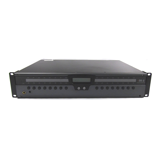
Introduction This publication provides technical information on servicing the Allen & Heath iDR-8 digital mix processor. Included are system block diagram, internal layout drawing and circuit schematics with board layouts. Whilst we believe this information to be reliable we do not assume responsibility for inaccuracies. - Page 3 Operation: The iDR-8 forms the heart of an iDR system. To test and configure the unit it should be connected to a PC running the Allen & Heath iDR System Manager software. It may be necessary to connect other parts of the system to the unit to fully test its function.
- Page 4 Contents Log Internal Layout drawing ............idr-8_layout_1.pdf Surface and Main Parts............idr-8_parts_2.pdf System Block Diagram ........idr-8_blockdiagram_1.pdf Analog Input PCB Assembly ....idr-8_003-004_analoginput_1.pdf ..............idr-8_003-004_analoginput_3.pdf ..............idr-8_003-004_analoginput_4.pdf Analog Output PCB Assembly....idr-8_003-005_analogoutput_2.pdf ..............idr-8_003-005_analogoutput_3.pdf ..............idr-8_003-005_analogoutput_4.pdf CPU PCB Assembly..........idr-8_003-006_cpu_1.pdf CPU PCB Assembly..........idr-8_003-006_cpu_2.pdf Comms1 PCB Assembly ......
- Page 5 – Historical Change Log The following list identifies historical changes to the iDR-8. The effective dates, serial numbers and related change note documentation are included for reference to help identify the correct issue circuit boards and components. Whilst we believe this information to be reliable we do not assume responsibility for inaccuracies.
Need help?
Do you have a question about the iDR-8 and is the answer not in the manual?
Questions and answers