ALLEN & HEATH iDR-4 User Manual
Digital audio mix processor
Hide thumbs
Also See for iDR-4:
- Manual (49 pages) ,
- Service information (5 pages) ,
- Service information (4 pages)

Related Manuals for ALLEN & HEATH iDR-4


Summary of Contents for ALLEN & HEATH iDR-4
- Page 1 Digital Audio Mix Processor USER GUIDE Hardware Configuration For software configuration refer to the iDR System Manager Help file Publication AP5230...
- Page 2 & Heath could void the compliance of the equipment and therefore the users authority to operate it. iDR-4 User Guide AP5230 Issue 2 Copyright © 2008 Allen & Heath Limited. All rights reserved Whilst we believe the information in this guide to be reliable we do not assume responsibility for inaccuracies.
-
Page 3: Important Safety Instructions
The wire which is coloured Blue or White must be connected to the terminal in the plug which is marked with the letter N. The wire which is coloured Brown or Black must be connected to the terminal in the plug which is marked with the letter L. iDR-4 User Guide... - Page 4 Allen & Heath iDR System Manager software required to configure the unit. Warnings For your own safety and to prevent damage to equipment make sure you read and adhere to all warnings. Model Serial Number Place of Purchase Date of Purchase IDR-4 User Guide...
-
Page 5: Table Of Contents
Contents Important Safety Instructions .......... 3 Welcome to the iDR-4 ............. 6 Main Features..............7 Front Panel Overview ............8 Rear Panel Overview ............9 System Processing Overview ........10 Getting Started - Check the Contents......13 iDR System Manager Software ........13 Installing the iDR-4 ............ -
Page 6: Welcome To The Idr-4
Two main units are available, the 2U high 8 in 8 out iDR-8, and the 1U high 6 in 6 out iDR-4. This user guide describes the iDR-4. -
Page 7: Main Features
Main Features • iDR-4 main processing unit 1U, 2 mic/line in, 4 • 8 Front panel soft keys can be assigned by the installer as level, mute or patch recall with different line in, 6 line out audio mix processor with 16x16 channel matrix. -
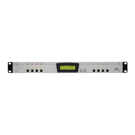
Page 8: Front Panel Overview
They can display red, green or yellow. unit. Soft keys 8 momentary action switches which can be assigned by the installer as level, mute or patch recall. IDR-4 User Guide... -
Page 9: Rear Panel Overview
PC operation. The cable. Two cables are required between the ‘link’ lights when communication expander and iDR-4, one for the audio, the other established. The ‘TX’ LED lights when data is for DR-Link control. communicated. Audio inputs Balanced XLR inputs for... -
Page 10: System Processing Overview
5 and 6. iDR-4 and iDR-8 units can be daisy chained together using the 8 channel wide digital expander bus to create even more flexible systems with additional local inputs and outputs and a maximum 16x16 matrix. - Page 11 16x16 matrix. patchbay. Variable frequency sine wave, pink Analogue inputs The iDR-4 has 2 analogue XLR noise, white noise or 1/3 octave band pass noise inputs feeding high grade balanced mic/line can be selected. These can be used for system line up and testing.
- Page 12 With no monitor point selected, the signal from the previous iDR unit is passed through to the output. This means that one monitor output can be used to listen to any point in a multiple iDR system. IDR-4 User Guide...
-
Page 13: Getting Started - Check The Contents
< > AUDIO MIX PROCESSOR ENTER 1x iDR-4 UNIT. This is packed with its face plate removed and iDR-4 AUDIO MIX PROCESSOR rack ears fitted. The ears can be removed for desk mounting. 1x iDR-4 FACE PLATE. Separately packed so that you can start by configuring the unit using its front panel menu system. -
Page 14: Installing The Idr-4
Installing the iDR-4 The iDR-4 and its expanders are supplied ready Do not obstruct the side ventilation slots. for 19” rack mounting. For desk top or shelf Ensure adequate air flow around the units. mounting remove the rack ears and fit the 4 press- in rubber feet provided. -
Page 15: Earthing
This is a requirement when an alarm or voice evacuation system is integrated. Check which safety standards apply to your installation. A backup UPS supply may be required. The standards may also apply to the grade of cable and installation methods required. iDR-4 User Guide... -
Page 16: Starting Offline With The Software
& Heath menu. To open a new session click on the blue icon, press Ctrl+N, or open the New item in the File menu. Select “Offline iDR-4” to start an offline session to get familiar with the program before you connect the iDR-4 unit. -
Page 17: Checking The Operating Code Version
RS232 SYSNET (code) plate. Select CODE UPDATE by sliding the recessed switch in the direction of the arrow. Turn the iDR-4 on by pressing the active active rear panel ON/OFF switch. The LCD displays the boot code version number and ‘Update...’. -
Page 18: The Idr-4 Setup Menus
REMOVE THESE SCREWS iDR-4 AUDIO MIX PROCESSOR The iDR-4 Setup Menus PRESS AND HOLD FOR 2 SECONDS *1 Patch Select Scroll through the available patches and recall the one you want. This can be useful for recalling test patches for system checking without the need for connecting to a PC. -
Page 19: Setting The Unit Name
ENTER Before your PC can take control of the iDR-4 you need to set up its unit name and communication settings. This is done using a simple front panel menu system. Once communication is established between the PC and iDR-4 you use the iDR System Manager software to configure the DSP resources and parameters. -
Page 20: Getting Started - Checking The Hardware
Getting Started – Checking the Hardware The iDR-4 is supplied with its settings pre-configured so that you can turn it on and immediately get audio passing through it. This can be useful when you are installing a unit on site and need to carry out initial tests on the hardware before the custom configuration software is loaded. -
Page 21: Communicating With The Idr
Windows™ iDR System Manager application. The application can be password protected to prevent unauthorised access. You need to connect your PC to the iDR-4. To get them to communicate you must first access the front panel Setup menus and set up a few communications settings. You also need to set up your PC to work with these settings. -
Page 22: Communicating Using Tcp/Ip
It is also possible that the PC you use to configure iDR-4 the iDR-4 is also used with a network at your place of work. If it AUDIO MIX PROCESSOR is served by a DHCP server then it is likely that it does not have its own permanent IP address as this is leased by the server. -
Page 23: Connecting Direct To A Pc
DHCP should be turned off (see below). If an address change is needed, consider whether you want to change it on the iDR-4 unit or your PC. To make this decision you may need to consult with the network administrator if the unit or the PC is also used with a network, or the site engineer if other PCs are to be used with the unit. -
Page 24: Communicating Using A Dial-Up Connection
A and B available. To use RS232 make sure one of the top two is selected. Reboot the iDR-4 for the changes to take effect. Setting up a Dial-up Connection You can simply use the factory default PPP settings. -
Page 25: Connecting To A Modem Using Rs232
Programs / Allen & Heath / iDR System Manager Vnnn. Click on the blue icon or File menu New item. Type the Host IP Address into the window. This is as set in the iDR-4 Setup menu *6.1 PPP settings. Click OK. Note that the program will run a lot slower than direct network connection. -
Page 26: Working With Idr System Manager
Sync to PC button to load in the current PC time and day settings. Archiving and Loading Configurations The way the iDR-4 is set up and the contents of any patches which have been created is stored as a ‘configuration’. It can be archived as a .cfg file on your PC. -
Page 27: Xlr Analogue Inputs And Outputs
The Output Select window Click on the XLR within the Output Select window to open up its Analog Output window. Check that the source channel number displayed is the one you want to send to the output XLR. iDR-4 User Guide... -
Page 28: Trs Jack Inputs And Outputs
System Manager software to become the stereo monitor L and R line level outputs. Configuring the Stereo Monitor The factory default configures the iDR-4 as a 6 in, 6 out system without monitor. This is regarded as the most typical application. - Page 29 *7 Monitoring 3. Soft key assignment Any soft key such as those on the iDR-4 front panel, the iDR-switch or PL wall plates can be assigned as a monitor select for an input or output channel. Refer to the Help file that comes with the iDR System Manager software.
-
Page 30: Adding Idr-In And Idr-Out Audio Expanders
Complies with UL6500, CSA-E65, EN60065 iDR-in and iDR-out are add-on audio expander units for the iDR-4 and iDR-8 audio mix processors. They provide additional analogue audio inputs and outputs to add to those on the main unit. The iDR-in has 8 mic/line inputs, the iDR-out has 8 line outputs. - Page 31 Fully expanded iDR-4 This diagram shows the iDR-4 DR-LINK iDR-in with both the input and output expander fitted. Note the connection of DR-Link which is daisy chained from one unit to the next. If an iDR-switch unit is also fitted then daisy chain DR-LINK DR-Link from the last expander to the switch box.
-
Page 32: Linking Idr-4 Units
Linking iDR Units Several iDR-4 and iDR-8 units can be daisy chained together such that audio is passed between them using the 8 channel expander bus. An iDR-in expander can be added to the first unit in the chain, and an iDR-out expander can be added to the last unit. - Page 33 Loop back system This example shows two iDR-4 units connected with the audio bus looped back from the last to the first. This means that all inputs are available to both units iDR-4 - A using the patchbays and matrix. Note that each unit must have...
-
Page 34: Adding The Idr-Switch Expander
Complies with UL6500, CSA-E65, EN60065 The iDR-switch is an add-on control expander for the iDR-4 and iDR-8 audio mix processors. It provides an additional 24 switch closure control inputs and 16 logic control outputs in a 1U high rack or desk mount case. Up to three units can be connected providing up to 72 additional switch and 48 additional logic controls. - Page 35 Do not use the chassis ground screw which is for cable shielding and safety earthing only. INTERNAL DR-switch CIRCUIT (1 OF 8 SHOWN) For reliable operation we recommend the use of heavy duty OPTO sealed switches. iDR-4 User Guide...
- Page 36 3-colour LEDs which can be hard wired to the unit. It can be fitted into a UK or US standard single wall box. For further details visit the Allen & Heath web site. iDR-switch link power iDR-switch 24 IN 16 OUT SWITCH CONTROLLER Switch closures Open-collector logic Relays Lamps IDR-4 User Guide...
-
Page 37: Sysnet And Pl-Anet Ports
Together with RS232, the SysNet and PL-Anet serial ports are part of the communications options available. The iDR-4 offers huge flexibility by offering these popular ports. However, they are not all available at the same time. The iDR allocates two ports A and B. You need to select two of the three options using the iDR System Manager software Communications Option window. -
Page 38: The Idr-4 Memory System
The iDR-4 Memory System The iDR-4 has onboard flash memory. This is non-volatile memory that retains its settings when power is removed. Although the unit is configured using a PC, it holds its own operating code and settings in this memory for stand alone operation once the PC is removed. -
Page 39: Starting With Patches
The patch system is the key to the iDR system’s unique flexibility. Unlike some systems which simply take a ‘snapshot’ of all the current settings, the iDR-4 can store and recall any number of chosen settings from an extensive list of parameters. -
Page 40: Technical Specification
FOR CONTINUED PROTECTION AGAINST RISK OF FIRE REPLACE FUSE WITH SAME TYPE AND RATING. CAUTION: RISK OF ELECTRIC SHOCK. DO NOT OPEN. AVIS: RISQUE DE CHOC ELECTRIQUE - NE PAS OUVRIR. Made in the UK by ALLEN&HEATH LIMITED Complies with UL6500, CSA-E65, EN60065 IDR-4 User Guide... - Page 41 XOVER FILTER EXPANDER INPUT PAGER SILENCE FADER MONO SIG GEN SIDECHAIN SOURCE OSCILLATOR FILTER FREQ PINK NOISE WHITE NOISE 1/3 OCT BP ANALOG DUCKING OUTPUT MUTE STEREO FADER RELAY RIPPLE THROUGH SELECT 15+16 ACTIVE MONITOR BUS MUTE iDR-4 User Guide...
- Page 42 Description Mic/Line Inputs x2 (x10 expanded) iDR-4 2 mic / 4 line in, 6 line out main processor Female 3pin XLR iDR-8 8 mic/line in, 8 line out main processor Electronically balanced, pin 2 hot iDR-in 8 mic/line in audio expander Impedance 2k ohm (pad out), >10k ohm (pad in)
-
Page 43: Power Supply
9pin D female, RS232 AC mains input 100-240V AC 50/60Hz Baud rate 19200, 8N1 Variable speed cooling fan in iDR-4 Cable length <3 metres (10 feet) iDR-4 75VA max, T1.6AL 20mm fuse Refer to Allen & Heath iDR SysNet protocol... - Page 44 LCD Display Downloadable from Allen & Heath web site 2x16 character, grey, backlit iDR-4 operating code – can be updated via RS232 Assignable display, patch related using Windows™ HyperTerminal, or via network using Combinations of clock, unit name and user text...
-
Page 45: Fader Groups
Indicators – any soft LED Notch filter width 10Hz to 100Hz Ducker depth 0 to -40dB Crossover filter Butterworth / Linkwitz-Riley up to Controls – page mic select, zone select 24dB/octave Display - frequency response curve, meter Controls – in/out, flatten iDR-4 User Guide... -
Page 46: Factory Default Settings
L9-L12 – input source meters CH1-4 L13-L16 – output post limiter meters CH1-4 iDR-switch outputs S1-S16 – static LED off Input expander S1-S8 – input source meters CH9-16 Output expander S1-S8 – Output post limiter meters CH9-16 IDR-4 User Guide... -
Page 47: Template For Front Panel Label
Edit the text to identify the key and LED functions (maximum of three lines per cell, each with eight characters). Overall size of each label is 178.5 x 12.5 mm. Adhere the labels into the iDR-4 front face plate slots provided. iDR-4 User Guide... - Page 48 IDR-4 User Guide...
Need help?
Do you have a question about the iDR-4 and is the answer not in the manual?
Questions and answers