
Related Manuals for Noyes AFL OPM5-2D


Summary of Contents for Noyes AFL OPM5-2D
- Page 1 Noyes OLS 1 OLS 2 OPM 5 Specs Provided by www.AAATesters.com OLS Series Light Sources, OPM Series Optical Power Meters, and Related Test Kits User’s Guide www.AFLglobal.com/go/NOYES or 1-800-321-5298/1-603-528-7780...
- Page 2 Warranty All NOYES test equipment products are warranted for a period of (1) one year from the date of delivery to the end user. Extended warranties start at the end of the standard (1) one year warranty period. 1 year, 2 year, and 4 year extended warranties are available for NOYES products with or without annual calibration included.
-
Page 3: Table Of Contents
Table of Contents Safety Information .................4 General Information ................5 OPM-Series Optical Power Meters ............6 OPM4 Models ................6 Ports and Display ..............6 Dual Function Keys ...............7 Test Mode: To Set Reference ..........8 Test Mode: To View Reference ..........8 Display Readings - Splash and Auto Off Screen .....8 Display Readings in Test Mode ..........9 OPM5 Models ................10 New Feature ................10... -
Page 4: Safety Information
- Do NOT insert a 9V battery into unit. It is designed to operate from 2xAA batteries only NOTICE! NOYES power meters and light sources contain no user serviceable parts. Except for changing batteries and cleaning optical ports, these units must be returned to NOYES or authorized agents for repair and calibration. -
Page 5: General Information
An OPM optical port must be equipped with an adapter cap. A variety of adapter caps, connector adapters, and test jumpers with a variety of lengths and connector styles are available from AFL - NOYES. Optical ports and connector end faces must be kept free from dirt or other contaminates to ensure accurate measurements and operation. -
Page 6: Opm-Series Optical Power Meters
Ports and Display REF # DESCRIPTION Optical input (adapter cap mount) - accepts NOYES thread-on adapter caps. Adapter cap - the OPM4 optical input must be equipped with an adapter cap. Display - depending on the selected mode, shows measured power dBm or µW or insertion loss dB, calibrated wavelengths, tone signal Hz, wavelength ID, references, and battery charge status. -
Page 7: Dual Function Keys
OPM4 Models Dual Function Keys Press and hold to activate Secondary function of a key Primary function of a key Press and release to activate Power key Provides two functions: • Press the key to turn the OPM4 on/off. The unit will turn off automatically five minutes after the last key press. -
Page 8: Test Mode: To Set Reference
OPM4 Models Ref/Set key Provides two functions: • To set Reference • To display Reference Test Mode: To Set Reference 1. Set your OPM4 to the desired measurement mode (dB, dBm, µW). 2. To store the currently measured level or multiple levels as the new reference levels, press and hold the Ref key until the label HELD SET is displayed. -
Page 9: Display Readings In Test Mode
OPM4 Models Display Readings in Test Mode 8888 8888 -88.88 -88.88 µW µW dB dBm dB dBm 8888 8888 WAVE ID WAVE ID -88.88 µW dB dBm Single WAVE mode, or Dual WAVE mode, or Tri WAVE mode - second page Tri WAVE mode - first page REF. -
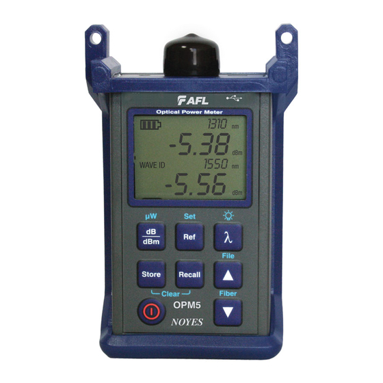
Page 10: Opm5 Models
Ports and Display REF # DESCRIPTION Optical input (adapter cap mount) - accepts NOYES thread-on adapter caps. Adapter cap - the OPM5 optical input must be equipped with an adapter cap. Mini-USB type B port: - allows connection to a PC for downloading stored test results - interface for AC power adapter Display - depending on the selected mode, shows measured power dBm or µW or insertion loss... -
Page 11: Dual Function Keys
OPM5 Models Dual Function Keys Press and hold to activate Secondary function of a key Primary function of a key Press and release to activate Power key Provides two functions: • Press the key to turn the OPM5 on/off. The unit will turn off automatically five minutes after the last key press. -
Page 12: Display Readings - Splash And Auto Off Screen
OPM5 Models dB/dBm/µW key Provides two functions: • Press to toggle test readings between insertion loss in dB and power in dBm A . • Press and hold to view power in µW B . 8888 -88.88 µW dB dBm 8888 WAVE ID -88.88... -
Page 13: Display Readings In Test Mode
OPM5 Models Display Readings in Test Mode 8888 8888 -88.88 -88.88 µW µW dB dBm dB dBm 8888 8888 WAVE ID WAVE ID -88.88 µW dB dBm Single WAVE mode, or Dual WAVE mode, or Tri WAVE mode - second page Tri WAVE mode - first page REF. -
Page 14: File Manager: To Select Current File
OPM5 Models File Manager: To Select Current File 1. Press and hold the Arrow/File key to enter the File Manager - File mode screen. 2. A blinking cursor A to the left of FILE indicates that you are in the File mode. FILE FibS B - File indicator... -
Page 15: Test Mode: To View Reference
PC for analyzing, generating professional test reports, and printing. For more information, refer to the TRM software User’s Guide (available on the supplied CD and from the AFL - NOYES web at www.AFLglobal.com/go/Software). 1. Set your OPM5 to the desired measurement mode (dB, dBm, µW) and wavelengths. -
Page 16: Recall Mode: To View Stored Records
OPM5 Models 5. The current measurements are stored in the next available memory location (next Fiber) of the current File. Recall Mode: To View Stored Records 1. Press and hold the Arrow/File key to enter File mode and select the desired File to view. 2. -
Page 17: To Edit Stored Records
OPM5 Models To Edit Stored Records 1. If needed, press and hold the Arrow/File key to enter File mode and select the desired File. Press the Store key to exit the File mode. 2. Press and hold the arrow key to enter the Fiber mode and select the fiber to edit. •... -
Page 18: Ols-Series Light Sources
850/1300/CW 1300nm wavelengths key Power key Low Battery NOYES indicator OLS1-Dual Features 1. Output port - Universal Connector Interface (UCI). Accepts swappable SC connector (ST, FC, and LC connector styles are available). 2. Active Output indicators (illuminated when the corresponding output port is ON) - The Active... - Page 19 OLS1-Dual LED Light Source Dual 850/ 1300 nm 850 nm 1300 nm Dual 850/ 1300 nm • Press and hold the key to switch to the CW mode at the currently selected wavelength. Note: If the OLS1 operates in the Dual WAVE ID mode, it will switch the output port to the next wavelength in a sequence as follows: Dual 850/1300 nm WAVE ID key Press and hold...
- Page 20 Output Adjust keys Adjust Power key Low Battery NOYES indicator OLS2-Dual features 1. Power key - Press and hold the key until all indicators light up to turn the OLS2-Dual On or Off. The instrument turns on in its last operating condition it was in prior to being turned off.
- Page 21 OLS2-Dual Laser Source WAVE ID Mode (WAVE ID indicator on) Press the l key to select wavelengths in the following sequence: • Dual 1310/ 1550 nm 1310 nm 1550 nm Dual 1310/ 1550 nm Note: When a wavelength is selected, the corresponding Active Output indicator on the front panel is illuminated.
- Page 22 “step size counter” to zero. Note: End of adjust range indication - NOYES recommends using an Optical Power Meter to monitor the output when adjusting the OLS2-Dual power level. However, this is not necessary to set the OLS2-Dual to the maximum or minimum output level.
-
Page 23: Ols4 Integrated Led And Laser Light Source
Tone Power key Low Battery indicator NOYES OLS4 Features 1. Power key - Press and hold the key until all indicators light up to turn the OLS4 ON or OFF. The OLS4 turns on in its default condition: 850/1300 nm Dual mode sending Wavelength ID. - Page 24 OLS4 Integrated LED and Laser Light Source 7. Active Output indicators (illuminated when the corresponding output port is ON) - The Active Output indicators light up as follows: Test Mode Active Output indicator status WAVE ID dual Wave corresponding indicators - ON continuous light WAVE ID single Wave corresponding indicator - ON continuous light CW or Tone corresponding indicator - ON blinking light...
-
Page 25: Ols7-3 Triple Wavelength Laser Source
Mode Mode key Wavelengths Power key NOYES Low Battery indicator OLS7-3 Features 1. Power key - Press this key to turn the OLS7-3 on or off. When the unit is turned on, it returns to the last operating condition it was in prior to being turned off. - Page 26 OLS7-3 Triple Wavelength Laser Source Triple 1310/ 1550/ 1625 nm 1310 nm 1550 nm 1625 nm Dual 1310/ 1550 nm Dual 1550/ 1625 nm Triple 1310/ 1550/ 1625 nm Note: When a wavelength is selected, the corresponding Active Output indicator on the front panel is illuminated.
-
Page 27: Ols7-Ftth Triple Wavelength Laser Source
Mode Mode key Wavelengths Power key NOYES Low Battery indicator OLS7-FTTH Features 1. Power key - Press this key to turn the OLS7-FTTH on or off. When the unit is turned on, it returns to the last operating condition it was in prior to being turned off. - Page 28 OLS7-FTTH Triple Wavelength Laser Source WAVE ID Mode (WAVE ID indicator on) Press the l key to select wavelengths in the following sequence: • Dual 1490/ 1550 nm 1310 nm Triple 1310/1490 / 1550 nm Note: When a wavelength is selected the corresponding Active Output indicator on the front panel is illuminated.
-
Page 29: Measuring Optical Power
7. OPM5 power meters only: You may press the Store key to save the displayed measurement in the next available memory location. fiber optic equipment Output Input adapter cap OPTICAL POWER METER test jumper 0000 0.00 µW 0000 WAVE ID 0.00 µW µW Store Recall Clear OPM 5 NOYES... -
Page 30: Testing Multimode Links
Testing Multimode Links Step I - Set the Reference (One Jumper Method) 1. Turn on the OPM optical power meter and OLS optical light source. Allow the light source to stabilize (minimum of 2 minutes). 2. If not using the WAVE ID feature, set both instruments to the desired test wavelength. 3. - Page 31 13. Mate the free ends of the transmit and receive jumpers using the appropriate adapter. 14. Verify that the insertion loss of this mated connector pair is under 0.75 dB, the maximum allowed by the TIA (NOYES recommends 0.4 - 0.5 dB typical), as follows: •...
- Page 32 Testing Multimode Links Step III - Measure Multimode Link Insertion Loss 17. Connect the free ends of the transmit and receive jumpers to the multimode link under test. Clean jumper end that connects to patch panel prior to every test! 18.
-
Page 33: Testing Single-Mode Links
Testing Single-mode Links Step I - Set the Reference (One Jumper Method) 1. Turn on the OPM optical power meter and OLS optical light source. Allow the light source to stabilize (minimum of 2 minutes). 2. If not using the WAVE ID feature, set both instruments to the desired test wavelength. 3. - Page 34 13. Mate the free ends of the transmit and receive jumpers using the appropriate adapter. 14. Verify that the insertion loss of this mated connector pair is under 0.75 dB, the maximum allowed by the TIA (NOYES recommends 0.4 - 0.5 dB typical), as follows: •...
- Page 35 Testing Single-mode Links Step III - Measure Single-mode Link Insertion Loss 17. Connect the free ends of the transmit and receive jumpers to the single-mode link under test. Clean jumper end that connects to patch panel prior to every test! 18.
-
Page 36: Maintenance Tips
Maintenance Tips Cleaning Optical Ports CAUTION! Before conducting the following procedures be sure to have the instruments turned OFF. Optical ports must be kept free from dirt or other contaminants to ensure accurate measurements and operation. Always clean all test jumpers before conducting the test procedures outlined in this Guide. It is important to keep dust caps in place when instruments are not being used. -
Page 37: Repair And Calibration
Repair of the NOYES test equipment in the field is NOT recommended. Calibration is recommended every 12 months. NOYES Calibration Department is in compliance with ANSI/ NCSL Z540-1, ISO 10012-1, MIL STD 45662A, ISO Guide 25 and traceability to the National Institute of Standards and Technology. - Page 38 Thank you for choosing NOYES Test and Inspection 9001 www.AFLglobal.com/go/NOYES www.AFLglobal.com/go/NOYES or 1-800-321-5298/1-603-528-7780...