Sign In
Upload
Download
Table of Contents
Contents
Add to my manuals
Delete from my manuals
Share
URL of this page:
HTML Link:
Bookmark this page
Add
Manual will be automatically added to "My Manuals"
Print this page
×
Bookmark added
×
Added to my manuals
Manuals
Brands
Noyes Manuals
Measuring Instruments
M series
User manual
Noyes M series User Manual
Otdrs
Hide thumbs
1
2
Table Of Contents
3
4
5
6
7
8
9
10
11
12
13
14
15
16
17
18
19
20
21
22
23
24
25
26
27
28
29
30
31
32
33
34
35
36
37
38
39
40
41
42
page
of
42
Go
/
42
Contents
Table of Contents
Bookmarks
Table of Contents
Table of Contents
Safety Information
Getting Started: Front Panel Keys
M700 Menus Tip
Main Menu: Selecting the Mode
Getting Started: Display Features
Setup: General Settings
Setup: Full Auto Mode Settings
Setup: Expert Mode Settings
Setup: Real-Time Mode Settings
Setup: Event Settings
Event Settings: Pass/Fail
Setup: OPM Mode Settings
Setup: New Job Creation
Setup: Results Manager
Job Creation in Results Manager
Job Selection from a Test Mode
Opening a Trace File for Review
Saving Test Results
Running Tests & Viewing Results
Trace Page Features
Event Table & Summary Results
Fault Locating: Full Auto
Two Point A/B Measurement
Text Editor
Numerical Editor
Transferring Files
Recommended Accessories
Specifications
Cleaning Tips
Faqs
Tips: Expert OTDR Setup
Recharging Batteries
Repair and Calibration
View Version Information
Contact Us
Advertisement
Quick Links
1
Table of Contents
2
Getting Started: Front Panel Keys
3
M700 Menus Tip
4
Running Tests & Viewing Results
Download this manual
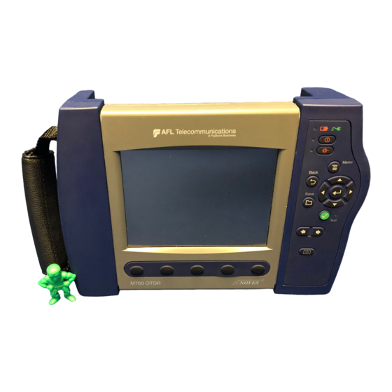
M-Series OTDRs
User's Guide
Table of
Contents
Previous
Page
Next
Page
1
2
3
4
5
Advertisement
Table of Contents
Need help?
Do you have a question about the M series and is the answer not in the manual?
Ask a question
Questions and answers
Related Manuals for Noyes M series
Measuring Instruments Noyes M700 User Manual
Otdrs (42 pages)
Measuring Instruments Noyes OPM4 User Manual
Ols series light sources, opm series optical power meters, and related test kits (38 pages)
Measuring Instruments Noyes OFL-200 User Manual
Single-mode optical time domain reflectometer (57 pages)
Measuring Instruments Noyes OLS Series User Manual
Light sources, optical power meters, and related test kits (38 pages)
Measuring Instruments Noyes AFL OPM5-2D User Manual
Light sources, optical power meters, and related test kits (38 pages)
Measuring Instruments Noyes AFL OPM Series User Manual
Light sources, optical power meters, and related test kits (38 pages)
Measuring Instruments Noyes OPM Series User Manual
(40 pages)
This manual is also suitable for:
M700
Table of Contents
Print
Rename the bookmark
Delete bookmark?
Delete from my manuals?
Login
Sign In
OR
Sign in with Facebook
Sign in with Google
Upload manual
Upload from disk
Upload from URL


Need help?
Do you have a question about the M series and is the answer not in the manual?
Questions and answers