Table of Contents
Advertisement
Quick Links
Advertisement
Table of Contents

Related Manuals for Hioki 3273


Summary of Contents for Hioki 3273
- Page 1 INSTRUCTION MANUAL 3273 CLAMP ON PROBE...
-
Page 3: Table Of Contents
Contents Introduction Inspection Safety Notes Note on Use Chapter 1 Overview 1.1 Product Overview 1.2 Features 1.3 Names of Parts 1.4 Parts of the Sensor Chapter 2 Specifications 2.1 Product Specifications 2.2 Standards Applying Chapter 3 Measurement Procedure 3.1 Notes on Use 3.2 Preparations for Measurement 3.3 Demagnetizing and Zero Adjustment 3.4 Measurement Procedure... -
Page 5: Safety Notes I
____________________________________________________ Introduction Thank you for purchasing the HIOKI "3273 CLAMP ON PROBE". To obtain maximum performance from the device, please read this manual first, and keep it handy for future reference. Inspection When you receive the device, inspect it carefully to ensure that no damage occurred during shipping. - Page 6 ____________________________________________________ Safety Symbols This manual contains information and warnings essential for safe operation of the device and for maintaining it in safe operating condition. Before using the device, be sure to carefully read the following safety notes. symbol printed on the device indicates that the user should refer to a corresponding topic in the manual (marked with the...
- Page 7 ____________________________________________________ Overvoltage Categories (CAT) This device conforms to the safety requirements for CAT I measurement instruments. To ensure safe operation of measurement instruments, IEC 60664 establishes safety standards for various electrical environments, categorized as CAT I to CAT IV, and called overvoltage categories.
-
Page 8: Note On Use
DANGER To avoid short circuits and potentially life- threatening hazards, follow these precautions. Never attach the 3273 to a circuit that operates at more than 300V, or over bare conductors. While the core section is open, and when conductors being measured carry in excess of... - Page 9 ____________________________________________________ DANGER This device is made for use with the 3272 POWER SUPPLY. It is possible to use a power supply other than the 3272, provided that the connector and pin assignments match, and that voltage and other electrical specifications are satisfied.
- Page 10 ____________________________________________________ DANGER 2. If basic insulation requirements cannot be met between the terminal to which this device is connected and other terminals of the measuring instrument, make sure that the voltage input to the measurement terminal does not exceed the safe voltage level (SELV- 3.
- Page 11 ____________________________________________________ DANGER Be sure to observe all operating precautions for the waveform monitoring instrument (oscilloscope or recorder) and other measurement instruments to which this device is connected When using a measurement instrument that does not provide isolation between its input terminals and chassis or other input terminals, please pay attention to the following points.
- Page 12 Before using the device the first time, verify that it operates normally to ensure that the no damage occurred during storage or shipping. If you find any damage, contact your dealer or Hioki representative. This device is not designed to be entirely water- or dust-proof.
- Page 13 ____________________________________________________ CAUTION The matching surfaces of the sensor head are precision ground, and should be treated with care. If these surfaces are scratched, performance may be impaired. Measurements are degraded by dirt on the mating surfaces of the sensor head, so keep the surfaces clean by gently wiping with a soft cloth.
- Page 14 Hioki representative. When sending the device for repair, pack carefully to prevent damage in transit. Include cushioning material so the 3273 cannot move within the package. Be sure to include details of the problem. Hioki cannot be responsible for damage that occurs during shipment.
-
Page 15: Chapter 1 Overview
Highly accurate current detection Easy current measurement Broadband frequency characteristics DC to 50 Compact and permits measurement of low current levels Easy protect function at excessive input Unique HIOKI development of thin film Hall effect element _______________________________________________ Chapter 1 Overview... -
Page 16: Names Of Parts
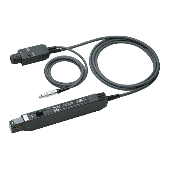
____________________________________________________ 1.3 Names of Parts External view Current direction indication Sensor Terminator "UNLOCK" indication Power supply cable Sensor cable _______________________________________________ Chapter 1 Overview... -
Page 17: Parts Of The Sensor
____________________________________________________ 1.4 Parts of the Sensor 1. Opening lever Operating lever for opening the sensor head. Always use this lever to open the sensor head. 2. Sensor head This clamps the conductor being measured, and carries out the actual current measurement. It is a precision assembly including a molded component, a ferrite core, and a Hall effect element. - Page 18 ____________________________________________________ 6. Output connector The current waveform of the measured conductor is output at a constant rate (0.1 V/A). Connect to the BNC input connector of the waveform measuring instrument. The output of this device is terminated internally. NOTE Use a high-impedance input to the measuring instrument.
-
Page 19: Chapter 2 Specifications
____________________________________________________ Chapter 2 Specifications 2.1 Product Specifications Guaranteed at 23 (73 ±9 ) after the ±5 power has been on for 30 minutes. Frequency DC to 50 MHz (-3 dB) (Characteristics range shown in Fig. 1) Rise time 7 ns or less Maximum 15 A continuous input... - Page 20 ____________________________________________________ Maximum rated 3 VA power Rated supply 12 V voltage Operating 0 to 40 (32 to 104 ), 80 %RH or temperature and less (no condensation) humidity range Storage 10 to 50 (14 to 122 ), 80 %RH or temperature and less (no condensation) humidity range...
-
Page 21: Standards Applying
____________________________________________________ Mass Approx. 230 g Approx. 8.1 oz. Accessories Instruction manual, soft case 2.2 Standards Applying Safety EN61010-2-032:1995 Overvoltage category I (anticipated transient overvoltage 1500 V), Pollution Degree 2 EN61326:1997+A1:1998+A2:2001 Frequency [Hz] Figure1 Frequency characteristics _______________________________________________ Chapter 2 Specifications... - Page 22 ____________________________________________________ Frequency [Hz] Figure2 Derating according to frequency Frequency [Hz] Figure3 Input impedance (Characteristics) _______________________________________________ Chapter 2 Specifications...
-
Page 23: Chapter 3 Measurement Procedure
DANGER To avoid short circuits and potentially life- threatening hazards, follow these precautions. Never attach the 3273 to a circuit that operates at more than 300V, or over bare conductors. While the core section is open, and when conductors being measured carry in excess of... - Page 24 ____________________________________________________ DANGER This device is made for use with the 3272 POWER SUPPLY. It is possible to use a power supply other than the 3272, provided that the connector and pin assignments match, and that voltage and other electrical specifications are satisfied.
- Page 25 ____________________________________________________ DANGER 2. If basic insulation requirements cannot be met between the terminal to which this device is connected and other terminals of the measuring instrument, make sure that the voltage input to the measurement terminal does not exceed the safe voltage level (SELV- 3.
- Page 26 ____________________________________________________ DANGER Be sure to observe all operating precautions for the waveform monitoring instrument (oscilloscope or recorder) and other measurement instruments to which this device is connected When using a measurement instrument that does not provide isolation between its input terminals and chassis or other input terminals, please pay attention to the following points.
-
Page 27: Preparations For Measurement
3272. (2) Turn the power switch off and connect the power cord. (3) Connect the power plug of the 3273 to the power receptacle of the 3272. (4) Turn the 3272 power switch on, and check that the front panel power indicator lights. -
Page 28: Demagnetizing And Zero Adjustment
(2) Set the input coupling of the waveform measurement instrument to DC. (3) Connect the output connector of the 3273 to the input connector of the waveform measurement instrument. Turn the collar until it clicks, and check that it is locked securely. - Page 29 If using BNC-banana plug adapters or similar to connect to input terminals other than BNC connectors, make sure the polarity is correct. Do not demagnetize while the 3273 is clamping a conductor to be measured. Demagnetizing causes current to flow into the conductor, which may damage parts in the circuit to be measured.
-
Page 30: Measurement Procedure
____________________________________________________ (7) If zero adjustment is not possible in step 6, turn the coarse adjustment trimmer to bring the trace within the range of adjustment by the zero adjustment dial. 3.4 Measurement Procedure (1) Check that the system is safe, and that the preparations described in the preceding section have been carried out. - Page 31 ____________________________________________________ (5) It is now possible to monitor the current waveform. The output rate of the 3273 is 0.1 V/A. The current sensitivity can be derived from the voltage sensitivity of the waveform measurement instrument. For example, if the voltage sensitivity is 10 mV/division, the current sensitivity is 100 mA/division.
- Page 32 ____________________________________________________ WARNING The maximum continuous input range is based on heat that is internally generated during measurement. Never input current in excess of this level. Exceeding the rated level may result in damage to the probe. The maximum continuous input range varies according to the frequency of the current being measured.
- Page 33 ____________________________________________________ WARNING The probe is rated for maximum input under two conditions in addition to the input maximums shown in the "Product Specifications." These are (1) 30 Apeak, for non-continuous input, and (2) 50 Apeak for pulse widths 10µs. (1) indicates an upper waveform response limit of 30 Apeak.
- Page 34 ____________________________________________________ When performing continuous measurements, it is NOTE necessary to be aware that the offset voltage drifts, depending on factors such as the ambient temperature. Under certain circumstances, oscillation may occur if the probe is connected to the 3272 POWER SUPPLY while the power supply is on.
- Page 35 ____________________________________________________ Power Load source Accurate measurement may be impossible in NOTE locations subject to strong external magnetic fields, such as transformers and high-current conductors, or in locations subject to strong external electric fields, such as radio transmission equipment. _______________________________________________ Chapter 3 Measurement Procedure...
- Page 36 ____________________________________________________ _______________________________________________ Chapter 3 Measurement Procedure...
Need help?
Do you have a question about the 3273 and is the answer not in the manual?
Questions and answers