Advertisement
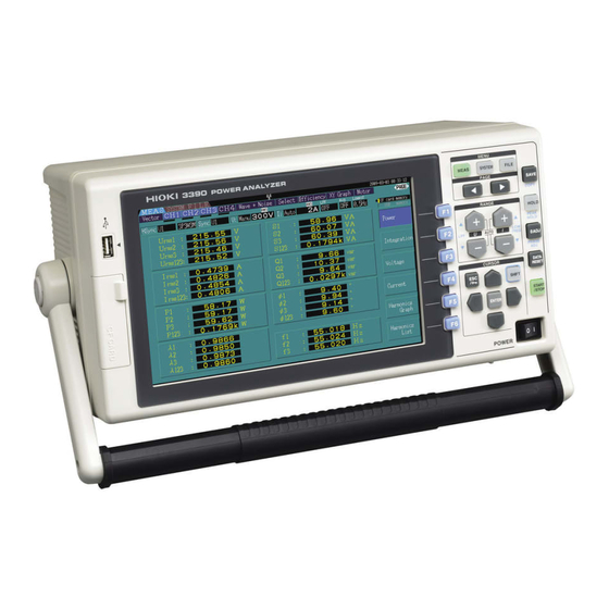
Always-Displayed Items
1
2
3
Displayed
Displayed
Operating State Indicators
Screen
Page
1
Displayed Screen
Measurement screen (Press
display)
System screen (Press
to display)
File Operations Screen (Press
display)
2
Displayed Page
Each page shows different screen contents: select
the appropriate page as needed. Select the page
with
.
3
Operating State Indicators
Lights during integration and recording.
Indicates integration is in progress.
Indicates integration is stopped.
Indicates Data Hold is active.
Indicates Peak Hold is active.
4
Key-Lock Indicator
Lights to indicate Key Lock is active (keys are
locked, after holding
for three seconds).
Hold
again for three seconds to unlock.
Additional Capabilities
Connect an external device
(such as a printer or thermometer).
See the instruction manual for details, including setting
procedures for measurement and display, convenience fea-
tures and more.
4
Key-Lock Indicator
6
7
Storage Media
Interface Indicators
Indicators
5
Real-Time Clock
Displays the current date and time.
to
(To set the clock: See Chapter 6 of the instruction
manual.)
6
Interface Indicators
to
Lights when the instrument is connected to a
computer by USB cable (and the computer is on).
Lights when the instrument is connected to a LAN.
Indicates a printer is connected to the RS-232
interface.
Indicates a thermometer is connected to the RS-
232 interface.
Red: Temperature data has not been acquired.
Blue: Temperature data has been acquired.
7
Storage Media Indicators
Level indicators for the CF card and USB drive indi-
cate storage space usage. These turn from yellow to
red when the media is 95% full.
• Save measurement data and setting
Connect a computer for exter-
configurations.
nal control and data transfer.
• Reload setting configurations.
-4-
3390 POWER ANALYZER
5
Real-Time
Clock
Thank you for purchasing the HIOKI "Model 3390 Power Analyzer."
This guide introduces the Power Analyzer's basic measurement procedure to first-time users.
Before using the instrument, be sure to read the Instruction Manual carefully.
1.
Connect the Cables and Sensors, and Power On
Pre-connection inspection
Voltage measurement cables
Does any cable insulation appear damaged, or
is bare metal exposed?
Current sensors
Is a clamp cracked or damaged?
Instrument
Is damage to the instrument evident?
If damage is found
Contact your dealer or Hioki representa-
tive if you find any damage.
Power-on confirmation
• Does the self-test (model and version)
display appear?
• When the self-test finishes, does the
[Wiring]
page of the Setting or Mea-
surement screen appear (according to
when the instrument was last turned
off)?
If the self-test display does not
appear, or if an error is displayed
The power cord may be damaged, or the
instrument may have internal damage.
Please contact your dealer or Hioki repre-
sentative.
Operation keys
PAGE key
Changes the screen page.
F keys (Function keys)
Select and change display contents and
settings.
RANGE key
• Change the voltage (U) and current (I) mea-
surement ranges.
• Pressing the + and - keys at the same time
activates auto-ranging.
ESC key
• Cancels the last change to a setting,
and returns it to its previous state.
• Hold for three seconds to toggle the
key lock.
Measurement Guide
May 2013 Revised edition 1 Printed in Japan
3390A983-01 13-05H
Power cord
1
2
3
4
Voltage
Current sensor
measurement
cables
cables
MENU keys
Select a screen.
MEAS
key: Measurement screen
SYSTEM
key: System screen
FILE
key: File operation screen
ENTER key
CURSOR key
START/STOP key
Accepts selections and changes
Move the cursors.
Starts and stops integration and saving operations.
to settings.
-1-
Read First
5
Power-on
For best precision, allow
at least 30 minutes
warm-up before execut-
ing zero adjustment and
measuring.
SAVE key
• Saves data to the storage media.
SAVE
SHIFT
• Press
after pressing the
key to cap-
ture a screen image to the specified storage media or
to print it out. (Screen capture)
HOLD key
Toggles the Hold and Peak Hold function.
0 ADJ key
Performs zero adjustment and current sensor degaussing.
DATA RESET key
Resets the integration values.
SHIFT key
Activates alternate key functions.
Advertisement
Table of Contents

Related Manuals for Hioki 3390


Summary of Contents for Hioki 3390
- Page 1 May 2013 Revised edition 1 Printed in Japan 3390A983-01 13-05H Thank you for purchasing the HIOKI "Model 3390 Power Analyzer." This guide introduces the Power Analyzer's basic measurement procedure to first-time users. Before using the instrument, be sure to read the Instruction Manual carefully.
- Page 2 When execute quick setup Select Efficiency Executing quick setup automatically config- ures the following settings to the Hioki-recom- mended values for the selected wiring mode (phase system): voltage and current ranges, sync source, lower measurement frequency limit, integration mode, harmonic sync source and rectification method.
Need help?
Do you have a question about the 3390 and is the answer not in the manual?
Questions and answers