
Related Manuals for Reflex Reflexomat Basic RS 90 / 1


Summary of Contents for Reflex Reflexomat Basic RS 90 / 1
- Page 1 20.09.2020 - Rev. A Reflexomat Basic Reflexomat RS 90 / 1 - mounted Reflexomat - external air Operating manual Original operating manual...
-
Page 2: Table Of Contents
6.3.2 Tank installation ..............6 12 Annex ................17 6.3.3 Connection to the facility system ......... 6 12.1 Reflex Customer Service ............... 17 6.3.4 Connection to an external compressed air line ....7 12.2 Conformity and standards..............17 6.3.5 Fitting the level sensor............8 12.3... -
Page 3: Notes On The Operating Manual
Reflex Winkelmann GmbH accepts no liability for any damage resulting from Personnel requirements failure to observe the information in this operating manual. In addition to the... -
Page 4: Description Of The Device
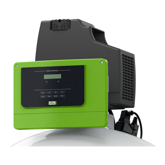
Meaning Control unit Type Device name The control unit comprises a "CO" compressor and the "Reflex Control Basic" controller. Via the primary vessel, the pressure is measured with the "PIS" Serial No. Serial number pressure sensor and the water level with the "LIS" pressure load cell and the min. -
Page 5: Scope Of Delivery
• For make-up with water – Make-up without pump: Note! • Solenoid "Fillvalve" with ball valve and Reflex Fillset for make- The following values apply for all vessels: up with drinking water. – Operating pressure: 6 bar – Make-up with pump: –... -
Page 6: Installation Conditions
Primary vessel with control unit prerequisite for the making of warranty claims. • Optional secondary vessel – Have the Reflex Customer Service carry out commissioning and the annual maintenance. Installation conditions 6.1.1 Incoming inspection Prior to shipping, this device was carefully inspected and packed. Damages during transport cannot be excluded. -
Page 7: Connection To An External Compressed Air Line
Damage due to improper installation the dimensions of the expansion lines, please see the planning Additional device stresses may arise due to the connection of pipes or system documents. More information is also provided in the Reflex Planning equipment. Guide. -
Page 8: Fitting The Level Sensor
Preferably, you should use the Reflex Fillset with integrated system separator when using drinking water for make-up. If you don't use a Reflex Fillset, you must use an "ST" dirt trap with a mesh size ≥ 0.25 mm for the make-up. -
Page 9: Electrical Connection
All entries in the fault memory. pressure. 6 M1 Note! If required, please contact the Reflex Customer Service for the protocol Overflow solenoid valve. of the RS-485 interface, details of the connections and information Factory • For controlling pressurisation about the accessories offered. -
Page 10: Installation And Commissioning Certificate
Note! prerequisite for the making of warranty claims. During commissioning, you must once execute the start routine. – Have the Reflex Customer Service carry out commissioning and • For information about controller operation, see chapter 9.1 the annual maintenance. "Operator panel" on page 12 . -
Page 11: Venting The Vessels
Operating modes controller" on page 12 . – Contact Reflex Customer Service, see 8.1.1 Automatic mode chapter 12.1 "Reflex Customer Service" on Use: page 17 . After initial commissioning has been successfully completed • No: The start routine restarts. –... -
Page 12: Stop Mode
If null • The Auto LED is not illuminated when the system is stopped balancing is still not possible, cancel with "Yes". Contact your Reflex Customer Service. • Confirm actions • NO: Check the prerequisites for the commissioning, Stop see chapter 7.1 "Checking the requirements for... -
Page 13: Default Settings
"Max. make-up volume exceeded". contact the Reflex Customer Service. With softening This value is only displayed if "YES" has been set in the "With water meter" menu option. -
Page 14: Messages
"P " minimum operating Alarm causes can be eliminated by the operator or a specialist workshop. If this is pressure. not possible, contact the Reflex Customer Service. "Compressor run time 240 minutes The message is displayed after exceeded" message the compressor runs for 240 ... -
Page 15: Maintenance
Note! DANGER Arrange for maintenance tasks must be carried out only by specialist personnel or Reflex Customer Service. Risk of serious injury or death due to electric shock. If live parts are touched, there is risk of life-threatening injuries. •... -
Page 16: Maintenance Schedule
Maintenance 10.1 Maintenance schedule Check make-up "Off" 15. If necessary, check the make-up value displayed at the controller. The maintenance schedule is a summary of maintenance tasks to be carried out – The automatic make-up is deactivated at a level display of 12 %. regularly. -
Page 17: Cleaning The Dirt Trap
Prior to dismantling, block off all "water"-side connections to the device. Note! • De-pressurise the device by venting it. Clean all other installed dirt traps (in the Reflex Fillset, for example). Disconnect the system from the power supply and secure it against 10.4 Inspection unintended reactivation. - Page 18 Annex Installation and commissioning certificate - This device has been installed and commissioned in accordance with the instructions provided in the operating manual. The settings in the controller match the local conditions. Typ / Type: Fabr. Nr. / Serial-No. 18 — English Reflexomat Basic —...
- Page 19 Reflex Winkelmann GmbH Gersteinstraße 19 59227 Ahlen, Germany +49 (0)2382 7069-0 +49 (0)2382 7069-9546 www.reflex-winkelmann.com...
Need help?
Do you have a question about the Reflexomat Basic RS 90 / 1 and is the answer not in the manual?
Questions and answers