Table of Contents
Advertisement
Advertisement
Table of Contents

Subscribe to Our Youtube Channel
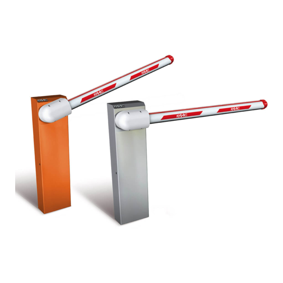
Summary of Contents for FAAC 615BPR Series
- Page 1 615BPR 615BPR...
-
Page 2: Table Of Contents
Index EC MACHINE DIRECTIVE COMPLIANCE DECLARATION ....................p. 2 IMPORTANT NOTICE FOR THE INSTALLER ........................... p. 2 1. DESCRIPTION AND TECHNICAL SPECIFICATIONS ......................p. 3 1.1. MAXIMUM USE CURVE ............................p. 3 2. ELECTRICAL DEVICES (standard system) ........................p. 4 3. -
Page 3: Ec Machine Directive Compliance Declaration
16) Each installation must be fitted with at least one fashing light (e.g. 4) Keep these instructions for future reference. FAAC LAMP, MINILAMP etc) as well as a warning plate suitably fixed to the gate, besides the safety devices as per point 15. above. -
Page 4: Description And Technical Specifications
Absorbed power (W) The 615BPR automatic system was designed and built for Type of oil FAAC HP OIL controlling vehicle access. Do not use for any other purpose. Oil quantity (Kg) Winding 120°... -
Page 5: Electrical Devices (Standard System)
2. ELECTRICAL DEVICES (standard system) 615BPR actuator Photocells Key push-button Flashing lamp Receiver fig.4 1) To lay cables, use adequate rigid and/or fig.5 flexible tubes. 2) Always separate connection cables of low 4.3. MECHANICAL INSTALLATION voltage accessories from 230V~ supply 1) Remove the cover, unscrewing the screws securing it cables. -
Page 6: Installing And Adjusting The Balancing Spring
CONVERTING FROM RIGHT-HAND TO LEFT-HAND 4.4. INSTALLING AND ADJUSTING THE BALANCING SPRING VERSION 1) Check if the balancing spring matches the type of Procedure for converting a right-hand version to left-hand: beam installed: see chapter 8. 2) Take the bronze bush (fig.7 ref.1) from the supplied Release the operator. -
Page 7: Start-Up
5. START-UP 6. MANUAL OPERATION If the barrier has to be moved manually due to a power cut 5.1. ADJUSTING TRANSMITTED TORQUE or fault of the automatic system, use the release device as To set the hydraulic system controlling transmitted power, follows: turn the two by-pass screws (fig.9 ref.B). -
Page 8: Available Accessories
(fig.18). To top-up, unscrew the filling plug (fig.18) and pour oil to MAX level on the stick. Use only FAAC HP OIL oil and no other. Dimensions are in mm. fig. 15 To position the fork support foundation plate, refer to fig.15 where: fig. - Page 9 USER’S OPERATING MANUAL An opening pulse given during re-closing always reverses 615BPR AUTOMATIC SYSTEM movement. A stop pulse (if supplied) always stops movement. GENERAL SAFETY REGULATIONS For details on barrier behaviour in different function logics, consult the installation Technician. If correctly installed and used, the 615BPR automatic The automatic systems include safety devices (photocells) system ensures a high degree of safety.
- Page 10 Le descrizioni e le illustrazioni del presente manuale non sono impegnative. La FAAC si riserva il diritto, lasciando inalterate le caratteristiche essenziali dell’apparecchiatura, di apportare in qualunque momento e senza impegnarsi ad aggiornare la presente pubblicazione, le modifiche che essa ritiene convenienti per miglioramenti tecnici o per qualsiasi altra esigenza di carattere costruttivo o commerciale.


Need help?
Do you have a question about the 615BPR Series and is the answer not in the manual?
Questions and answers