Table of Contents
Advertisement
Quick Links
Quick Guide
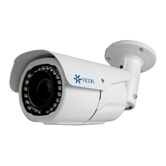
V988B
Network 4K Bullet Camera
Vicon Industries Inc. does not warrant that the functions contained in this equipment will
meet your requirements or that the operation will be entirely error free or perform
precisely as described in the documentation. This system has not been designed to be
used in life-critical situations and must not be used for this purpose.
Docum
e nt Number: 8009-8302-20-00 Product specifications subject to change without
notice. Issued: 6/18 Copyright © 2018 Vicon Industries Inc. All rights reserved.
XX302-20-00
Vicon Industries Inc.
Tel: 631-952-2288)
Fax: 631-951-2288
Toll Free: 800-645-9116
24-Hour Technical Support:
800-34-VICON
Advertisement
Table of Contents

Related Manuals for Vicon V988B


Summary of Contents for Vicon V988B
- Page 1 Network 4K Bullet Camera XX302-20-00 Vicon Industries Inc. Vicon Industries Inc. does not warrant that the functions contained in this equipment will Tel: 631-952-2288) meet your requirements or that the operation will be entirely error free or perform Fax: 631-951-2288 precisely as described in the documentation.
-
Page 2: Explanation Of Graphical Symbols
WARNING TO REDUCE THE RISK OF FIRE OR ELECTRIC SHOCK, DO NOT EX- POSE THIS PRODUCT TO RAIN OR MOISTURE. DO NOT INSERT ANY METALLIC OBJECT THROUGH THE VENTILATION GRILLS OR OTHER OPENINGS ON THE EQUIPMENT. CAUTION CAUTION RISK OF ELECTRIC SHOCK DO NOT OPEN WARNING: TO REDUCE THE RISK OF ELECTRIC SHOCK, DO NOT REMOVE COVER (OR BACK). -
Page 3: Fcc Compliance Statement
FCC COMPLIANCE STATEMENT This device complies with Part 15 of the FCC Rules. Operation is subject to the following two conditions: (1) this device may not cause harmful interference, and (2) this device must accept any interference received, including interference that may cause undesired operation. FCC INFORMATION: This equipment has been tested and found to comply with the limits for a Class A digital device, pursuant to Part 15 of... - Page 4 IMPORTANT SAFETY INSTRUCTIONS Read these instructions. Keep these instructions. Heed all warnings. Follow all instructions. Do not use this apparatus near water. Clean only with dry cloth. Do not block any ventilation openings. Install in accordance with the manufacturer’s instructions. Do not install near any heat sources such as radiators, heat registers, stoves, or other apparatus (including amplifiers) that produce heat. Do not defeat the safety purpose of the polarized or grounding‐type plug. A polarized plug has two blades with one wider than the other. A grounding type plug has two blades and a third grounding prong. The wide blade or the third prong is provided for your safety. If the provided plug does not fit into your outlet, consult an electrician for replacement of the obsolete outlet. 10. Protect the power cord from being walked on or pinched particularly at plugs, convenience receptacles, and the point where they exit from the apparatus. 11. Only use attachments/accessories specified by the manufacturer. 12. Use only with the cart, stand, tripod, bracket, or table specified by the manufacturer, or sold with the apparatus. When a cart is used, use caution when moving the cart/apparatus combination to avoid injury from tip‐over. 13. Unplug this apparatus during lightning storms or when unused for long periods of time. 14. Refer all servicing to qualified service personnel. Servicing is required when the apparatus has been damaged in any way, such as power‐supply cord or plug is damaged, liquid has been spilled or objects have fallen into the apparatus, the apparatus has been exposed to rain or moisture, does not operate normally, or has been dropped. 15. CAUTION – THESE SERVICING INSTRUCTIONS ARE FOR USE BY QUALIFIED SERVICE PERSONNEL ONLY. TO REDUCE THE RISK OF ELECTRIC SHOCK DO NOT PERFORM ANY SERVICING OTHER THAN THAT CONTAINED IN THE OPERATING INSTRUCTIONS UNLESS YOU ARE QUALIFIED TO DO SO. 16. Use satisfy clause 2.5 of IEC60950‐1/UL60950‐1 or Certified/Listed Class 2 power source only. 17. ITE is to be connected only to PoE networks without routing to the outside plant.
- Page 5 Introduction Vicon’s V988B-W311MIR HD IP Bullet Camera is designed for performance in demanding security installations. The camera provides 4K (8 MP) resolution with a 3.6-11 mm motorized varifocal lens. The camera offers IR illuminators that provide superior images in low-light environments.
-
Page 6: Installation
Installation For the network camera to operate, it is necessary to connect a network cable for data transmission and power connection from a power adapter. Depending on operation methods, it is possible to connect an alarm cable. 2.1 Overview • Dimension Dimensions Unit: mm • Extension Cable Item Description Ethernet, RJ-45 port compatible RJ-45 with 10/100Mbps PoE Modular Jack DC Jack Main Power, DC Jack, 12 VDC AI: Alarm In... - Page 7 • Installing Camera To mount the bullet camera, fix the base of the camera with the three screws provided in the accessory kit.
- Page 8 2.2 Connection • Micro SD memory slot on the bottom board Remove the cap at bottom of the camera to insert the SD memory card. • Connecting to the RJ-45 Connect a standard RJ-45 cable to the network port of the network camera. Generally a cross-over cable is used for direct connection to PC, while a direct cable is used for connection to a hub.
-
Page 9: Resetting To The Factory Default Settings
2.3 Resetting to the Factory Default Settings > > To reset the network camera to the original factory settings, go to the Setup System Maintenance web > page (described in “System Maintenance” of User Manual) or use the Reset button on the network camera inside the bottom cap. -
Page 10: Network Connection & Ip Assignment
2.4 Network Connection & IP Assignment The network camera is designed for use on an Ethernet network and requires an IP address for access. Most networks today have a DHCP server that automatically assigns IP addresses to connected devices. By the factory default, your camera is set to obtain the IP address automatically via DHCP server. If your network does not have a DHCP server the network camera will use 192.168.1.100 as the default IP address. If DHCP is enabled and the product cannot be accessed, run the “Smart Manager” utility to search and allocate an IP address to your products, or reset the product to the factory default settings and then perform the installation again. The utility can be found on the Vicon website www.vicon‐security.com, on the Software Downloads page for Vicon cameras. 1) Connect the network camera/device to the network and power up. > > > 2) Start SmartManager utility (Start All programs SmartManager SmartManager); the main window displays. -
Page 11: Operation
3. Operation The network camera can be used with Windows® operating system and browsers. The recommended browsers are Internet Explorer®, Safari®, Firefox®, Opera® and Google® Chrome® with Windows. Note: To view streaming video in Microsoft® Internet Explorer, set your browser to allow ActiveX controls. Access from a Browser 1. Start a browser (i.e., Internet Explorer). 2. -
Page 12: Setting The Admin Password Over A Secure Connection
> > > to allow access to the network cam- era. This is enabled from Setup System Network NAT. For more information, refer to section “System>Network>NAT” of the User manual. Setting the admin password over a secure connection To gain access to the product, the password for the default administrator user must be set. This is done in the “Admin Password”... -
Page 13: Live View Page
Live View Page The Live View page provides several screen modes. Select the most suitable mode in accordance with your PC specifications and monitoring purposes. General controls Live View Page Playback Page Setup Page Help Page The video drop-down list allows you to select a customized or pre-programmed video >... -
Page 14: Video Streams
The Manual Trigger button activates a pop-up window to manually start or stop the event. The Remote Focus button enables users to adjust focus and zoom remotely via network (motorized lens models only). The Fine Focus (one push focus) button readjusts focus automatically to set the focus to the optimum position (motorized lens models only). - Page 15 4) Focus and Zoom Control (motorized lens models only). You can control Zoom and Focus from the Live View screen. Press the button on the left top in the Live View screen to activate the Zoom and Focus control panel. •...
- Page 16 VICON INDUSTRIES INC. For office locations, visit the website: www.vicon-security.com...
Need help?
Do you have a question about the V988B and is the answer not in the manual?
Questions and answers