Table of Contents
Advertisement
Quick Links
Advertisement
Table of Contents

Subscribe to Our Youtube Channel
Related Manuals for Major tech MT935


Summary of Contents for Major tech MT935
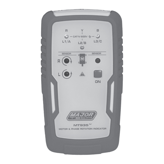
- Page 1 INSTRUCTION MANUAL MT935 MOTOR & PHASE ROTATION INDICATOR...
- Page 2 Page no Contents 1. Introduction..................3 2. Symbols..................3 3. Safety Information................3 4. Accessories Included................4 5. Meter Description................4 6. Operation ..................4 6.1. Determine Rotary Field Direction..........4 6.2. Non-Contact Rotary Field Indication...........5 6.3. Determine the Motor Connection..........6 6.4. Magnetic Field Direction............6 7. Battery Replacement................6 8.
- Page 3 • Adhere to local and national safety codes. • Individual protective equipment must be used to prevent shock and injury. • Using this meter in a manner not specified by Major Tech may impair safety features/protection provided by the equipment. • Avoid working alone.
- Page 4 • Verify operation prior to measuring hazardous voltages (voltages above 30V AC RMS, 42V AC peak and 60V DC). • Do not use the meter with any of the parts removed. • Do not use the meter around explosive gas, vapor, or dust. •...
- Page 5 6.2. Non-Contact Rotary Field Indication 1. Disconnect all test leads from the Meter. 2. As shown in Figure 2, position the MT935 on the motor so that it is parallel to the length of the motor shaft, the meter should be at least 1 inch away from the motor.
- Page 6 6.3. Determine the Motor Connection 1. Connect one end of the test leads to the Meter, make sure the L1, L2 and L3 test leads are connected to the corresponding jack. 2. Connect the alligator clamps to the other end of the test leads. 3.
- Page 7 8.2. Non-Contact Rotary Field Indication Function Range Frequency Range (fn) 2 to 400Hz 8.3. Determine the Motor Connection Function Range Nominal Test Voltage (U me) 1 to 400V AC Nominal Test Current (In per phase) Less than 3.5mA Frequency Range (fn) 2 to 400Hz 8.4.
- Page 8 MAJOR TECH (PTY) LTD South Africa Australia www.major-tech.com www.majortech.com.au sales@major-tech.com info@majortech.com.au...
Need help?
Do you have a question about the MT935 and is the answer not in the manual?
Questions and answers