
Related Manuals for Advantech IACP-4000 Series


Summary of Contents for Advantech IACP-4000 Series
- Page 1 IACP-4000 Series 5.7" VGA TFT LCD Pentium 4/ Celeron D 4U Industrial Workstation with 7xISA/PCI Slots Users Manual...
- Page 2 Copyright This document is copyrighted, 2008, by Advantech Co., Ltd. All rights are reserved. Advantech Co., Ltd. reserves the right to make improve- ments to the products described in this manual at any time without notice. No part of this manual may be reproduced, copied, translated or transmit- ted in any form or by any means without the prior written permission of Advantech Co., Ltd.
- Page 3 Additional Information and Assistance Step 1. Visit the Advantech web site at www.advantech.com where you can find the latest information about the product. Step 2. Contact your distributor, sales representative, or Advantech's customer service center for technical support if you need addi- tional assistance.
- Page 4 The sound pressure level at the operator's position according to IEC 704-1:1982 is no more than 70 dB (A). DISCLAIMER: This set of instructions is given according to IEC 704-1. Advantech disclaims all responsibility for the accuracy of any statements contained herein.
-
Page 5: Table Of Contents
Specifications ..............2 1.2.1 General ................2 1.2.2 System Hardware ............3 1.2.4 Environment ..............3 IACP-4000 Series List ............4 Dimensions................ 4 Exploded Diagram............. 5 Figure 1.1:Exploded Diagram ........5 Accessory Packing list ............5 Chapter 2 System Setup............ 8 System Installation ............ - Page 6 IACP-4000 User Manual...
- Page 7 General Information Chapter 1...
-
Page 8: Chapter 1 General Information
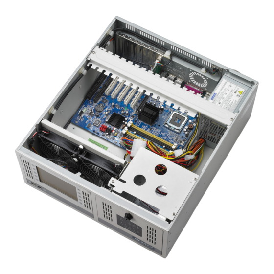
Chapter 1 General Information 1.1 Introduction IACP-4000 is a 4U height 14-slot rackmount IPC chassis with ATX industrial motherboard inside which equipped 5.7" TFT LCD (4000D series)for varied application purpose, high-efficiency 300W ATX with PFC (power factor correction) power supply and maintainable dual cool- ing fan. -
Page 9: System Hardware
1.2.2 System Hardware • Audio Ports 1 x Mic-in, 1 x Line-out, 1 x CD Audio in, 1 x Line out, 1 x S/PDIF • Chipset Intel 82915GV GMCH • CPU Intel µFC-LGA 775 socket • Expansion Slots 1 PCI Express x 16, 5 PCI slots (PCI Rev. -
Page 10: Iacp-4000 Series List
1.3 IACP-4000 Series List • IACP-4000D-A0AE 5.7" VGA TFT LCD Pentium/Celeron D 4U Rack Industrial Workstation with 5 PCI/ 2 ISA/ 1 ADD2 Slots • IACP-4000G-A0AE IACP-4000D-A0AE without display • IACP-4000D-A2AE 5.7" VGA TFT LCD Core 2 Quad / Core... -
Page 11: Exploded Diagram
Figure 1.1: Exploded Diagram 1.6 Accessory Packing list • CABLE 6P-6P-6P PS/2 KB & MOUSE 20cm • Simplified Chinese Manuel IACP-4000 Series V1.0 • China RoHS IACP-4000 Series 1st Ed. • CD-ROM IPPC Series V3.2 • SATA cable and SATA 4P power Cable •... - Page 12 For IACP-4000D series only: • CABLE 6P/6P 20cm Mini DIN (M) for AWS-8421T • CABLE 15/15P 20cm for AWS-8259 VGA Port Note: This model supports from Celeron D 336 2.8GHz up to Intel Pentium 4 640 SL7Z8 CHINA 3.20GHZ/2M/800/04A 5529B102 L2- Cache, LGA775Pkg FSB CPU IACP-4000 User Manual...
- Page 13 System Setup Chapter 2...
-
Page 14: Chapter 2 System Setup
Chapter 2 System Setup 2.1 System Installation WARNING: Before starting the installation process, be sure to shut down all power from the chassis. Do this by turning off the power switch, and unplugging the power cord from the power outlet. When in doubt, consult with an experienced technician. -
Page 15: Chassis Front And Rear Sections
2.1.3 Chassis Front and Rear Sections The front panel switches behind the door are used for system power, sys- tem reset 1, system reset 2 (option), alarm reset and power switch. The door cover is on the left side of the door cover, where the system LED sta- tus and key lock switch are located. - Page 16 System Reset 1: Press this switch to reinitialize the system. This is the same as the hardware reset button. (Default setting) System Reset 2: Press this switch to reinitialize the second system. (Optional) Alarm Reset Switch: Press this switch to suppress or stop an audible alarm.
-
Page 17: Drive Bay Installation
Connect the disk drive power and signal cables. 2.1.5 Motherboard Installation & Information For the more detailed information of the IACP-4000 Series motherboard, please refer to the below path in the user CD : \2063615201_V3.1\System Drivers\IACP-4000\Motherboard Driver\i915GV-INA Motherboard... -
Page 18: Led Indicators
2.2 LED Indicators 2.2.1 System Status LED The System Status LED shows as follows: When the PWR LED is RED, it indicates a redundant power supply fail- ure. To stop the alarm buzzer, press the Alarm Reset button. Please check out the redundant power supply right away and replace failure power sup- ply module with a good one. -
Page 19: Power Status Led
2.2.2 Power Status LED Power Status LED indicates the status of the backplane voltage signals. When a LED fails to light, it indicates a problem with one of the voltage signals. An audible alarm is sounded. Check to make sure that the power supply connector is properly attached to the backplane. -
Page 20: Cooling Fan & Filter
2.4 Cooling Fan & Filter There are two cooling fans located inside the chassis. When one cooling fan breaks down, the system sounds a continuous alarm. To disable the alarm, press the Alarm Reset switch and replace the fan immediately. To replace a defective fan, refer to the figures below. - Page 21 Alarm Board Chapter 3...
-
Page 22: Chapter 3 Alarm Board
Chapter 3 Alarm Board The alarm board is located under the cooling fan section. It gives an audible alarm when: Any power supply module of redundant power supply fails One of the cooling fans fai1s Temperature inside the chassis rises A problem occurs in one of the backplane voltage levels The detailed layout and specification of the alarm board are as follows: 3.1 Alarm Board Layout... -
Page 23: Alarm Board Specification
3.2 Alarm Board Specification Input Power: +5V , +12V Input Signals: • 7 FAN connectors (GND_+12V_FAN) • One thermal board connector (up to 8 thermal boards in a roll) • One power good input • One alarm reset input. • One voltage signal connector (connect from backplane, includes ±12V , ±5V , 3.3V) •... - Page 24 CN1 : External Power Connector, standard mini 4 Pin power connector Pin 1 : +12V, 2A current maximum Pin 2 : GND Pin 3 : GND Pin 4 : +5V, 2A current maximum CN2 : 10/100M LAN Connector Pin 1 : SPLED Pin 2 : TERMPLANE Pin 3 : RX+ Pin 4 : RX-...
- Page 25 Pin 1 : SIN Pin 2 : SOUT Pin 3 : CTS# Pin 4 : DCD# Pin 5 : RTS# Pin 6 : DTR# Pin 7 : DSR# Pin 8 : ID 0 Pin 9 : ATX ON Pin 10 : DO 4 Pin 11 : GND Pin 12 : DO 3 Pin 13 : Watchdog IN...
- Page 26 Pin 1 : Power GOOD A Pin 2 : GND CN18 : LED Board Connector Pin 1 : GND Pin 2 : +5V Signal Pin 3 : +12V Signal Pin 4 : -5V Signal Pin 5 : -12V Signal Pin 6 : HDD Signal Pin 7 : Power Good Signal Pin 8 : Power Fail Signal Pin 9 : Temperature Good Signal...
-
Page 27: Switch Setting
3.3 Switch Setting Fan Number Setting Thermal Board Temperature Setting Chapter 3... -
Page 28: Thermal Sensor
3.4 Thermal Sensor There is a temperature sensor inside the chassis, See Figure 3.4-1.to find the location. When the temperature rises, the temperature sensor sends a signal to the alarm board and a continuous alarm is sounded. To stop the alarm, press the Alarm Reset Switch at the Front Panel.
Need help?
Do you have a question about the IACP-4000 Series and is the answer not in the manual?
Questions and answers