Table of Contents
Advertisement
Quick Links
Advertisement
Table of Contents

Subscribe to Our Youtube Channel
Related Manuals for AMS TSL2584TSV


Summary of Contents for AMS TSL2584TSV
- Page 1 User Guide TSL2584TSV EVM TSL2584TSV Light-To-Digital Ambient Light Version 1.1...
-
Page 2: Table Of Contents
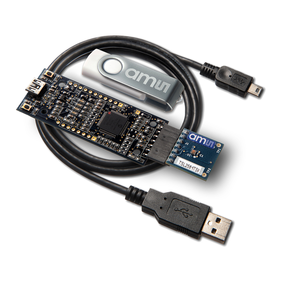
Contents Establishing basic functionality .................... 4 TSL2584TSV EVM graphical user interface (GUI) .............. 4 Software overview ........................ 4 2.1.1 Device ID Information......................5 2.1.2 Log Status and Control Information ..................6 2.1.3 System Menus ........................6 2.1.4 System Level Controls ......................8 2.1.5... - Page 3 Quick Start Guide (QSG). This will load the required driver for the USB interface and also the control software and graphical user interface (GUI). The hardware consists of the EVM Controller v2.1a or v2.1c, the TSL2584TSV EVM daughterboard, a USB interface cable and USB Memory Stick.
-
Page 4: Establishing Basic Functionality
C:\Program Files\ams\TSL2584TSV_EVM Windows 32 bit operating systems C:\Program Files (x86)\ams\TSL2584TSV_EVM Windows 64 bit operating systems A different install path may be selected by the user. When started, the TSL2584TSV window will open on the PC. The balance of this document identifies and describes the controls available on the GUI. In combination with the TSL2584TSV datasheet, the QSG and application notes available on the ams website, www.ams.com. -
Page 5: Device Id Information
The main window for the TSL2584TSV is shown below. Clicking on the red “X” will close the window and terminate the application. The checkboxes near the top of the window power on the chip and enable the ALS function. The ALS tab contains controls for the remaining functions and displays status and data from the device as it operates. -
Page 6: Log Status And Control Information
2.1.2 Log Status and Control Information The lower right corner of the window contains status information and controls for the logging function: This section contains two text boxes that are stored in the log file data and used to build the file name for the log file. - Page 7 2.1.3.2 Log Menu The Log menu is used to control the logging function and to save the log data to a file. Log data is accumulated in memory until it is discarded or written to a data file. Click Start Logging to start the logging function. Each time the program polls the ALS information from the device, it will create a new log entry showing the raw data values, the calculated lux value, the values of various control registers, and the values entered by the user into the text fields near the bottom right corner of the window.
-
Page 8: System Level Controls
TSL2584TSV device. The Power-On checkbox controls the PON function of the TSL2584TSV. When this box is checked, the power is on and the device can operate. When this box is unchecked, the power is off and the device will not operate (The control registers can still be written, but the device will not function). - Page 9 2.1.5.1 ALS Controls The top left corner of the ALS tab contains two controls; one to set the ALS integration time and another to control the ALS gain. The ITIME control sets the time of the ALS integration. ITIME can be adjusted in 2.72ms steps. This register functions as a count-down value so ITIME=255 is the minimum integration time (2.72ms) and ITIME=1 is the maximum integration time (693.6ms).
-
Page 10: Resources
TSL2584TSV EVM Quick Start Guide (QSG) Designer’s Notebooks For additional information regarding the TSL2584TSV, please refer to the datasheet. For information regarding the installation of the TSL2584TSV EVM host application software please refer to the TSL2584TSV EVM Quick Start Guide.
Need help?
Do you have a question about the TSL2584TSV and is the answer not in the manual?
Questions and answers