
Related Manuals for AMS TCS3720


Summary of Contents for AMS TCS3720
- Page 1 User Guide UG001018 TCS3720 TCS3720 EVM ALS/Color and Proximity Sensor for Behind OLED Applications v1-00 • 2021-Aug-17...
-
Page 2: Table Of Contents
Document Feedback TCS3720 Content Guide Content Guide Device ID Information ......... 11 Introduction ........3 Log Status and Control Information .... 12 Kit Content ............ 3 “Configuration” Tab ........13 Ordering Information ........3 “ALS” Tab ........... 16 “Prox” Tab ........... 18 Getting Started ...... -
Page 3: Introduction
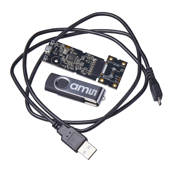
Document Feedback TCS3720 Introduction Introduction The TCS3720 features ambient light, color (RGB) sensing and proximity detection. The device integrates two advanced emitter drivers within a compact 3.34 mm × 1.36 mm × 0.6 mm OLGA package. Kit Content Figure 1:... -
Page 4: Getting Started
The balance of this document identifies and describes the controls available on the GUI. In combination with the TCS3720 datasheet, the QSG and application notes available on the ams OSRAM website, www.ams-osram.com, there should be enough information to allow evaluation of the TCS3720 device. -
Page 5: Hardware Description
TCS3720 Hardware Description Hardware Description The hardware consists of the EVM Controller, the TCS3720 EVM daughter card, and a USB interface cable. The EVM controller board provides power and I C communication to the daughter card through a seven-pin connector. When the EVM controller is connected to the PC through USB, a green LED lights to indicate the system is receiving power. -
Page 6: Software Description
Document Feedback TCS3720 Software Description Software Description The main window (Figure 3) contains the system menus, system level controls, device information and logging status. The box on the left side of the window controls various system-wide parameters and functions. The Configuration tab contains controls to setup both ALS and Proximity detection parameters. -
Page 7: System Menus
Document Feedback TCS3720 Software Description the USB, a green LED lights to indicate the USB cable is connected and providing power to the system. The LED will remain lit until the any software application opens the controller. The light will then be switched off so that it will not interfere with any light measurements. - Page 8 Document Feedback TCS3720 Software Description 4.2.2 Prox Log Menu The Prox Log menu controls the logging of Proximity data and saves the log data to a file. Log data accumulates in memory until discarded or written to a data file.
- Page 9 Document Feedback TCS3720 Software Description Figure 6: ALS Log Menu Click Start Logging ALS to start the logging function. Each time the program receives a new set of ALS data from the device, it creates a new log entry showing the raw data values, the values of various control registers, and the values entered by the user into the text fields near the bottom right corner of the window.
-
Page 10: System Level Controls
Immediately below the top menu bar there are checkboxes used to control the system level functions of the TCS3720 device. The Power On checkbox controls the PON function of the TCS3720. When this box is checked, the oscillator is on and the device is running measurements according the settings in the System Level Controls and the Configuration tab. -
Page 11: Auto Polling
Auto Polling The application automatically polls the TCS3720 raw Prox data and reads the ALS data from the FIFO, depending on the Enable bits. The Poll Interval at the right upper corner of the form displays the actual time between reads of the device. -
Page 12: Log Status And Control Information
Document Feedback TCS3720 Software Description Log Status and Control Information The lower right corner of the window contains status information and controls for the logging function: Figure 9: Logging Status This section contains text boxes that are stored in the log file data and used to build the file name for the log file. -
Page 13: Configuration" Tab
Document Feedback TCS3720 Software Description “Configuration” Tab The main portion of the screen contains a tab labeled Configuration. Figure 10: Configuration Tab 4.7.1 Configuration Controls The Configuration Tab contains controls that affect operation of the Prox and ALS functions. The ALS-related tabs are toward the right side of the tab and the Prox-related tabs are on the left. - Page 14 Document Feedback TCS3720 Software Description The PLDRIVE box contains a group of controls which set the drive current for the VCSELs. ● Step specifies the step size in milliamps for both of the VCSEL drivers. You may select 0.5 mA, 1.0 mA, 1.5 mA, or 2.0 mA.
- Page 15 Document Feedback TCS3720 Software Description The HW Average control causes the device to average multiple prox integrations for each PDATA output. Using this pull-down menu, you can select to average 2, 4, 8, or 16 values, or disable the hardware averaging function. If enabled, the hardware will use the PTIME value to control how fast the selected number of cycles is collected and will then set PDATA to the average of the collected data.
-
Page 16: Als" Tab
Document Feedback TCS3720 Software Description Checking the Residual Bits checkbox enables appending additional bits to the ALS data values, to increase their accuracy. See the datasheet for an explanation of the effect that this has on the data format and the interpretation of the ALS channel values. - Page 17 Document Feedback TCS3720 Software Description column will always display 0. If ASP1/ASP2 operation is active (ASP1 > 0) then the data is displayed in both columns. The ALS data is read from the FIFO until all of the data for the configured ATIME value is read. It is then displayed on the screen.
-
Page 18: Prox" Tab
The actual polling interval is shown in the upper right-hand corner of the screen. ● PDATA displays the latest polled Proximity channel count. Note that the TCS3720 can be configured to run much faster than this program can run, so this field will not display every PDATA value from the device. - Page 19 Document Feedback TCS3720 Software Description ● VSYNC indicates the most recent VSYNC period detected. This value is only valid if a VSYNC signal is present. ● VSYNC Lost will be marked when the device detects a missing VSYNC signal ●...
-
Page 20: Resources
Resources For additional information regarding the TCS3720, please refer to the datasheet. For information regarding the installation of the TCS3720 EVM host application software please refer to the TCS3720 EVM Quick Start Guide. Designer’s Notebooks dealing with various aspects of optical measurement and optical measurement applications are available. -
Page 21: Revision Information
Document Feedback TCS3720 Revision Information Revision Information Changes from previous version to current revision v1-00 Page Initial version ● Page and figure numbers for the previous version may differ from page and figure numbers in the current revision. ● Correction of typographical errors is not explicitly mentioned. -
Page 22: Legal Information
AG shall not be liable to recipient or any third party for any damages, including but not limited to personal injury, property damage, loss of profits, loss of use, interruption of business or indirect, special, incidental or consequential damages, of any kind, in connection with or arising out of the furnishing, performance or use of the technical data herein.
Need help?
Do you have a question about the TCS3720 and is the answer not in the manual?
Questions and answers