Table of Contents
Advertisement
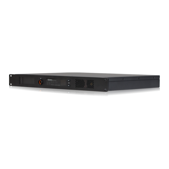
USER MANUAL
H R106X DIGITAL REPEATER
www.hytera.us info@hytera.us
(C) 2022 Hytera Communications Ltd. All rights reserved.
Hytera US Inc.
Hytera Canada
8 Whatney,
100 Leek Crescent, Unit 11
Irvine, CA 92618
Richmond Hill, ON L4B 3E6
(949) 326-5742
(905) 305-7545
www.hytera.ca info@hytera.ca
1363 Shotgun Road,
Sunrise, FL 33326
(954) 846-1011
Advertisement
Table of Contents

Related Manuals for Hytera HR106X


Summary of Contents for Hytera HR106X
- Page 1 Hytera Canada 8 Whatney, 100 Leek Crescent, Unit 11 Irvine, CA 92618 Richmond Hill, ON L4B 3E6 (949) 326-5742 (905) 305-7545 www.hytera.ca info@hytera.ca 1363 Shotgun Road, Sunrise, FL 33326 (954) 846-1011 www.hytera.us info@hytera.us (C) 2022 Hytera Communications Ltd. All rights reserved.
- Page 2 Preface Welcome to the world of Hytera and thank you for purchasing this product. This manual includes a description of the functions and step-by-step procedures for use. To avoid bodily injury or property loss caused by incorrect operation, please carefully read the Safety Information Booklet before use.
- Page 3 Copyright Information Hytera is the trademark or registered trademark of Hytera Communications Corporation Limited (the Company) in PRC and/or other countries or areas. The Company retains the ownership of its trademarks and product names. All other trademarks and/or product names that may be used in this manual are properties of their respective owners.
- Page 4 and 2.1091 American National Standards Institute (ANSI) / Institute of Electrical and Electronic Engineers (IEEE) C95. 1:2005; Canada RSS102 Issue 5 March 2015 Institute of Electrical and Electronic Engineers (IEEE) C95.1:2005 Edition Compliance with RF Exposure Standards To control your exposure and ensure compliance with the occupational/controlled environment exposure limits, this equipment should be operated with minimum distance 45 cm between the radiator &...
- Page 5 limits in the above standards and guidelines, users should always adhere to the followings: Gain of antenna must not exceed 5 dBi (indoor) or 10 dBi (outdoor). Install the antenna at least 105 cm (indoor) or 180 cm (outdoor) away from your body, in accordance with the ...
-
Page 6: Table Of Contents
Contents Documentation Information ........................1 1. Packing List ............................2 2. Product Overview ..........................3 2.1 Front Panel ............................3 2.2 Rear Panel ............................3 2.2.1 Basic Version ........................... 3 2.2.2 Advanced Version ........................4 2.3 Internal Parts ............................. 5 2.3.1 Basic Version ........................... - Page 7 5.3.2 Solution..........................13 5.4 Over-Voltage or Under-Voltage Alarm ..................... 13 5.4.1 Description ..........................13 5.4.2 Solution..........................14 5.5 VSWR Alarm............................ 14 5.5.1 Description ..........................14 5.5.2 Solution..........................14 5.6 Coprocessor Over-Temperature Alarm .................... 15 5.6.1 Description ..........................15 5.6.2 Solution..........................15 5.7 Network IP Conflict Alarm ........................
-
Page 8: Documentation Information
Documentation Conventions Icon Conventions Icon Description Indicates references that can further describe the related topics. Indicates situations that could cause data loss or equipment damage. Indicates situations that could cause major personal injury or even death. Notational Conventions Item Description Example To save the configuration, click Apply. -
Page 9: Packing List
1. Packing List Please unpack carefully and check that you have received the following items. If any item is missing or damaged, contact your dealer. Item Quantity (PCS) Item Quantity (PCS) Repeater Documentation Kit Power Cord Figures in this manual are for reference only. ... -
Page 10: Product Overview
2. Product Overview 2.1 Front Panel Part Name Part Name Air Inlet for PA Timeslot A RX Indicator Volume/Channel + Key Timeslot A TX Indicator Volume/Channel – Key Analog Mode Indicator Seven-segment Display Digital Mode Indicator Alarm Indicator Audio/Programming Interface Timeslot B RX Indicator Air Inlet for Power Supply Timeslot B TX Indicator... -
Page 11: Advanced Version
2.2.2 Advanced Version Part Name Part Name TX Antenna Connector USB Connector Monitor/Tuning Interface DC Power Inlet Accessory Connector AC Power Inlet RX Antenna Connector AC Power Switch Ethernet Interface 1 Ground Screw Ethernet Interface 2 In routing mode, the Ethernet interface 1 and Ethernet interface 2 must serve as LAN port and WAN port respectively. -
Page 12: Internal Parts
2.3 Internal Parts 2.3.1 Basic Version Part Name Part Name PA Module Wind Scooper Main Board Network Board Control Panel Power Supply Module Float Charging Board... -
Page 13: Advanced Version
2.3.2 Advanced Version Part Name Part Name PA Module Wind Scooper Main Board Coprocessor Control Panel Power Supply Module Float Charging Board... -
Page 14: Installation
3. Installation To ensure optimum performance and reliability of the repeater, read the following instructions carefully. 3.1 Installation Requirements 3.1.1 Environmental Conditions The repeater must be installed in a dry and well-ventilated place. The operating temperature ranges from –30°C to +60°C, and the relative humidity is 95%. -
Page 15: Post-Installation Check
If the repeater is installed in outdoor environments with frequent thunderstorms, such as the top of mountains or buildings, you must install an external lightning protection module (optional) on the network interface. Connect the antenna, feed line, ground cable, and power cord to the repeater. You must purchase the antenna and feed lines separately. -
Page 16: Basic Operations
4. Basic Operations 4.1 Turning On or Off the Repeater If the repeater is connected to a DC power supply, press the power switch on the DC power supply to turn on or off the repeater. After turn-on, if the power supply indicator turns red, the repeater goes into locked status. You must switch off the DC power supply for four seconds, and then switch on the power supply again. -
Page 17: Network Interface
Indicator Description Repeater Status Digital mode: The repeater is transmitting on timeslot A. Analog mode: The repeater is receiving. Timeslot A RX Green Digital mode: The repeater is receiving on timeslot A. Timeslot B TX Digital mode: The repeater is transmitting on timeslot B. Timeslot B RX Green Digital mode: The repeater is receiving on timeslot B. -
Page 18: Alarm Information
5. Alarm Information With the Alarm feature enabled by your dealer, the repeater can automatically trigger an alarm if it does not work well. When the alarm is active, the alarm indicator glows red and the alarm code appears on the display. The following table describes alarms in detail. -
Page 19: Low Forward Power Alarm
Alarm Alarm Name Description Code The repeater fails to work. At this time, if the Repeater Coprocessor over-temperature alarm Backup feature is enabled on the CPS, the repeater starts a backup. Network IP conflict alarm Network services of the repeater are unavailable. 5.1 Low Forward Power Alarm 5.1.1 Description When the repeater detects that the TX power is below the preset value of forward power, the alarm indicator glows... -
Page 20: Pa Over-Temperature Alarm
5.3 PA Over-Temperature Alarm 5.3.1 Description When the repeater detects that the internal temperature of the PA module exceeds the upper threshold, the alarm indicator glows red and the alarm code E6 appears on the display. At this time, the repeater stops transmission. 5.3.2 Solution Check whether the surface temperature of the PA module is over 120°C. -
Page 21: Solution
At this time, the repeater disables all features and does not supply power for all circuits excerpt the baseband board circuit. 5.4.2 Solution Use a voltmeter to check whether the DC or AC power ranges from 11 V to 15.6 V. If yes, proceed with Step 2. -
Page 22: Coprocessor Over-Temperature Alarm
5.6 Coprocessor Over-Temperature Alarm 5.6.1 Description When the advanced repeater detects that the temperature of the coprocessor exceeds 110°C, the alarm indicator glows red and the alarm code H1 appears on the display. At this time, the repeater fails to work. 5.6.2 Solution Take an appropriate measure to reduce the temperature lower than 100°C at the coprocessor. -
Page 23: Solution
glows red and the alarm code EE appears on the display. At this time, the repeater fails to work. When the repeater detects the invalid level, the repeater returns to normal use. When the level transforms between active and invalid status, the repeater restarts. ... -
Page 24: Troubleshooting
6. Troubleshooting Phenomena Analysis Solution The power cord may be disconnected Re-connect the power cord properly. or get loose. The repeater cannot be turned on. The fuse in the DC power cord may Replace the fuse. be damaged. The TX/RX frequency of the repeater may be inconsistent with that of the Reset the frequencies. -
Page 25: Care And Cleaning
7. Care and Cleaning To guarantee optimum performance as well as a long service life of the product, please follow the tips below. 7.1 Product Care Keep the product at a place of good ventilation and heat dissipation to facilitate normal work. ... -
Page 26: Optional Accessories
8. Optional Accessories Use the accessories specified by the Company only. Otherwise, we will not be liable for any loss or damage arising out of use of unauthorized accessories. Contact your local dealer for the optional accessories used with the product. -
Page 27: Abbreviations
Hytera Canada 8 Whatney, 100 Leek Crescent, Unit 11 Irvine, CA 92618 Richmond Hill, ON L4B 3E6 (949) 326-5742 (905) 305-7545 www.hytera.ca info@hytera.ca 1363 Shotgun Road, Sunrise, FL 33326 (954) 846-1011 www.hytera.us info@hytera.us (C) 2022 Hytera Communications Ltd. All rights reserved.
Need help?
Do you have a question about the HR106X and is the answer not in the manual?
Questions and answers