
Subscribe to Our Youtube Channel
Related Manuals for Hytera HR652


Summary of Contents for Hytera HR652
- Page 1 HR652 Digital Repeater User Manual © 2023 Hytera US Inc. All Rights Reserved. 8 Whatney, Irvine, CA 92618 info@hytera.us https:// www.hytera.us...
- Page 2 Preface Welcome to the world of Hytera and thank you for purchasing this product. This manual includes a description of the functions and step-by-step procedures for use. To avoid bodily injury or property loss caused by incorrect operation, please carefully read the Safety Information Booklet before use.
- Page 3 Copyright Information Hytera is the trademark or registered trademark of Hytera Communications Corporation Limited (the Company). The Company retains the ownership of its trademarks and product names. All other trademarks and/or product names that may be used in this manual are properties of their respective owners.
- Page 4 Operation is subject to the following two conditions: This device may not cause harmful interference. This device must accept any interference received, including interference that may cause undesired operation. Note: Any changes or modifications to this unit not expressly approved by the party responsible for compliance could void the user's authority to operate the equipment.
- Page 5 Specifications Parameter Description Digital Repeater: 400–470 MHz Frequency GPS L1 C/A, BDS B1I: 1559–1610 MHz High: 44 dBm Middle: 40 dBm Output Power Low: 30 dBm ...
-
Page 6: Table Of Contents
User Manual Contents Contents 1. Packing List .............................. 2 2. Product Layout ............................3 3. Precaution ..............................5 4. Installation ..............................6 4.1 Tools ..............................6 4.2 Procedure ............................. 6 4.2.1 (Optional) Install the Duplexer ....................6 4.2.2 Install the Repeater ........................8 5. - Page 7 Contents User Manual 7.7.2 Solution ............................ 18 7.8 Secondary Repeater Unregistered Alarm ..................18 7.8.1 Description ..........................18 7.8.2 Solution ............................ 19 7.9 Repeater Disabled Alarm ........................19 7.9.1 Description ..........................19 7.9.2 Solution ............................ 19 7.10 Low Forward Power Alarm ....................... 19 7.10.1 Description ..........................
- Page 8 User Manual Documentation Information Documentation Information Documentation Conventions Instruction Conventions Icon Description Indicates information that can help you make better use of your product. Indicates references that can further describe the related topics. Indicates situations that could cause data loss or equipment damage. Indicates situations that could cause minor personal injury.
-
Page 9: Packing List
Packing List User Manual 1. Packing List Unpack carefully and check that you have received the following items. If any item is missing or damaged, contact your dealer. Item Quantity (PCS) Item Quantity (PCS) Repeater Documentation Kit Power Cord Figures in this document are for reference only. -
Page 10: Product Layout
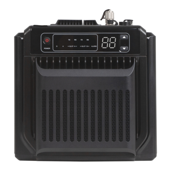
User Manual Product Layout 2. Product Layout Part Name Part Name Bottom cover Analog mode indicator USB port Timeslot A TX indicator TX/Duplexer antenna connector (UHF female) Timeslot A RX indicator Accessory connector Timeslot B TX indicator Ethernet port Timeslot B RX indicator Power inlet Alarm indicator RX antenna connector (SMA female) - Page 11 Product Layout User Manual Except that the low-power HR652 features no fan but the high-power HR65X features one, the other hardware of the two types is the same.
-
Page 12: Precaution
User Manual Precaution 3. Precaution Before installation and use, read the following instructions carefully. Install the repeater in a dry and well-ventilated place. Use the repeater in an environment where the temperature is between –30°C and +60°C and the relative humidity ... -
Page 13: Installation
Installation User Manual 4. Installation You can place the repeater on the desk, or install the repeater on the wall. 4.1 Tools Electric drill Screwdriver Wrench Anti-static gloves 4.2 Procedure 4.2.1 (Optional) Install the Duplexer Remove the bottom cover. Push the battery latch upwards ①... - Page 14 User Manual Installation Use the torx screwdriver to remove the two screws fixing the right decorative cover. Push the right decorative cover downwards ③ , and then remove the left decorative cover ④ , battery latch, and spring. Remove the rear housing. Use the Phillips screwdriver to remove the pan head screw.
-
Page 15: Install The Repeater
Installation User Manual Secure the duplexer to the mounting bracket with pan head screws (M 2.5 x 5). Connect the RF cable. 4.2.2 Install the Repeater Install the three pegs onto the fixing plate with three M3 screws at holes marked with "B". - Page 16 User Manual Installation Fix the fixing plate to the back of the repeater with four M4 screws. Install the repeater on the wall. Before installation, make sure the weight of the repeater is within the load bearing capacity of the wall. Hold the bracket horizontally to a proper position on the wall, and then mark the locations of the three holes Φ...
- Page 17 Installation User Manual Dock the three holes on the bracket with the three pegs on the back of the repeater.
-
Page 18: Basic Operation
Indication. The RSM is optional. Use the RSM specified by Hytera. PTT TX Channel Type and TX Contact Name are configured by the dealer. The repeater gives no indication or response if it detects no TX contact name on the current channel (digital... -
Page 19: Status Indication
Status Indication User Manual 6. Status Indication 6.1 LED Indicator Indicator Status Description Digital mode indicator Glows blue The repeater is in the digital mode. Analog mode indicator Glows orange The repeater is in the analog mode. An exception occurs (The seven-segment LED Alarm indicator Glows red displays the corresponding alarm code). - Page 20 User Manual Status Indication Channel Code Channel Code Description Indicates the current channel number, for example, 1, 2, 3, or more.
-
Page 21: Alarm Information
Alarm Information User Manual 7. Alarm Information With the Alarm feature enabled by your dealer, the repeater automatically triggers an alarm if any exception occurs. When the alarm is active, the LED displays the corresponding alarm code and the alarm indicator glows red. The following table describes alarms in detail. -
Page 22: Battery Unmatched Alarm
User Manual Alarm Information Alarm Alarm Name Description Code Network IP conflict Network services of the repeater are unavailable. alarm Invalid network IP Network services of the repeater are unavailable. alarm Backup alarm The repeater works as a standby repeater. 7.1 Battery Unmatched Alarm The battery is an optional accessory, and can be purchased separately from your dealer or the Company. -
Page 23: External Power Under-Voltage Or Over-Voltage Alarm
Alarm Information User Manual If yes, charge or replace the battery. If no, contact your dealer for technical support. When the repeater is connected to the external power supply, the repeater is automatically powered with the external power supply. When the battery level is higher than threshold or the repeater is powered with the external power supply, the alarm is cleared, and the LED and alarm indicator go off. -
Page 24: Solution
Check whether the ambient temperature and ventilation conditions of the repeater meet the installation requirements. For the high-power HR652, besides the temperature and ventilation conditions, check whether the fan works and the heat exhaust duct is clean. If yes, go to step 3. -
Page 25: Vswr Alarm
Alarm Information User Manual If no, re-connect or replace the cable, antenna, or feed line. 7.6 VSWR Alarm 7.6.1 Description When the repeater detects the VSWR at the TX antenna of the PA module exceeds the upper threshold, the alarm indicator glows red and the LED displays "E7". -
Page 26: Solution
User Manual Alarm Information 7.8.2 Solution Check and modify the network configuration. 7.9 Repeater Disabled Alarm 7.9.1 Description With the Repeater Disable feature enabled by your dealer, when the repeater detects the active level, the alarm indicator glows red and the LED displays "EE". In this case, the repeater fails to work. -
Page 27: Solution
Alarm Information User Manual In this case, network services of the repeater are unavailable. 7.11.2 Solution Check and modify the network configuration. 7.12 Invalid Network IP Alarm 7.12.1 Description When the repeater fails to acquire valid IP address with DHCP, the alarm indicator glows red and the LED displays "H5". -
Page 28: Troubleshooting
User Manual Troubleshooting 8. Troubleshooting Phenomena Analysis Solution The power cord may be disconnected or get repeater Re-connect the power cord. loose. cannot be turned The fuse in the DC power cord may be damaged. Replace the fuse. The TX/RX frequencies or the color code of the repeater may be inconsistent with that of the Reset the frequencies or color code. -
Page 29: Care And Cleaning
Care and Cleaning User Manual 9. Care and Cleaning To guarantee optimum performance as well as a long service life of the product, follow the tips below. 9.1 Product Care Do not pierce or scrape the product. Keep the product away from substances that can corrode the circuitry. 9.2 Product Cleaning Turn off the product before cleaning. -
Page 30: Optional Accessories
User Manual Optional Accessories 10. Optional Accessories Use the accessories specified by the Company only. Otherwise, we will not be liable for any loss or damage arising out of use of unauthorized accessories. Contact your dealer for the optional accessories used with the product. -
Page 31: Abbreviations
CTCSS Continuous Tone Controlled Squelch System DHCP Dynamic Host Configuration Protocol GPIO General Purpose Input/Output Light-Emitting Diode Power Amplifier VSWR Voltage Standing Wave Ratio © 2023 Hytera US Inc. All Rights Reserved. 8 Whatney, Irvine, CA 92618 info@hytera.us https:// www.hytera.us...
Need help?
Do you have a question about the HR652 and is the answer not in the manual?
Questions and answers