Advertisement
Table of Contents
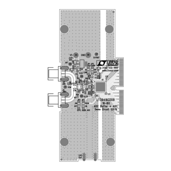
DESCRIPTION
Demonstration circuit 1257B features the LTC
2GHz low noise differential 16-Bit ADC buffer driving the
LTC2208, a 16-bit 130Msps ADC. The DC1257B is sup-
plied with a bandpass filter centered at 140MHz between
the buffer and the ADC. The filter center frequency can be
changed to optimize performance at different analog input
frequencies. Both single-ended and differential configura-
tions are supported at the inputs. The DC1257B has been
QUICK START PROCEDURE
Demonstration circuit 1257B is easy to set up. Refer to
Figure 1 for proper measurement equipment setup. Table 1
Table 1: DC1257B SMA Connector and Jumper Descriptions
+
J2 (A
)
IN
–
J3 (A
)
IN
J4 (CLK)
JP1 (PGA)
JP2 (RAND)
JP3 (SHDN ADC)
JP4 (DITH)
HARDWARE SETUP
The DC1257B requires DC890 FastDAACs data acquisition
board with PScope System Software. The PScope System
Software is available from the Linear Technology website
at http://www.linear.com/software/.
Apply power to the DC1257B Demonstration Circuit. Apply
+3.6V across the pins marked OPT and GND, VS and GND.
The DC1257B demonstration circuit requires up to 100mA
from the OPT pin, and up to 700 mA from the VS pin.
Arrow.com.
Downloaded from
Single-Ended/Differential Input. By default, this is configured as a single-ended input. Use this connector to supply an input to
the DC1257B. When driven from a 50Ω signal source, no external termination necessary.
Differential Input. Not connected by default. Capacitor C23 can be installed and C25 removed to drive the DC1257B differentially.
Single-Ended Input. This input is designed to be driven by an extremely low jitter 50Ω source. A sinusoidal input of up to 13dBm
is recommended.
Programmable gain amplifier. Default to LOW Gain Mode. This sets the gain of the ADC amplifier to 1.0.
ADC Digital Output Randomization. Default to OFF. This disables randomization.
ADC Power Shutdown ADC. Default to EN. This results in normal operation.
ADC Internal Dither Enable. Default to OFF. This disables internal dither.
DEMO MANUAL DC1257B
2 GHz Low Noise Differential
®
6416, a
developed from the DC996B-B, used to characterize the
LTC2208 family of ADCs.
Use the DC1257B with a DC890 FastDAACS and PScope™
software to collect time and frequency data.
Design files for this circuit board are available at
http://www.linear.com/demo
L, LT, LTC, LTM, Linear Technology and the Linear logo are registered trademarks of Linear
Technology Corporation and PScope is a trademark of Linear Technology Corporation. All other
trademarks are the property of their respective owners.
describes the function of each SMA connector and default
settings for the jumpers on the board.
Supply power to the DC890B FastDAACS Board with an
external 6V ±0.5V 1A supply on turrets on G7(+) and G1(–)
or the adjacent 2.1mm power jack. Unless the DC890B
detects external power it will not activate the LVDS mode of
the Xilinx Spartan-III FPGA. The FPGA actively terminates
the LVDS repeaters at the outputs of the LTC2208.
LTC6416
16-Bit ADC Buffer
dc1257bf
1
Advertisement
Table of Contents

Subscribe to Our Youtube Channel
Related Manuals for Linear Technology DC1257B


Summary of Contents for Linear Technology DC1257B
- Page 1 – J3 (A Differential Input. Not connected by default. Capacitor C23 can be installed and C25 removed to drive the DC1257B differentially. J4 (CLK) Single-Ended Input. This input is designed to be driven by an extremely low jitter 50Ω source. A sinusoidal input of up to 13dBm is recommended.
-
Page 2: Hardware Setup
DEMO MANUAL DC1257B HARDWARE SETUP Apply Encode Clock to the DC1257B on the SMA connector Collect Data by clicking on the “Collect” button. Time and marked “(J4) CLK". This transformer coupled input is frequency plots will be displayed in the PScope window. - Page 3 – – – – 100Ω 25Ω 1.5pF CLLO 6416 F05 0.01μF CLOCK (130MHz) Figure 2. DC1257B Simplified Schematic with Recommended Output Termination for Driving an LTC2208 16-Bit ADC at 140MHz dc1257bf Arrow.com. Arrow.com. Arrow.com. Downloaded from Downloaded from Downloaded from...
-
Page 4: Parts List
DEMO MANUAL DC1257B PARTS LIST ITEM REFERENCE PART DESCRIPTION MANUFACTURER/PART NUMBER C8-C12, C19, C25, C26, C28-C31 CAP., X7R, 0.1μF, 25V, 20% 0603 AVX, 06033C104MAT2A C13, C14, C18, C27 CAP., X5R, 0.1μF, 16V, 10% 0402 AVX, 0402YD104KAT2A CAP., X5R, 2.2μF, 6.3V, 10% 0603 AVX, 06036D225KAT2A CAP., C0G, 220pF, 16V, 10% 0402... -
Page 5: Schematic Diagram
Information furnished by Linear Technology Corporation is believed to be accurate and reliable. However, no responsibility is assumed for its use. Linear Technology Corporation makes no representa- tion that the interconnection of its circuits as described herein will not infringe on existing patent rights. - Page 6 Linear Technology Corporation (LTC) provides the enclosed product(s) under the following AS IS conditions: This demonstration board (DEMO BOARD) kit being sold or provided by Linear Technology is intended for use for ENGINEERING DEVELOPMENT OR EVALUATION PURPOSES ONLY and is not provided by LTC for commercial use. As such, the DEMO BOARD herein may not be complete in terms of required design-, marketing-, and/or manufacturing-related protective considerations, including but not limited to product safety measures typically found in finished commercial goods.
Need help?
Do you have a question about the DC1257B and is the answer not in the manual?
Questions and answers