Table of Contents
Advertisement
Quick Links
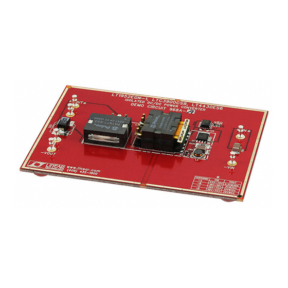
QUICK START GUIDE FOR DEMONSTRATION CIRCUIT 968A-B
DESCRIPTION
Demonstration circuit 968A-B is isolated input to high
current output 1/8th Brick footprint converter featur-
ing the LT ® 1952 switching controller. The DC968
converts isolated 18V to 36V input to 5V output and
provides over 20A of output current. The converter
operates at 300kHz with efficiency greater than 93%.
The DC968 can be easily modified to generate output
voltages in the range from 0.6V to 28V. The output
currents are limited by total output power of up to
200W. The other available versions of DC968A are:
DC968A-A 36-75Vin to 3.3V@30A
DC968A-C 36-75Vin to 12V@12A
DC968A-D 36-75Vin to 28V@4A
Also, the DC968 can be modified for other input volt-
ages like 8V-36V, 18V-75V, 44V-52V, and so on. The
wider input voltage range will decrease the converter
Performance Summary
Table 1.
PARAMETER
Minimum Input Voltage
Maximum Input Voltage
V OUT
Typical Output Ripple V OUT
Nominal Switching Frequency
QUICK START PROCEDURE
Demonstration circuit 968 is easy to set up to evalu-
ate the performance of LT1952 circuit. Refer to Fig-
ure 1 for proper measurement equipment setup and
follow the procedure below:
NOTE: When measuring the input or output voltage
ripple, care must be taken to avoid a long ground lead
on the oscilloscope probe. Measure the input or out-
put voltage ripple by touching the probe tip directly
ISOLATED DC/DC POWER CONVERTER
efficiency. Therefore, narrow input voltage range will
be more desirable.
The DC968 circuit features soft-start which prevents
output voltage overshoot on startup or when recover-
ing from overload condition.
The DC968 has precise over-current protection circuit
that allows for continuous operation under short cir-
cuit conditions. The low power dissipation under
short circuit conditions insures high reliability even
during short circuits.
The LT1952 can be synchronized to an external clock
of up to 400kHz. Please refer to LT1952 data sheet for
design details and applications information.
Design files for this circuit board are available. Call
the LTC factory.
LT is a trademark of Linear Technology Corporation
CONDITION
I OUT = 0A to 20A
I OUT = 0A to 20A
V IN = 18V to 36V, I OUT = 0A to 20A
V IN = 18V to 36V, I OUT = 0A to 20A
across the Vin or Vout and GND terminals. See Figure
2. for proper scope probe technique.
With power off, connect the input power supply to
1.
Vin and GND. Make sure that the input power sup-
ply has sufficient current rating at minimum input
voltage for the required output load.
Turn on the power at the input.
2.
LT1952
VALUE
18V
36V
5V ±3%
50mV P–P
300kHz
1
Advertisement
Table of Contents

Related Manuals for Linear Technology 968A-B


Summary of Contents for Linear Technology 968A-B
- Page 1 QUICK START GUIDE FOR DEMONSTRATION CIRCUIT 968A-B ISOLATED DC/DC POWER CONVERTER LT1952 DESCRIPTION Demonstration circuit 968A-B is isolated input to high efficiency. Therefore, narrow input voltage range will current output 1/8th Brick footprint converter featur- be more desirable. ing the LT ® 1952 switching controller. The DC968...
- Page 2 QUICK START GUIDE FOR DEMONSTRATION CIRCUIT 968A-B ISOLATED DC/DC POWER CONVERTER NOTE: Make sure that the input voltage does not serve the output voltage regulation, ripple voltage, exceed 40V. efficiency and other parameters. Check for the proper output voltage. The DC968 is equipped with an output capacitor Vout = 5V.
- Page 3 QUICK START GUIDE FOR DEMONSTRATION CIRCUIT 968A-B ISOLATED DC/DC POWER CONVERTER Figure 2. Scope Probe Placement for Measuring Input or Output Ripple CHANGING THE OUTPUT VOLTAGE LT1952 DC968A-B 24V in to 5V out To set the output voltage lower than 5V, change the...
- Page 4 QUICK START GUIDE FOR DEMONSTRATION CIRCUIT 968A-B ISOLATED DC/DC POWER CONVERTER DEBUGGING AND TESTING The DC968 can easily be tested and debugged by powering the bias circuit separately from the main power circuit. To place DC968 into debug mode re- move the resistor R1 and connect 48V, 100mA power source to +Vb node (right side of R1).
- Page 5 QUICK START GUIDE FOR DEMONSTRATION CIRCUIT 968A-B ISOLATED DC/DC POWER CONVERTER BAS516 +Vin 1.5mH CDEP147NP-1R5MC-95 +Vo1 PZTA42 +Vin +Vout 2.2R Input Cin1 BAS516 HAT2165 HAT2165 +Vr2 Cin2 Csys 6.8uF, 50V PDZ9.1B 470uF, 6.3V -Vin 2, 3 +Vin HAT2244 4, 5 Boost 1.5n, 200V...
- Page 6 QUICK START GUIDE FOR DEMONSTRATION CIRCUIT 968A-B ISOLATED DC/DC POWER CONVERTER...
- Page 7 Mouser Electronics Authorized Distributor Click to View Pricing, Inventory, Delivery & Lifecycle Information: Analog Devices Inc. DC968A-B...
Need help?
Do you have a question about the 968A-B and is the answer not in the manual?
Questions and answers